
Presto 3 - Vacuum Cleaner Kärcher - Free user manual and instructions
Find the device manual for free Presto 3 Kärcher in PDF.

| Product type | Vacuum cleaner |
| Brand | Kärcher |
| Model | Presto 3 |
| Usage | Commercial (hotels, schools, offices, etc.) |
| Power supply | Mains electric |
| Nominal voltage | 230 V |
| Maximum power | 1500 W |
| Tank capacity | 15 L |
| Filtration type | Cartridge filter |
| Power cord length | 10 m |
| Noise level | 70 dB(A) |
| Tank material | Stainless steel |
| Included accessories | Floor nozzle, crevice tool, dusting brush |
| Safety | Float shut-off against overflow |
| Maintenance | Regular cleaning of filter and emptying of tank |
| Repairability | Spare parts available from the manufacturer |
| Grounding | Mandatory for safe operation |
| Operating conditions | Indoors only |
| Compatible chemicals | Alkalis, aldehydes, detergents, soaps (avoid chlorinated hydrocarbons) |
| Weight | 12 kg |
| Dimensions (L x W x H) | 50 x 40 x 60 cm |
Frequently Asked Questions - Presto 3 Kärcher
User questions about Presto 3 Kärcher
0 question about this device. Answer the ones you know or ask your own.
Ask a new question about this device
Download the instructions for your Vacuum Cleaner in PDF format for free! Find your manual Presto 3 - Kärcher and take your electronic device back in hand. On this page are published all the documents necessary for the use of your device. Presto 3 by Kärcher.
USER MANUAL Presto 3 Kärcher
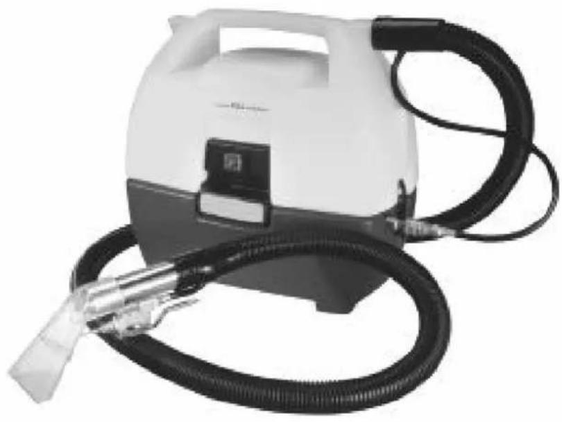
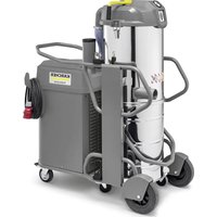
Spotter / Mini Extractor
Operating instructions (ENG)
Model: 1.003-012.0
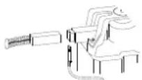
natural_image
White and black industrial spray gun with coiled hose and connector (no visible text or symbols)From Serial Number (Ref No1*)
*See Serial Number page
in Spare Parts List
or call manufacturer
Model:
Date of Purchase: ____
Serial Number: ____
Dealer:
Address:
Phone Number:
Sales Representative: ____
Warranty Registration
Thank you for purchasing a Kärcher North America product. Warranty registration is quick and easy. Your registration will allow us to serve you better over the lifetime of the produc
To register your product go to :
http://warranty.karcherna.com/
For customer assistance:
1-800-444-7654
Machine Data Label 2
Table of Contents 3
How To Use This Manual 4
Safety
IMPORTANT SAFETY INSTRUCTIONS ..... 5
CONSIGNES DE SÉCURITÉ IMPORTANTES .. 6
HAZARD INTENSITY LEVEL 7
NIVEAU D'INTENSITÉ DU DANGER. . . . . . . . . 8
Grounding Instructions 9
Operations
Set-up and Operation 10
Maintenance
Daily Maintenance 12
Periodic Maintenance 12
Shut Down and Storage 12
Solution Pump Replacement 12
Vacuum Motor Replacement 13
Troubleshooting 14
Suggested Spare Parts. 15
This manual contains the following sections:
• How to Use This Manual
- Safety
- Operations
- Maintenance
• Suggested Spare Parts
The HOW TO USE THIS MANUAL section will tell you how to find important information for ordering correct repair parts.
Parts may be ordered from authorized dealers. When placing an order for parts, the machine model and machine serial number are important. Refer to the MACHINE DATA box which is filled out during the installation of your machine. The MACHINE DATA box is located on the inside of the front cover of this manual.

The model and serial number of your machine is located on the back of the machine.
The SAFETY section contains important information regarding hazardous or unsafe practices of the machine. Levels of hazards are identified that could result in product damage, personal injury, or severe injury resulting in death.
The OPERATIONS section is to familiarize the operator with the operation and function of the machine.
The MAINTENANCE section contains preventive maintenance to keep the machine and its components in good working condition. They are listed in this general order:
- Storage
- Maintenance
- Troubleshooting
NOTE: If a service or option kit is installed on your machine, be sure to keep the KIT INSTRUCTIONS which came with the kit. It contains replacement parts numbers needed for ordering future parts.
NOTE: The manual part number is located on the lower right corner of the front cover.
IMPORTANT SAFETY INSTRUCTIONS
When using this machine, basic precaution must always be followed, including the following: READ ALL INSTRUCTIONS BEFORE USING THIS MACHINE.
WARNING:
To reduce the risk of fire, electric shock, or injury:
Use only indoors. Do not use outdoors or expose to rain.
Use only as described in this manual. Use only manufacturer's recommended components and attachments.
If the machine is not working properly, has been dropped, damaged, left outdoors, or dropped into water, return it to an authorized service center.
Do not operate the machine with any openings blocked. Keep openings free of debris that may reduce airflow.
This machine is not suitable for picking up hazardous dust.
Do not operate this machine near flammable fluids, dust or vapors.
During operation, attention shall be paid to other persons, especially children.
When leaving unattended, secure against unintentional movement.
The machine shall only be operated by instructed and authorized persons.
When leaving unattended, switch off or lock the main power switch to prevent unauthorized use.
Do not handle the plug or machine with wet hands.
Do not unplug machine by pulling on cord. To unplug, grasp the plug, not the cord.
Do not use with damaged cord or plug. Follow all instructions in this manual concerning grounding the machine.
Do not pull or carry by cord, use cord as a handle, close a door on cord, or pull cord around sharp edges or corners.
Do not pull/run machine over cord. Keep cord away from heated surfaces.
Connect to a properly grounded outlet. See Grounding Instructions.
READ AND SAVE THESE INSTRUCTIONS
CONSIGNES DE SÉCURITÉ IMPORTANTES
The following symbols are used throughout this guide as indicated in their descriptions:
HAZARD INTENSITY LEVEL
There are three levels of hazard intensity identified by signal words -WARNING and CAUTION and FOR SAFETY. The level of hazard intensity is determined by the following definitions:
WARNING:
WARNING - Hazards or unsafe practices which COULD result in severe personal injury or death.
CAUTION:
CAUTION - Hazards or unsafe practices which could result in minor personal injury or product or property damage.
FOR SAFETY: To Identify actions which must be followed for safe operation of equipment.
Report machine damage or faulty operation immediately. Do not use the machine if it is not in proper operating condition. Following is information that signals some potentially dangerous conditions to the operator or the equipment. Read this information carefully. Know when these conditions can exist. Locate all safety devices on the machine. Please take the necessary steps to train the machine operating personnel.
FOR SAFETY:
DO NOT OPERATE MACHINE:
Unless Trained and Authorized.
Unless Operation Guide is Read and understood.
In Flammable or Explosive areas.
In areas with possible falling objects
WHEN SERVICING MACHINE:
Avoid moving parts. Do not wear loose clothing; jackets, shirts, or sleeves when working on the machine. Use manufacturer approved replacement parts.
NOTE: These drawings indicate the location of safety labels on the machine. If at any time the labels become illegible, promptly replace them.
WARNING LABEL 86220140
Grounding Instructions
THIS PRODUCT IS FOR COMMERCIAL USE ONLY.
Electrical:
In the USA this machine operates on a standard 15 amp 115V, 60 Hz, A.C. power circuit. The amp, hertz, and voltage are listed on the data label found on each machine. Using voltages above or below those indicated on the data label will cause serious damage to the motors.
Extension Cords:
If an extension cord is used, the wire size must be at least one size larger than the power cord on the machine, and must be limited to 50 feet (15.5m) in length.
Grounding Instructions:
This appliance must be grounded. If it should malfunction or break down, grounding provides a path of least resistance for electric current to reduce the risk of electric shock. This appliance is equipped with a cord having an equipment-grounding conductor and grounding plug. The plug must be inserted into an appropriate outlet that is properly installed and grounded in accordance with all local codes and ordinances.
This appliance is for use on a nominal 120-volt circuit, and has a grounded plug that looks like the plug in "Fig. A". A temporary adaptor that looks like the adaptor in "Fig. C" may be used to connect this plug to a 2-pole receptacle as shown in "Fig. B", if a properly grounded outlet is not available. The temporary adaptor should be used only until a properly grounded outlet (Fig. A) can be installed by a qualified electrician. The green colored rigid ear, lug, or wire extending from the adaptor must be connected to a permanent ground such as a properly grounded outlet box cover. Whenever the adaptor is used, it must be held in place by a metal screw.

WARNING:
Improper connection of the equipment-grounding conductor can result in a risk of electric shock. Check with a qualified electrician or service person if you are in doubt as to whether the outlet is properly grounded. Do not modify the plug provided with the appliance - if it will not fit the outlet, have a proper outlet installed by a qualified electrician.
AVERTISSEMENT:
Set-up and Operation
- Upon removing your new mini-extractor from the box, loosen the latch at back end of the machine that secures the recovery tank to the solution tank. Remove the recovery tank from the solution tank.
- Pour clean, hot water to the indicated fill line of the solution tank. To avoid possible tank distortion, water temperature must not exceed 140 F (60C).
- Add a non-foaming cleaning solution concentrate, for use in hot water extractors at the proportions noted on the container (See list below), into solution tank.
- Place the recovery tank back onto the solution tank and refasten the latch.
- Plug the power cord into grounded outlet (See GROUNDING INSTRUCTIONS).
- Connect the vacuum and cleaning tool hoses to the extractor. This unit is equipped with an 1/8" male quick connect for solution hose attachment and a 1" ID vacuum hose hookup. Insure that the female solution hose coupler is securely locked onto the male coupler on the extractor.
- Turn switch ON. This switch operates both the vacuum motor and the water pump. NOTE: The pump is an oscillating pump and should not be run dry for extended periods of time. This may cause damage to your pump, therefore voiding your warranty.
- Squeeze the solution lever on the cleaning tool to spray cleaning solution and place the vacuum head on the surface to be cleaned. Normally, chemical is applied on the push stroke while vacuuming is done on the pull stroke. For heavily soiled carpets the hand tool may be used in the scrubbing manner, applying chemical in both the push and pull stroke. Always finish up an area with a vacuum pull stroke.
- When cleaning, be sure to monitor the level of recovered solution in the recovery tank. When the solution reaches the FULL mark, shut off the extractor, loosen the latches and empty the recovery tank.
NOTE: Dispose of waste in a proper manner which would not violate any Local, State or Federal law.
CAUTION:
Operating vacuum with solution above the FULL mark could draw water directly into the vac motor. This will cause damage to the motor, therefore voiding your warranty.
ATTENTION:
Always Test Upholstery/carpet For Color Fastness In An Inconspicuous Place. Also, To Avoid Prolonged Drying Times, Do Not Spray Too Much Solution In Any One Area.
ATTENTION:
Always use defoamer if foaming occurs. Foam will suspend large particles which may damage vacuum as well as allow liquid into the vacuum motor without activating the float shutoff.
ATTENTION:
To prevent possible disease hazard, before attempting to clean bodily fluids spills, you must kill any viruses, germs or bacteria present in the bodily fluid.
ATTENTION:
*Registered Trademark
Daily Maintenance
Follow same procedure for Shut Down and Storage.
Periodic Maintenance
- Twice a month, flush a white vinegar solution (one quart vinegar to two gallons water) or anti-browning solution (mixed as directed) through the extractor. This will prevent build-up of alkaline residue in the system.
- If spray jet becomes clogged, remove the spray tip, wash it thoroughly, and blow dry.
NOTE: Do Not Use Pins, Wire, Etc. To Clean Nozzle As This Could Destroy The Spray Pattern.
- Apply silicone lubricant to solution nipple.
- Periodically inspect all hoses, electrical cable and connections on your machine. Frayed or cracked hoses should be repaired or replaced to eliminate vacuum or solution pressure loss. If the cable insulation on the power cord is broken or frayed, repair or replace immediately. Don't take chances with electrical fire or shock.
WARNING:
Before making any adjustments or performing any maintenance to your machine, disconnect the power cord from the electrical source.
▲ AVERTISSEMENT:
Shut Down and Storage
- Turn Switch OFF. Empty recovery tank completely and rinse several times to remove any dirt or debris that may be left behind.
- Tip the solution tank over a sink to drain any unused cleaning solution and rinse with clean water to remove any suds left behind by the cleaning chemicals.
NOTE: Dispose of waste in a proper manner which would not violate any Local, State or Federal law
- Run a small amount of clean water through pump if chemicals were used. This will help insure the life of your pump.
- Check the spray jet on the cleaning tool for full spray pattern and inspect vac head for any obstructions. Also make sure to clean the filter cap attached to portal cover of any debris that may have been trapped during cleaning.
- Remove as much moisture from system before storing in cold climates. Excess water may freeze during storage and crack internal components, causing damage to the unit.
WARNING:
Only qualified maintenance personnel are to perform repairs.
AVERTISSEMENT:
- Turn off all switches and unplug the machine.
- Unlatch and remove recovery tank.
- Unfasten screws holding vacuum motor housing to solution tank.
- Unfasten screws holding pump plate to bottom of solution tank.
- Remove solution hoses from fittings on pump.
- Remove pump from brackets and remove fittings and grounding wire.
- Reverse process to install new replacement pump.
Vacuum Motor Replacement
- Turn off all switches and unplug machine.
- Unlatch and remove recovery tank.
- Unfasten screws holding vacuum motor retainer to vacuum motor housing
- Lift vacuum motor from vacuum motor housing. Locate the vacuum motor wires and disconnect at the connector.
- Remove vacuum motor.
- Reverse process to install vacuum motor replacement.
WARNING: The green ground wire must be attached for safe operation. See wiring diagram.
If armature commutator is grooved, extremely pitted or not concentric, the motor will need to be replaced or sent to a qualified service center.
Important:
These brushes wear quicker as the length shortens due to increased heat. Spring inside brush housing will damage motor if brushes are allowed to wear away completely.
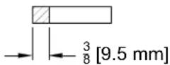
Periodically check the length of the carbon brushes. Replace both carbon brushes when either is less than 3/8" (9.5mm) long.
Troubleshooting
| PROBLEM CAUSE SOLUTION | ||
| Little or no solution flow C | Clogged spray jet on cleaning tool Remove and clean jets | |
| Faulty pump Check and replace pump | ||
| Incorrectly attached solution hose Ensure solution hose coupler is securely attached to the coupler on the solution tank | ||
| Loss of vacuum/Solution recovery | Incorrectly attached vacuum hose Ensure Vacuum hose is pushed completely onto the recovery tank inlet. | |
| Obstruction in cleaning tool Inspect for and remove any debris. | ||
| Recovery tank is not securely mounted on the solution tank | Tighten latch on either end of the machine | |
| REF | PART NO. | DESCRIPTION | SERIAL NO.FROM | NOTES: |
| 1 | 86 | 225110 SWITCH, DPST 250V 16(4) SPLASH | ||
| 2 | 86 | 258440 VAC MOTOR, 120V 2ST LNP | ||
| 3 | 86 | 201110 PUMP, 110/120 60HZ FLOJET | ||
| 4 | 86 | 135320 BRUSH SET, 120V VAC 120V MOTOR ONLY |
Table of contents
| SPOTTER, 120V US (1.003-012.0) | 2 | |
| 9030 EXTRACTOR | 3 | |
| 9040 SOLUTION PUMP | 6 | |
| 9050 WIRING DIAGRAM | 8 | |
| 9060 HAND TOOL | 10 | |
| 9070 MINI CART | 12 | |
| 9080 CART | 14 | |
SPOTTER, 120V US (1.003-012.0)
POS Description Quantity Unit
9030 EXTRACTOR 1.000 ST
9040 SOLUTION PUMP 1.000 ST
9050 WIRING DIAGRAM 1.000 ST
9060 HAND TOOL 1.000 ST
9070 MINI CART 1.000 ST
9080 CART 1.000 ST
Valid on 26.09.2018 Page 3 / 15
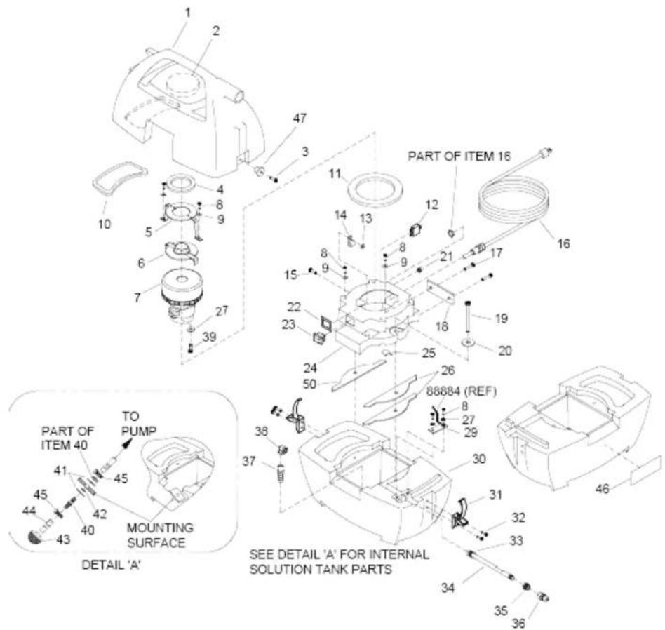
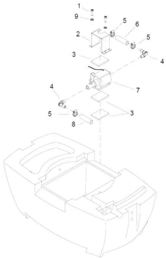
9030 EXTRACTOR
POS Article no. Description Quantity Unit Remark
1 8.622-520.0 Tank RECOVERY PRESTO 1.000 ST
2 8.623-652.0 FOAM, 4.00 O.D. X 1.00 THK 1.000 ST
3 8.622-373.0 Screw 8-32 X 1/2 FHMS STL BLK ZNPLT 2.000 ST
4 8.623-744.0 Seal 4.06 x 2.50 x .38 1.000 ST
5 8.622-344.0 Retainer vac motor 1.000 ST
6 8.621-731.0 Cover vac motor 1.000 ST
7 8.625-844.0 Vac motor 120V 5.7 2ST LNP 1.000 ST
8 8.627-429.0 SCREW, 10-32 X .375 PHPNHMS SS 6.000 ST
9 8.622-577.0 Washer M6 FLT SS 4.000 ST
10 8.623-741.0 GASKET, SPOTTER RECOVERY 1.000 ST
11 8.623-742.0 GASKET, 4.0"X5.5-X.25T PORON 1.000 ST
12 8.621-567.0 BREAKER, 8A VDE CIRCUIT 1.000 ST
13 8.601-069.0 WASHER, 1/8 RIVET 1.000 ST
14 8.626-116.0 Capacitor assembly EMI SPOTTER 1.000 ST
15 8.613-654.0 RIVET, M4 X 18GL 1.000 ST
16 8.621-706.0 Cord assembly 14X3 25' YLW SPOTTER 1.000 ST U.S. MACHINE
17 8.613-655.0 RIVET, M3 X 12GL 2.000 ST
18 8.607-965.0 Plate Data Label 1.000 ST
19 8.627-587.0 SCREW, 1/4-20 X 1.5 PHPNHMS SS 2.000 ST
20 8.622-576.0 Washer M8 FLT STL ZNPLT 2.000 ST
21 8.600-201.0 BOOT, 3/8 CIRCUIT BREAKER 1.000 ST
22 8.623-351.0 Clip Switch Retaining 1.000 ST
23 8.622-511.0 Switch DPST 250V 16(4) SPLASH 1.000 ST
24 8.621-931.0 Housing vacuum PRESTO 1.000 ST
25 8.623-746.0 GASKET, .31 X .75 X 1.98 1.000 ST
26 8.623-745.0 GASKET, VAC HOUSING 3/16" 2.000 ST
27 8.601-064.0 Washer #10 LOCK EXT STAR 55 3.000 ST
28 8.621-803.0 GASKET, VAC HOUSING 3/8" 1.000 ST
29 8.606-856.0 Bracket nipple PRESTO 1.000 ST
30 8.622-519.0 Tank SOLUTION, TRIM 1.000 ST
31 8.624-618.0 LATCH, PRESTO TANK 2.000 ST
32 8.600-652.0 SCREW, 8-32 X .375 PHPNHMS SS 4.000 ST
33 8.621-816.0 GASKET, GROUND WIRE 1.000 ST
Valid on 26.09.2018 Page 4 / 15
9030 EXTRACTOR
POS Article no. Description Quantity Unit Remark
34 8.624-774.0 Nipple 1/4 X 6.0 BRASS 1.000 ST
35 8.622-722.0 Adapter 1/8MPT X 1/4FPT Brass 1.000 ST
36 8.620-082.0 Nipple 1/8 1.000 ST
37 8.619-758.0 Hosebarb 1/4MPT X 3/8 1.000 ST
38 8.619-737.0 ELBOW, 1/4FPT X 1/4FPT 1.000 ST
39 8.628-845.0 SCREW, M4.8 X 10 PHTF TYPEB 1.000 ST
40 8.625-831.0 Bulkhead union 1.000 ST
41 8.627-932.0 WASHER, .515 X .875 X .063 FLT SS 2.000 ST
42 8.624-809.0 O-ring seal .500 ID X.688 OD X.103 1.000 ST
43 8.600-770.0 Strainer 80 MESH X 3/8 FPT 1.000 ST
44 8.621-901.0 Hose 3/8ID SGLBRD RBR X 5" 1.000 ST
45 8.623-315.0 CLAMP, 3/8 HOSE (D-SLOT) 2.000 ST
46 8.622-014.0 LABEL, WARNING 1.000 ST
47 8.624-179.0 KEEPER, PRESTO LATCH 2.000 ST
9040 SOLUTION PUMP
Valid on 26.09.2018 Page 6 / 15
9040 SOLUTION PUMP
POS Article no. Description Quantity Unit
1 8.627-571.0 Screw 10-32 X .375 PHPNH 2.000 ST
2 8.606-869.0 Bracket solenoid pump PRESTO 1.000 ST
3 8.623-753.0 GASKET, TUBE SEAL 3.000 ST
4 8.619-759.0 Hosebarb 1/8MPT x 3/8 90D 2.000 ST
5 8.623-315.0 CLAMP, 3/8 HOSE (D-SLOT) 3.000 ST
6 8.624-029.0 Hose 3/8ID WIREBOUND X 2.6" 1.000 ST
7 8.620-111.0 PUMP, 110/120 60HZ FLOJET 1.000 ST
8 8.628-131.0 Hose 3/8ID WIREBOUND X 8.8" 1.000 ST
9 8.601-064.0 Washer #10 LOCK EXT STAR SS 2.000 ST
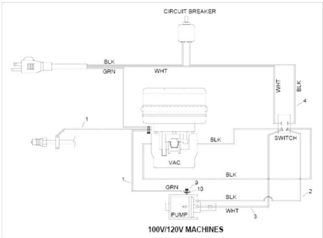
9050 WIRING DIAGRAM
flowchart
graph TD
    A["Power Source"] --> B["BLK"]
    B --> C["GRN"]
    C --> D["WHT"]
    D --> E["Switch"]
    E --> F["BLK"]
    F --> G["VAC"]
    G --> H["BRIP"]
    H --> I["PUMP"]
    I --> J["BLK"]
    J --> K["WHT"]
    K --> L["BRIP"]
    L --> M["SWITCH"]
    M --> N["BLK"]
    N --> O["WHT"]
    O --> P["BRIP"]
    P --> Q["SWITCH"]
    Q --> R["BLK"]
    R --> S["WHT"]
    S --> T["BRIP"]
    T --> U["SWITCH"]
    U --> V["BLK"]
    V --> W["WHT"]
    W --> X["BRIP"]
    X --> Y["SWITCH"]
    Y --> Z["BLK"]
    Z --> AA["WHT"]
    AA --> AB["BRIP"]
    AB --> AC["SWITCH"]
    AC --> AD["BLK"]
    AD --> AE["WHT"]
    AE --> AF["BRIP"]
    AF --> AG["SWITCH"]
Valid on 26.09.2018 Page 8 / 15
9050 WIRING DIAGRAM
POS Article no. Description Quantity Unit
1 8.622-631.0 Wire 18.5" GRN/18 76008 X 76008 2.000 ST
2 8.622-610.0 Wire 15" BLK/14 76050 X 76029 1.000 ST
3 8.622-611.0 Wire 15.4" WHT/14 76050 X 76029 1.000 ST
4 8.622-612.0 Wire 9" BLK/14 76029 X 76029 1.000 ST
5 8.600-677.0 SCREW, 10-32 X .25 PHPNHTF STL ZNPLT 1.000 ST
6 8.601-064.0 Washer #10 LOCK EXT STAR SS 1.000 ST
9060 HAND TOOL
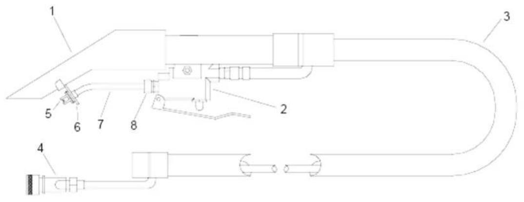
9060 HAND TOOL
| POS Article no. | Description Quantity Unit Remark |
| - 8.621-879.0 | HANDTOOL, SPOTTER 1.000 ST ENTIRE ASSEMBLY AS KIT |
| 1 | 8.621-934.0 Housing handtool SPOTTER 1.000 ST |
| 2 | 8.622-567.0 Valve complete SPOTTER 1.000 ST |
| 3 | 8.621-902.0 Hose assembly VAC/SOLUTION 1.000 ST |
| 4 | 8.620-081.0 Nipple 1/8 FPT QD FEM BRASS 1.000 ST |
| 5 | 8.621-957.0 JET assembly W/O-RING OKA 1.000 ST |
| 6 | 8.622-310.0 Plate retainer W/HARDWARE 1.000 ST |
| 7 | 8.622-191.0 Manifold SPOTTER 1.000 ST |
| 8 | 8.621-800.0 Fitting 1/8 MPT X 3/16 COMP 1.000 ST |
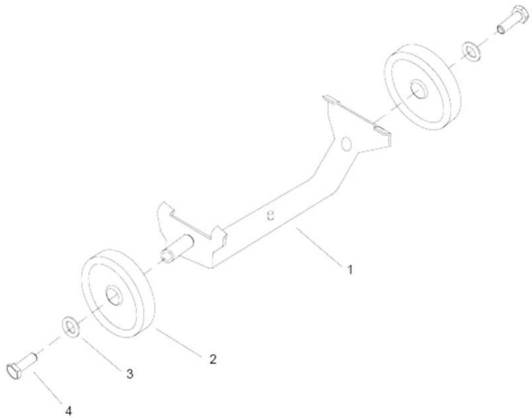
9070 MINI CART
Valid on 26.09.2018 Page 12 / 15
9070 MINI CART
POS Article no. Description Quantity Unit
-8.622-203.0 MINI-CART 1.000 ST
1 8.622-295.0 Plate weldment 1.000 ST
2 8.625-977.0 WHEEL, 5"D X 1\~X .5\~ID GRY 2.000 ST
3 8.613-728.0 WASHER, M8 FLT STL DIN125A ZNPLT 2.000 ST
4 8.613-664.0 SCREW, M8-1.25 X 20 HHMS ZNPLT 2.000 ST
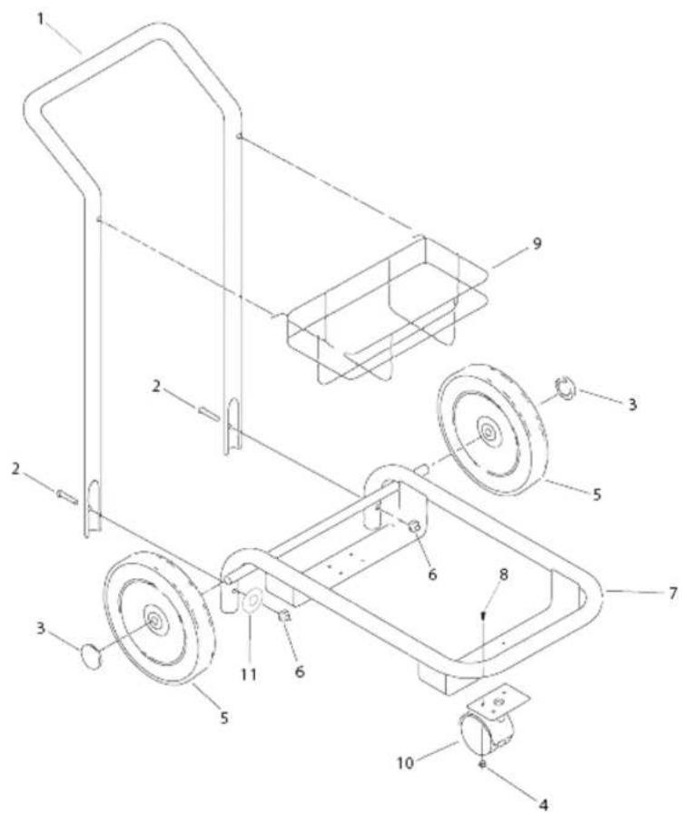
9080 CART
Valid on 26.09.2018 Page 14 / 15
9080 CART
| POS Article no. | Description Quantity Unit Remark | |
| - 8.600-003.0 | SPOTTER CART U19808 1.000 ST ENTIRE ASM AS KIT | |
| 1 | 8.608-927.0 Tube handle cart 1.000 ST | |
| 2 | 8.627-374.0 SCREW, 1/4-20 X 1.5 HHCS SS 2.000 ST | |
| 3 | 8.627-138.0 NUT, 1/2 DOME PUSH STL ZNPLT 2.000 ST | |
| 4 | 8.600-570.0 NUT, 10-32 HEXSTRW LK STL ZNPLT 4.000 ST | |
| 5 | 8.625-997.0 X-REF TO 8.639-789.0 7/15 2.000 ST | |
| 6 | 8.600-568.0 NUT, 1/4-20 HEX NYLOCK STL GR2 ZNPLT | 2.000 ST |
| 7 | 8.609-213.0 CART BASE ASM, SPOTTER | 1.000 ST |
| 8 | 8.600-659.0 SCREW, 10-32 X .5 PHPNHMS SS NP | 2.000 ST |
| 9 | 8.622-834.0 Carrying basket 3 bottle | 1.000 ST |
| 10 | 8.623-253.0 CASTER, 2.5 DIA | 1.000 ST |
| 11 | 8.601-063.0 WASHER, 1/4 SS | 2.000 ST |


- Spotter / Mini Extractor
- Warranty Registration
- Safety
- Operations
- Maintenance
- IMPORTANT SAFETY INSTRUCTIONS
- WARNING:
- READ AND SAVE THESE INSTRUCTIONS
- CONSIGNES DE SÉCURITÉ IMPORTANTES
- HAZARD INTENSITY LEVEL
- CAUTION:
- FOR SAFETY: To Identify actions which must be followed for safe operation of equipment.
- FOR SAFETY:
- WHEN SERVICING MACHINE:
- Grounding Instructions
- THIS PRODUCT IS FOR COMMERCIAL USE ONLY.
- Electrical:
- Extension Cords:
- Grounding Instructions:
- AVERTISSEMENT:
- Set-up and Operation
- ATTENTION:
- Daily Maintenance
- Periodic Maintenance
- ▲ AVERTISSEMENT:
- Shut Down and Storage
- Vacuum Motor Replacement
- Important:
- EXTRACTOR
- SOLUTION PUMP
- WIRING DIAGRAM
- HAND TOOL
- MINI CART
Brand : Kärcher
Model : Presto 3
Category : Vacuum Cleaner