NK36N7000SS - Basket SAMSUNG - Free user manual and instructions
Find the device manual for free NK36N7000SS SAMSUNG in PDF.

| Product Type | Kitchen range hood |
| Brand | Samsung |
| Model | NK36N7000SS |
| Width | 36 in (91.4 cm) |
| Recommended mounting height | 24 in (61 cm) min. for electric cooking, 27 in (68.5 cm) min. for gas, 36 in (91.4 cm) max. suggested |
| Power supply | 120 V AC, 60 Hz, 15 A |
| Maximum airflow (Power mode) | 600 CFM (Normal mode: 390 CFM) |
| Fan speeds | 4 speeds (Low, Med, High, Boost) |
| Lighting | Integrated LED lamps, dimmable |
| Connectivity | Bluetooth for pairing with Samsung cooktop; SmartThings app |
| Timer | Programmable delayed shut-off up to 99 minutes |
| Grease filter | Dishwasher-safe stainless steel baffle filter |
| Charcoal filter (optional) | Required for recirculation mode, replace every 4-6 months |
| Venting | Top outlet 6 in round (15.2 cm) or rear outlet 3 1/4 x 10 in (8.3 x 25.4 cm) |
| Ductless operation (recirculation) | Possible with recirculation kit NK-AF030FNB/AA and charcoal filter NK-AR050FNB/AA |
| Filter maintenance alarm | Yes, flashing after 50 hours of use |
| Sound level | Not specified, estimated 45-65 dB depending on speed |
| Approximate weight | 13.6 kg (30 lb) |
| Warranty | 1 year parts and labor |
| Surface care | Clean with soft cloth and mild detergent, do not use chlorine products |
Frequently Asked Questions - NK36N7000SS SAMSUNG
User questions about NK36N7000SS SAMSUNG
0 question about this device. Answer the ones you know or ask your own.
Ask a new question about this device
Download the instructions for your Basket in PDF format for free! Find your manual NK36N7000SS - SAMSUNG and take your electronic device back in hand. On this page are published all the documents necessary for the use of your device. NK36N7000SS by SAMSUNG.
USER MANUAL NK36N7000SS SAMSUNG
Important Safety Instructions 3
Installation Requirements 5
Electrical Requirements 5
Venting Requirements 5
Venting Methods 5
Tools and Parts 6
Dimensions and Clearances 6
Installation 7
Prepare Location 7
Installing the Range Hood 8
Connect Vent System 9
Electrical Connection 10
Complete Installation 11
Range Hood Use 11
Range Hood Description 11
Range Hood Controls 11
Connectivity Cooktop / Hood Range 12
Range Hood Care 13
Cleaning 13
Replacing a LED Lamp 13
Accesories 13
Warranty (USA) 14
Warranty (Canada) 15
APPROVED FOR RESIDENTIAL APPLIANCES
READ AND SAVE THESE INSTRUCTIONS
PLEASE READ ENTIRE INSTALLATION GUIDE BEFORE PROCEEDING. INSTALLATION MUST COMPLY WITH ALL LOCAL CODES.
IMPORTANT: Save these Instructions for the Local Electrical Inspector's use.
INSTALLER: Please leave these Instructions with this unit for the owner.
OWNER: Please retain these instructions for future reference.
Symbols used in this manual

WARNING
Hazards or unsafe practices that may result in severe personal injury or death.

CAUTION
Hazards or unsafe practices that may result in electric shock, personal injury, or property damage.

NOTE
Useful tips and instructions
These warning icons and symbols are here to prevent injury to you and others.
Please follow them explicitly. After reading this section, keep it in a safe place for future reference.

WARNING
Turn off power circuit at service panel and lock out panel before wiring this appliance.
Requirement 120 VAC, 60 Hz. 15 or 20 A Branch Circuit
State of California Proposition 65 warning (US only)

WARNING
This product contains chemicals known to the State of California to cause cancer and birth defects or other reproductive harm.
1. FCC Notice

CAUTION
FCC CAUTION: Any changes or modifications not expressly approved by the party responsible for compliance could void the user's authority to operate the equipment.
This device complies with Part 15 of FCC Rules. Operation is Subject to following two conditions:
1) This device may not cause harmful interference, and 2) This device must accept any interference received including interference that cause undesired operation.
For products sold in the US and Canadian markets, only channels 1\~11 are available. You cannot select any other channels.
FCC STATEMENT:
This equipment has been tested and found to comply within the limits for a Class B digital device, pursuant to part 15 of the FCC Rules. These limits are designed to provide reasonable protection against harmful interference in a residential installation.
This equipment generates, uses, and can radiate radio frequency energy and, if not installed and used in accordance with the instructions, may cause harmful interference to radio communications.
However, there is no guarantee that interference will not occur in a particular installation. If this equipment does cause harmful interference to radio or television reception, which can be determined by turning the equipment off and on, the user is encouraged to try to correct the interference by one or more of the following measures:
- Reorienting or relocating the receiving antenna
- Increasing the separation between the equipment and receiver
- Connecting the equipment to an outlet that is on a different circuit than the radio or TV.
- Consulting the dealer or an experienced radio/TV technician for help.
FCC RADIATION EXPOSURE STATEMENT:
This equipment complies with FCC radiation exposure limits set forth for an uncontrolled environment. This equipment should be installed and operated so there is at least 8 inches (20 cm) between the radiator and your body. This device and its antenna(s) must not be co-located or operated in conjunction with any other antenna or transmitter.
2. IC Notice
The term "IC" before the radio certification number only signifies that Industry Canada technical specifications were met. Operation is subject to the following two conditions: (1) this device may not cause interference, and (2) this device must accept any interference, including interference that may cause undesired operation of the device.
This Class B digital apparatus complies with Canadian ICES-003. For products sold in the US and Canadian markets, only channels 1\~11 are available. You cannot select any other channels.
IC RADIATION EXPOSURE STATEMENT:
This equipment complies with IC RSS-102 radiation exposure limits set forth for an uncontrolled environment. This equipment should be installed and operated so there is at least 8 inches (20 cm) between the radiator and your body. This device and its antenna(s) must not be co-located or operated in conjunction with any other antenna or transmitter.
Important Safety Instructions

WARNING
TO REDUCE THE RISK OF FIRE, ELECTRIC SHOCK, OR INJURY TO PERSONS, OBSERVE THE FOLLOWING PRECAUTIONS:
■ Use this unit only in the manner intended by the manufacturer. If you have questions, contact the manufacturer.
■ Before servicing or cleaning the unit, switch the power off at the service panel and lock the service panel to prevent power from being switched on accidentally. If the service panel cannot be locked, securely fasten a prominent warning device, such as a tag to the service panel.
■ Installation work and electrical wiring must be done by qualified person(s) in accordance with all applicable codes and standards, including fire-rated construction.
- Sufficient air is needed for proper combustion and exhausting of gases through the flue (chimney) of fuel burning equipment to prevent backdrafting. Follow the heating equipment manufacturer's guideline and safety standards such as those published by the National Fire Protection Association (NFPA), the American Society for Heating, Refrigeration and Air Conditioning Engineers (ASHRAE), and the local code authorities.
■ When cutting or drilling into the wall or ceiling; do not damage electrical wiring and other hidden utilities.
■ Ducted fans must always be vented outdoors.

CAUTION
For general ventilating use only. Do not use to exhaust hazardous or explosive materials and vapors.

CAUTION
To reduce the risk of fire and to properly exhaust air, be sure to duct air outside - do not vent exhaust air into spaces within walls or ceilings, attics or into crawl spaces, or garages.

WARNING
TO REDUCE THE RISK OF FIRE, USE ONLY METAL DUCTWORK.

WARNING
TO REDUCE THE RISK OF A RANGE TOP GREASE FIRE:
■ Never leave surface units unattended at high settings. Boilovers cause smoking and greasy spillovers that may ignite. Heat oils slowly on low or medium settings.
■ Always turn the hood ON when cooking at high heat or when flambeing food (i.e. Crepes Suzette, Cherries Jubilee, Peppercorn Beef Flambé).
■ Clean ventilating fans frequently. Grease should not be allowed to accumulate on the fan or filter.
■ Use proper pan sizes. Always use cookware appropriate for the size of the surface element.

WARNING
TO REDUCE THE RISK OF INJURY TO PERSONS IN THE EVENT OF A RANGE TOP GREASE FIRE, OBSERVE THE FOLLOWING PRECAUTIONS: ^a
■ SMOTHER FLAMES with a close fitting lid, cookie sheet, or metal tray, then turn off the burner. BE CAREFUL TO PREVENT BURNS. If the flames do not go out immediately, EVACUATE AND CALL THE FIRE DEPARTMENT.
■ NEVER PICK UP A FLAMING PAN - you may get burned.
■ DO NOT USE WATER, including wet dishcloths or towels -
a violent steam explosion can result.
■ Use an extinguisher ONLY if:
- You know you have a class ABC extinguisher, and you already know how to operate it.
– The fire is small and contained in the area where it started.
– The fire department is being called.
- You can fight the fire with your back to an exit.
^a Based on “Kitchen Fire Safety Tips” published by NFPA.

WARNING
To reduce the risk of fire or electrical shock, do not use this fan with any solid-state speed control device.

WARNING
Do not let children near this appliance. Do not let children play with this appliance.
Keep all packaging materials out of children's reach. Properly dispose the packaging materials after this appliance is unpacked.
Read and save these instructions
Electrical Requirements
IMPORTANT
Observe all governing codes and ordinances.
It is the customer's responsibility:
To contact a qualified electrical installer.
To assure that the electrical installation is adequate and in conformance with National Electrical Code, ANSI/NFPA 70
— latest edition*, or CSA Standards C22.1-94, Canadian
Electrical Code, Part 1 and C22.2 No.0-M91 - latest edition** and all local codes and ordinances.
If codes permit and a separate ground wire is used, it is recommended that a qualified electrician determine that the ground path is adequate.
A copy of the above code standards can be obtained from:
National Fire Protection Association
1 Batterymarch Park
Quincy, MA 02169-7471
CSA International
8501 East Pleasant Valley Road
Cleveland, OH 44131-5575
■ A 120 volt, 60 Hz., AC only, 15-amp, fused electrical circuit is required.
■ If the house has aluminum wiring, follow the procedure below:
1. Connect a section of solid copper wire to the pigtail leads.
2. Connect the aluminum wiring to the added section of copper wire using special connectors and/or tools designed and UL listed for joining copper to aluminum.
- Follow the electrical connector manufacturer's recommended procedure. Aluminum/copper connection must conform with local codes and industry accepted wiring practices.
■ Wire sizes and connections must conform with the rating of the appliance as specified on the model/serial rating plate. The model serial plate is located behind the filter on the rear wall of the range hood.
■ Wire sizes must conform to the requirements of the National Electrical Code, ANSI/NFPA 70 (latest edition), or CSA Standards C22.1-94, Canadian Electrical Code, Part 1 and C22.2 No. 0-M91 (latest edition) and all local codes and ordinances.
Venting Requirements (ducted models only)
- Vent system must terminate outdoors.
- Do not terminate the vent system in an attic or other enclosed area.
- Do not use a 4" (10.2 cm) laundry-type wall cap.
- Use metal vent only. Rigid metal vent is recommended. Plastic or metal foil vent is not recommended.
- The length of the vent system and the number of elbows should be kept to a minimum to provide efficient performance.
For the most efficient and quiet operation:
- Use no more than three 90^ elbows.
- Make sure there is a minimum of 24" (61 cm) of straight vent between the elbows if more than 1 elbow is used.
- Do not install 2 elbows together.
- Use clamps to seal all joints in the vent system.
- The vent system must have a damper. If the roof or wall cap has a damper, do not use the damper supplied with the range hood.
- Use caulking to seal the exterior wall or roof opening around the cap.
• The size of the vent should be uniform.
Venting Methods
To use the hood's top outlet to vent your hood, a 6" (15.2 cm) round vent system is required. To use the hood's rear outlet, a 3/4" x 10" (8.25 x 25.4 cm) rectangular vent system is required. Neither of these vent systems are included and must be purchased separately.

NOTE
Flexible vent is not recommended. Flexible vent creates back pressure and air turbulence that greatly reduce performance. The vent system can terminate either through the roof or wall. To vent through a wall, a 90° elbow is needed.
Mounting Height
Select a mounting height between a minimum of 24" (61 cm) for an electric cooking surface, a minimum of 27" (68.6 cm) for a gas cooking surface, and a suggested maximum of 36" (91.4 cm) above the range to the bottom of the hood.
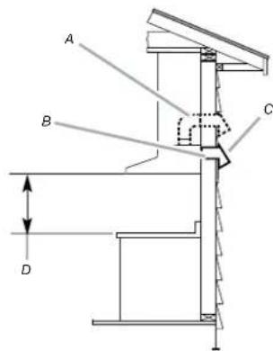
Rear discharge
A 90° elbow may be installed immediately above the hood.
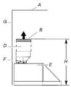
For Non-Vented (recirculating) Installations
If it is not possible to vent cooking fumes and vapors to the outside, the hood can be used in the non-vented (recirculating) version, fitting a charcoal filter and a plastic grid. Fumes and vapors are recycled through the a recirculation grid.
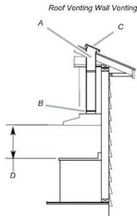
A. 6" (15.2 cm) round vent
B. 6" (15.2 cm) round transition
C. Roof cap
D. Installation height
Recirculating through the cabinet's top
A. Recirculation grid
B. 6" (15.2 cm) round vent
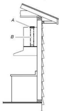
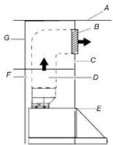
A. 6" (15.2 cm) round vent + 90° elbow
B. 3/4" x 10" (8.25 x 25.4 cm) rectangular vent
C. Wall cap
D. Installation height
Recirculating through the cabinet's front
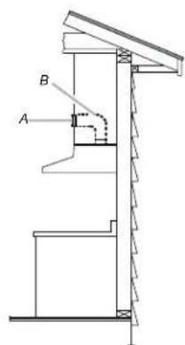
A. Recirculation grid B. 6" (15.2 cm) round vent + 90° elbow
Installation Requirements
Tools and Parts
Removing the packaging

CAUTION
Remove the carton carefully. Wear gloves to protect against sharp edges.

WARNING
Remove the protective film covering the product before putting into operation.
Parts supplied
- Hood assembly with blower and LED lamps already installed.
- Hardware bag with:
| Part Qty Part Qty | |||
 5x45 mm 5x45 mm | 4 |  5X8ZX 5X8ZX | 4 |
 4.5x13 mm 4.5x13 mm | 4 | 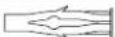 10 x 60 mm 10 x 60 mm | 4 |
 3.5x9.5 mm 3.5x9.5 mm | 2 |  Torx 10 adapter Torx 10 adapter | 1 |
 4.2x6 mm 4.2x6 mm | 7 |  Torx 20 adapter Torx 20 adapter | 1 |
 6" (15.2 cm) round transition 6" (15.2 cm) round transition | 1 | 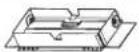 Rectangular transition 3/4" x 10" (8.3 x 25.4 cm) with back draft dampers Rectangular transition 3/4" x 10" (8.3 x 25.4 cm) with back draft dampers | 1 |
 Rear blower mounting bracket Rear blower mounting bracket | 1 | ||
pls/Materials required
- Level
- Drill with 1 14 (3.2 cm), 1/8 (3.2 mm), and 1/16 (4.8 mm) drill bits
- Pencil
- Wire stripper or utility knife
- Tape measure or ruler
- Pliers
• Caulking gun and weatherproof caulking compound - Vent clamps
• Jigsaw or keyhole saw - Flat-blade screwdriver
- Metal snips
• Phillips & Torx 20 screwdrive
Parts needed
• Home power supply cable
- 12 " (12.7 mm) UL listed or CSA approved strain relief
• 3 UL listed wire connectors
- 1 wall or roof cap
- Metal vent system
Dimensions and Clearances
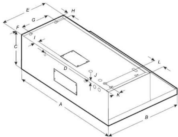
| NK30N7000USNK30N7000UG | NK36N7000USNK36N7000UG | |
| A 30" (76 cm) 36" (91.2 cm) | ||
| B | 1918" (50 cm) | |
| C | 914" (25 cm) | |
| D | 131316" (35 cm) | |
| E 12" (30.5 cm) | ||
| F | 2316" (5.5 cm) | |
| G | 714" (18.4 cm) | |
| H | 1116" (3 cm) | |
| I | 1116" (2.6 cm) | |
| J | 58" (1.6 cm) | |
| K | 1116" (4 cm) | |
| L | 3" (7.6 cm) 5 | 14" (14.6 cm) |
Accessories
| Model | NK30N7000US - NK36N7000USNK30N7000UG - NK36N7000UG |
| CharcoalFilter Kit | NK-AR050FNB/AA |
| RecirculationKit | NK-AF030FNB/AA |
Installation Clearances
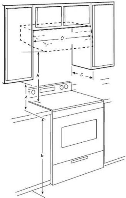
A. 18" (45.7 cm) min. clearance - upper cabinet to countertop
B. 24" (61.0 cm) min. for electric cooking surfaces
27" (68.6 cm) min. for gas cooking surfaces
36" (91.4 cm) suggested max. - bottom of range hood to cooking surface
C. 30" (76.2 cm) or 36" (91.4 cm) min. cabinet opening width
D. 12" (30.5 cm) min. cabinet depth
E. 36" (91.4 cm) base cabinet height
Installation Instructions
We recommend that a qualified technician install the range hood. It is the installer's responsibility to ensure the range hood complies with the installation clearances specified for the product.
Preparing the location
• We recommend you install the vent system before you install the hood.
- Before making cutouts, make sure there is proper clearance within the ceiling or wall for vent fittings.
- If the cabinet you are attaching the hood to is not mounted on the wall yet, it may be easier to attach the cutout to the bottom of the cabinet before mounting the cabinet on the wall.
- Disconnect power.
- Determine which venting method to use: roof or wall.
- Select a flat surface for assembling the range hood.
Place a covering over that surface.

WARNING
EXCESSIVE WEIGHT HAZARD
USE TWO OR MORE PEOPLE TO MOVE AND INSTALL THE RANGE HOOD. FAILURE TO DO SO CAN RESULT IN BACK OR OTHER INJURIES.
- Using 2 or more people, lift the range hood onto a covered surface.
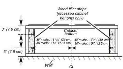
- If the cabinet has a recessed bottom, add wood filler strips on each side to fill in the space. Install screws to attach filler strips in the locations shown in the illustration at the top of the next column.
NOTE: All the screw locations must be measured from the cabinet's centerline.
- Determine and clearly mark a vertical centerline on the wall and cabinet in the area the vent opening will be made.
Determine the wiring hole location
Cut only one 1½" (3.2 cm) diameter wiring access hole.
To wire through the top:
Mark a line Distance "A" (See below) from the left of the centerline on the underside of the cabinet. Mark a point on this line that is 1 116 " (4 cm) from the back wall. Drill a 1 14 " (3.2 cm) diameter hole through the cabinet at this point.
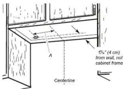
Distance A. 12" (30.5 cm) for 30" (76.2 cm) models 12¼" (31.1 cm) for 36" (91.4 cm) models
To wire through the wall:
Mark a line Distance "A" (See below) from the left of the centerline on the underside of the cabinet. Mark a point on this line that is 1" (2.54 cm) below the bottom of the cabinet. Drill a 1 14 " (3.2 cm) diameter hole through the wall at this point.
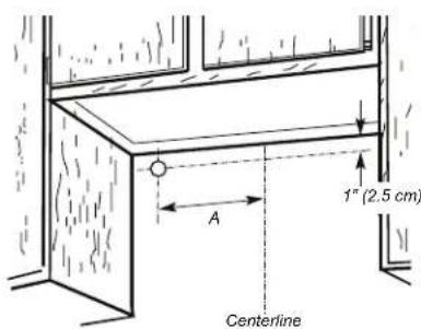
Distance A. 12" (30.5 cm) for 30" (76.2 cm) models 12¼" (31.1 cm) for 36" (91.4 cm) models
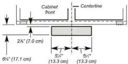
STYLE 1 - CUT OPENINGS FOR 3 14 X 10" (8.3 CM X 25.4 CM) RECTANGULAR VENT SYSTEM
Wall venting
To make a 4" x 10 ^1/2 " (10.2 cm x 26.7 cm) rectangle in the wall:
- Draw one line 2 ^3/4 (7.0 cm) and a second line 6 ^3/4 (17.1 cm) below the underside of the cabinet. Extend these lines through the centerline on the back wall.
- Draw lines 5¼" (13.3 cm) to the right and left of the centerline on the wall. Make sure these lines intersect with the lines you drew in Step 1.
- With the lines you drew as a guide, use a saber or keyhole saw to cut a rectangular opening in the wall for the vent.
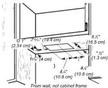
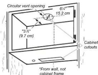
STYLE 2 - CUT OPENINGS FOR TOP VENT OUTLET (FROM RECTANGULAR TO 6" (15.2 CM) ROUND VENT SYSTEM) Roof venting
To make a 612 " x 812 " (16.5 cm x 21.6 cm) rectangle in the cabinet bottom:
- Draw a line 12 " (1.3 cm) from the back wall on the centerline of the underside of the cabinet, and then draw another line 612 " (16.5 cm) from the first line.
- Draw lines 4¼" (10.8 cm) to the right and left of the centerline on the underside of the cabinet.
- With the lines you drew as a guide, use a saber or keyhole saw to cut a rectangular opening for the vent.
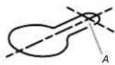
To make a circular vent opening on the underside of the cabinet top:
- Draw a centerline on the underside of the top of the cabinet.
- Draw a line 3 18 " (9.7 cm) from the back wall on the underside of the top of the cabinet. Make sure the line intersects with the line you drew in Step 1.
- Where the two lines intersect, use a compass or a circle template to draw a 6¼" (15.2 cm) circle.
- With the circle you drew as a guide, use a saber or keyhole saw to cut the circular vent opening.
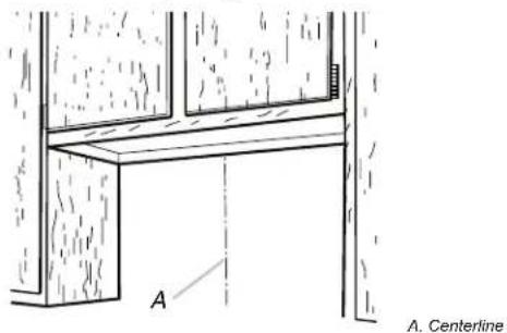
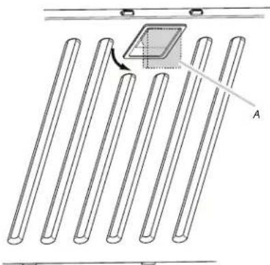
Non-Vented (recirculating) Installation through the Soffit/Cabinet
- Measure and mark the centerline of the cabinet to the soffit above.
- Measure from the bottom of the cabinet to the centerline of the where the vent will come through the soffit. Mark the location and use a saber saw or keyhole saw to cut a 5 ^3/4 " (14.6 cm) hole for the vent cover.
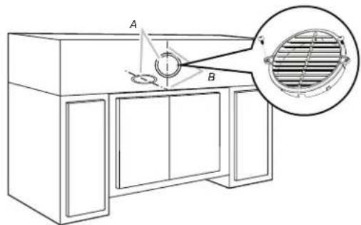
A. Vent cover B. Centerline
Install vent system
- Install the vent through the vent opening in the cabinet or wall. Complete the venting system according to the selected venting method. See the "Venting Requirements" section.
- Use caulking to seal the exterior wall or roof opening around the cap.
Installing the Range Hood
- Remove the baffle filters. See the "Range Hood Care" section.
- Remove the foam shipping pad from behind the blower motor.
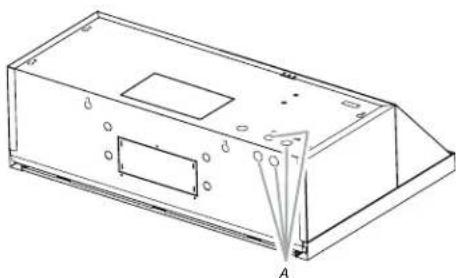
- Lift the range hood up under the cabinet and determine it's final location by centering it beneath the cabinet. Mark on the underside of cabinet the location of the 4 keyhole mounting slots on the range hood. Set the range hood aside on a covered surface.
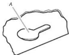
natural_image
Simple line drawing of a curved object inside a rectangular boundary, with no text or symbols present.A. Keyhole slot
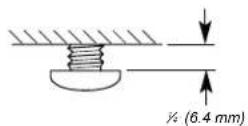
- Use a 18 " (3 mm) drill bit and drill 4 pilot holes as shown.
A. Drill pilot hole
- Install the 4 - 4.5 x 13 mm mounting screws in the pilot holes. Leave about 14 " (6.4 mm) space between the screw heads and cabinet to slide the range hood into place.
Connect Vent System
Vent connector installation
The range hood is factory set for use the top vent outlet.
Determine whether the range hood will be installed using either a top or rear vent connection.
Rear vent connector installation

NOTE
For rear venting, the blower motor position must be changed. You will need the rear motor mounting bracket that is included with the range hood.
- Remove the baffle filters. See the "Range hood care" section.
- Place the range hood on its back. Fit the vent system over the exhaust outlet.
- Disconnect the blower motor electrical connector from the electrical box connector.
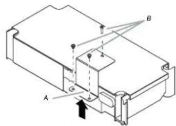
- Using a T20® adapter, remove the 4 screws holding the blower motor in place. Push up on the blower motor to disengage the tabs from range hood cavity back. Remove the blower motor and set it aside.
A. Range hood canopy (inside top)
B. Blower motor
C. Blower motor mounting screws
- Install the rear blower mounting bracket into the range hood and secure it with the (4) 4.2 x 8 mm screws.
A. Range hood canopy (inside back)
B. 4.2 x 8 mm screws (4)
C. Rear blower motor mounting bracket assembly
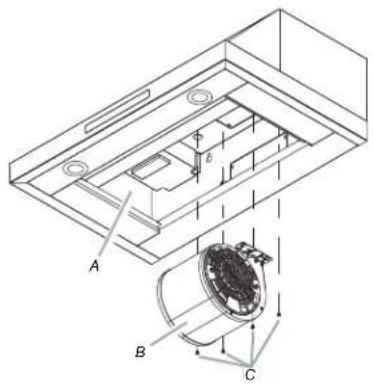
- Install the blower motor onto the rear motor mounting bracket (included with the range hood). Engage the motor mounting tabs with the keyhole slots in the rear mounting bracket and push down to secure. Install the 4 screws removed previously and tighten to secure motor bracket.

A. Rear motor mounting bracket
B. Motor mounting tabs (2)
C. Blower motor
D. Blower motor mounting screws (4)
- Reconnect blower motor electrical connector to the electrical box connector.
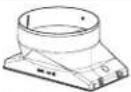
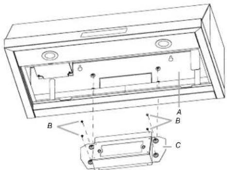
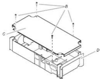
- Remove the rear vent knockout.
- Attach the 3 14 " x 10" (8.3 cm x 25.4 cm) rectangular vent damper using 3 - 4.2x8 mm vent transition mounting screws.
natural_image
Technical line drawing of a mechanical housing or enclosure with labeled components A, B, and C (no text or symbols beyond labels)A. Rear vent knockout
B. Rear rectangular transition knockout mounting screws (3)
C. Rear rectangular vent transition
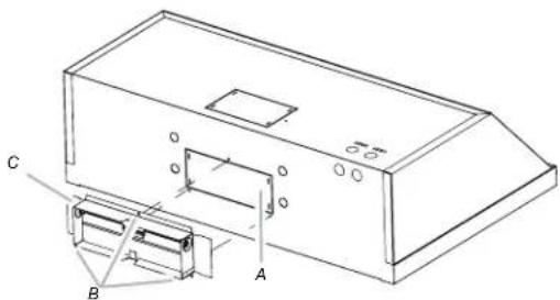
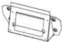
- Remove one of the round knockouts from the top or back of the range hood (depending on your wiring location) for the wiring strain relief and install a 12 " UL listed or CSA approved strain relief.
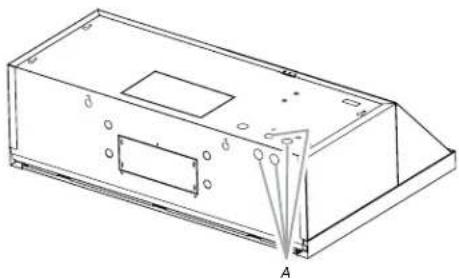
natural_image
Technical line drawing of a rectangular electronic device with mounting holes and a triangular base, labeled 'A' at the base (no text or symbols on the device itself)A. Round knockout
Mounting the Range Hood on a Cabinet
- Using 2 people, lift the range hood into it's final location. Feed enough electrical wire through the strain relief to make connections in the terminal box. Tighten the strain relief screws.
- Position the range hood so that the large end of the keyhole slots are over the mounting screws. Then, push the hood toward the wall so that the screws are in the neck of the slots. The hood should be against the wall. Tighten the mounting screws, making sure the mounting screws are in the narrow neck of the slots.
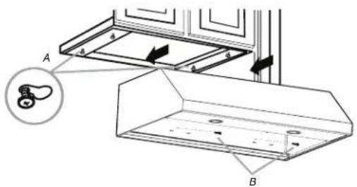
A. 4- mounting screws
B. Security screws
- Check that damper, if used, rotates up and down freely.
- Connect the ventwork to the hood. Seal joints with clamps to make secure and airtight.
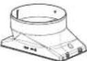
Top vent transition installation
- Remove the top vent knockout.
- Attach the round vent transition damper using 2 - 3.5x9.5 mm vent transition mounting screws.
- Remove the tape from the damper flap.
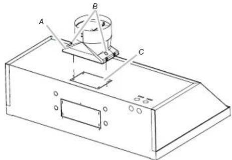
A. Top round vent transition
B. Top round vent transition mounting screws (2)
C. Top vent knockout
Mounting the Range Hood on the Wall
- Fix the wiring conduit of the hood.
- Slide the hood back against the wall. Tighten the mounting screws. Be sure the screw heads are in the narrow neck of the keyhole slot.
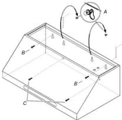
A. Mounting Screws
B. Upper security screws (Wall Installation)
C. Lower security screws (Wall Installation)
- Insert 2 screws into the upper security screw locations (see B in the image above). Tighten the screws.
- Insert 2 screws into the lower security screw location (see C in the image above). Tighten the screws.
- Connect the ductwork to the hood.
Electrical Connection
- Disconnect power.
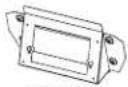
- Remove the bracket, and then the terminal box cover.
A. Bracket
B. Terminal box screws
C. Terminal box cover
D. Terminal box
- Remove the knockout in the terminal box cover, and then install a UL listed or CSA approved 12 " strain relief.
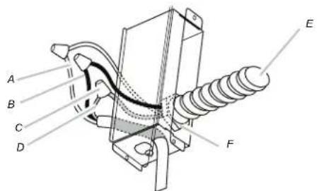
A. White wires
B. Black wires
C. UL listed wire connectors
D. Green (or bare) and yellow-green ground wire
E. Home power supply cable
F. UL listed or CSA approved 12 " strain relief
- Use UL listed wire connectors to connect the black wires (B) together.
- Use UL listed wire connectors to connect the white wires (A) together.

WARNING
Electrical Shock Hazard
Electrically ground blower.
Connect the ground wire to the green and yellow ground wire in the terminal box. Failure to do so can result in death or electrical shock.
- Connect the green (or bare) ground wire from the home power supply to the yellow-green ground wire (D) in the terminal box using UL listed wire connectors.
- Install the terminal box cover.
- Reconnect the power.
Complete the Installation
- Replace the baffle filters. See the "Range Hood Care" section.
- Check the operation of the range hood fan and lights.
See the "Range Hood Use" section. If the range hood does not operate, check to see whether a circuit breaker has tripped or a household fuse has blown. Disconnect the power and check the wiring connections.

NOTE
To get the most efficient use from your new range hood, read the "Range Hood Care" section.
Range Hood Description
The range hood is designed to remove smoke, cooking vapors, and odors from the cooktop area. For best results, start the hood before cooking and allow it to operate several minutes after cooking to clear all smoke and odors from the kitchen. The hood controls are located on the front of the hood.
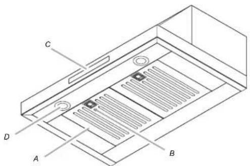
A. Baffle filter
B. Baffle filter handle
C. Blower and light controls
D. LED lamps
Range Hood Controls
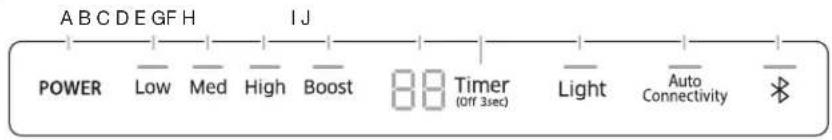
A. Power
B. Low Speed
C. Medium Speed
D. High Speed
E. Boost Speed
F. Timer Display
G. Timer
H. Light
I. Auto
Connectivity
J. Bluetooth
A. POWER
- Press the POWER button and the hood will turn on at default speed (Default Speed : Low).
- Press again and the hood will return to sleep mode.
B. LOW
- Press the LOW button and the hood will turn on at Low speed.
C. MED
- Press the MED button and the hood will turn on at Medium speed.
D. HIGH
- Press the HIGH button and the hood will turn on at High speed.
E. BOOST
- Press the BOOST button and the hood will increase to Maximum speed for 10 minutes.
• After 10 minutes, the hood will slow to High speed. - Normal mode
High & Boost CFM is the same (390CFM). - Power mode
High mode is 390 CFM and Boost mode is 600 CFM.
See Performance (CFM) Conversion on page 12.
F. Timer Display
• Shows the timer settings.
G. Timer
Setting the timer ON
- Press the Timer button to set the working time.
• Each time you press the Timer, you add 10 minutes to the displayed time, up to a maximum of 99 minutes. The hood will stay on for the amount of time you have set.
• After the Timer counts down to zero, the Timer LED light will start to blink.
- The Timer LED will blink for 5 seconds, and then the hood will turn off automatically.
Setting the timer OFF
- Press the Timer button for 3 seconds and the Timer function will turn off.
H. Light
- Press the Light button and the lamps will turn on.
- Press the Light button again and the lamps will turn off.
Sound
Muting / Unmuting the hood.
- Press and hold the Light button for 3 seconds to turn off the hood sounds.
- Press and hold again to turn on the sounds.
Cooktop and Range Hood Connectivity
This appliance has a feature which allows you to pair compatible Samsung cooktops and your hood via Bluetooth.
After you enable this function and pair your hood and a compatible cooktop, the hood fan will automatically come on at Low speed when you turn on a cooktop element. The hood fan will also shut off automatically when you turn off the cooktop elements.
In addition, after the hood and compatible cooktop are paired, you can download the Smart Things app to a mobile device, and then use the Smart Things app to:
• Monitor and control the On/Off status of the hood.
• Monitor and control the fan speed.
• Monitor and control the lights.
- Set the hood shut-off timer with the time-up alarm.
For more information about downloading the Smart Things app to your mobile device and using it to control your hood, visit: www.samsung.com.
J. ✘ Bluetooth connection (pairing)
- Press the Bluetooth button on hood. The pairing mode will be activated and the indicator on the Bluetooth button will blink.
- Press the Bluetooth button on cooktop.

NOTE
For a detailed description of the pairing method, see the user manual of a compatible Samsung cooktop.
- After the pairing process finishes, the Bluetooth light will stay lit and b_t appears in the display.
\* Bluetooth disconnection (Pairing reset)
- Press and hold the Bluetooth button on the hood for 3 seconds.
- The Bluetooth connection disconnects.
I. Auto Connectivity
The Auto Connectivity function lets you quickly connect the hood via Bluetooth with a compatible Samsung cooktop after the hood and cooktop have been paired. To turn the function on, press the Auto Connectivity button. To turn the function off and disconnect the hood and cooktop, press the Auto Connectivity button again.
While the hood and cooktop are connected, the hood fan will automatically come on at Low speed when you turn on a cooktop element. The hood fan will also shut off automatically when you turn off the cooktop elements. You will also be able to control the hood with the Smart Things app as described above.
- Press the Auto Connectivity button to activate the function.
- The hood will turn on/off automatically in conjunction with the cooktop.
- Press again to deactivate the function.
| Image | Remote Control by Smart Things App | Auto Connectivity | Hood Function |
| Auto Connectivity | XXO | ||
| Auto Connectivity | O X O | ||
| Auto Connectivity | O O O |

NOTE
These functions are only available if you have installed a compatible Samsung Bluetooth cooktop.
Performance (CFM) Conversion
- Press and hold the HIGH and BOOST button on the hood for 3 seconds to convert Blower performance.
- Normal mode: 40 appears in the display. The blower will operate normally (Max 390 CFM).
- Power mode: 60 appears in the display. The blower will operate at a more powerful level (Max 600 CFM).
CAUTION
We recommend that a qualified technician install the range hood to ensure it is compatible with Power mode. DO NOT activate Power mode if the installation is not compatible.
It is the installer's responsibility to ensure the range hood complies with the installation clearances specified for the product.
Power mode requires a custom air system.
The Custom Air System
- When using ventilation systems with greater than specified air movement CFM, review local building codes as they may require you to install a custom air system.
Consult a HVAC professional for specific requirements for you're area as CFM requirements can vary between locales.
- Consult a HVAC professional to select the correct CFM capacity range hood for your application. The CFM capacity depends on the range or cooktop BTU rating, size and location, size of the kitchen and the range hood ductwork in the kitchen.
Cleaning
IMPORTANT: Clean the hood and grease filters frequently according to the following instructions. Replace baffle filters before operating the hood.
Exterior surfaces:
- To avoid damage to the exterior surface, do not use steel wool or soap-filled scouring pads.
• Always wipe dry to avoid water marks.
Cleaning method:
• Liquid detergent soap and water or all-purpose cleanser.
- Wipe with damp soft cloth or nonabrasive sponge, and then rinse with clean water and wipe dry.
- Do not use cleaning agents containing bleach
Stainless steel baffle filter:
- Remove the filter by pulling the spring release handle, and then pulling down the filter.
natural_image
Diagram of parallel cylindrical rods arranged in rows with a small rectangular object labeled A inside, no text or symbols present.A. Spring release handle
- Wash the stainless steel baffle filter as needed in a dishwasher or hot detergent solution.
- To reinstall the filter, first make sure the spring release handle is toward the front. Insert the stainless steel filter into the upper track.
- Push in the spring release handle.
- Push up on the stainless steel filter, and then release the handle to latch it into place.

WARNING
When removing the filter, please hold it with both hands to make sure it does not fall.
Replacing the LED lamps
The LED lights are replaceable by a service technician only. See the support contact information in the Warranty section.
Accessories

NOTE
When used in recirculation mode, To Reduce the Risk of Fire and Shock use only conversion kit Models:
Recirculating kit: NK-AF030FNB/AA
Charcoal filter replacement: NK-AR050FNB/AA
Recirculating kit are not included with the hood. They must be ordered from your supplier or Samsung service center. Order the needed kit specifying your hood model and width size.
Recirculating kit
If it is not possible to vent cooking fumes and vapors to the outside, the range hood can be used in the non-vented (recirculating) version, using a charcoal filter. Recirculation Kit is available from the dealer or an authorized parts distributor.
A. Ceiling
B. Vent cover
C. Soffit
D. 6" (15.2 cm) vent
E. Range hood
F. Cabinet
G. Wall
H. 17" (43.2 cm) min.
vent cover height

NOTE
12" (30.5 cm) high cabinets without a soffit may allow the 6" (15.2 cm) vent and vent cover to be seen.
To replace charcoal filter:

NOTE
The maximum BTUs if you use carbon filter is 40 000. If you use the hood with the carbon filters on and it does not decrease the BTUs the engine can fail or generate an unsafe act.
- Cover the grille that covers the blower motor with the charcoal filter so that the slots on the filter correspond to the pins on the sides of the motor grille.
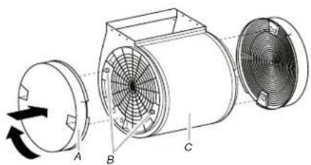
natural_image
Technical line drawing of a three-bladed industrial fan assembly with labeled components A, B, and C (no text or symbols beyond labels)A. Charcoal filter
B. Pins
C. Blower motor
- Turn the charcoal filter clockwise to lock it.
- Repeat steps 1-2 on the other filter.
SAMSUNG RANGE HOOD
Limited warranty to original purchaser
This SAMSUNG brand product, as supplied and distributed by Samsung Electronics America, Inc. (SAMSUNG) and delivered new, in the original carton to the original consumer purchaser, is warranted by SAMSUNG against manufacturing defects in materials and workmanship for a limited warranty period of:
ONE (1) YEAR PARTS AND LABOR
This limited warranty begins on the original date of purchase, and is valid only on products purchased and used in the United States. To receive warranty service, the purchaser must contact SAMSUNG for problem determination and service procedures. Warranty service can only be performed by a SAMSUNG authorized service center. The original dated bill of sale must be presented upon request as proof of purchase to SAMSUNG or SAMSUNG's authorized service center.
SAMSUNG will repair or replace this product, at our option and at no charge as stipulated herein, with new or reconditioned parts or products if found to be defective during the limited warranty period specified above. All replaced parts and products become the property of SAMSUNG and must be returned to SAMSUNG. Replacement parts and products assume the remaining original warranty, or ninety (90) days, whichever is longer.
In-home service will be provided during the warranty labor period subject to availability within the contiguous United States. In-home service is not available in all areas. To receive in-home service, the product must be unobstructed and accessible to service personnel. If during in-home service repair can not be completed, it may be necessary to remove, repair and return the product.
This limited warranty covers manufacturing defects in materials and workmanship encountered in normal, noncommercial use of this product and shall not apply to the following, including, but not limited to: damage which occurs in shipment; delivery and installation; applications and uses for which this product was not intended; altered product or serial numbers; cosmetic damage or exterior finish; accidents, abuse, neglect, fire, water, lightning or other acts of nature; use of products, equipment, systems, utilities, services, parts, supplies, accessories, applications, installations, repairs, external wiring or connectors not supplied or authorized by SAMSUNG which damage this product or result in service problems; incorrect electrical line voltage, fluctuations and surges; customer adjustments and failure to follow operating instructions, cleaning, maintenance and environmental instructions that are covered and prescribed in the instruction book; problems caused by pest infestations, and overheating by user.
THERE ARE NO EXPRESS WARRANTIES OTHER THAN THOSE LISTED AND DESCRIBED ABOVE, AND NO WARRANTIES WHETHER EXPRESS OR IMPLIED, INCLUDING, BUT NOT LIMITED TO, ANY IMPLIED WARRANTIES OF MERCHANTABILITY OR FITNESS FOR A PARTICULAR PURPOSE, SHALL APPLY AFTER THE EXPRESS WARRANTY PERIODS STATED ABOVE, AND NO OTHER EXPRESS WARRANTY OR GUARANTY GIVEN BY ANY PERSON, FIRM OR CORPORATION WITH RESPECT TO THIS PRODUCT SHALL BE BINDING ON SAMSUNG. SAMSUNG SHALL NOT BE LIABLE FOR LOSS OF REVENUE OR PROFITS, FAILURE TO REALIZE SAVINGS OR OTHER BENEFITS, OR ANY OTHER SPECIAL, INCIDENTAL OR CONSEQUENTIAL DAMAGES CAUSED BY THE USE, MISUSE OR INABILITY TO USE THIS PRODUCT, REGARDLESS OF THE LEGAL THEORY ON WHICH THE CLAIM IS BASED, AND EVEN IF SAMSUNG HAS BEEN ADVISED OF THE POSSIBILITY OF SUCH DAMAGES. NOR SHALL RECOVERY OF ANY KIND AGAINST SAMSUNG BE GREATER IN AMOUNT THAN THE PURCHASE PRICE OF THE PRODUCT SOLD BY SAMSUNG AND CAUSING THE ALLEGED DAMAGE. WITHOUT LIMITING THE FOREGOING, PURCHASER ASSUMES ALL RISK AND LIABILITY FOR LOSS, DAMAGE OR INJURY TO PURCHASER AND PURCHASER'S PROPERTY AND TO OTHERS AND THEIR PROPERTY ARISING OUT OF THE USE, MISUSE OR INABILITY TO USE THIS PRODUCT SOLD BY SAMSUNG NOT CAUSED DIRECTLY BY THE NEGLIGENCE OF SAMSUNG. THIS LIMITED WARRANTY SHALL NOT EXTEND TO ANYONE OTHER THAN THE ORIGINAL PURCHASER OF THIS PRODUCT IS NON-TRANSFERABLE AND STATES YOUR EXCLUSIVE REMEDY.
Some provinces or territories may or may not allow limitations on how long an implied warranty lasts, or the exclusion or limitation of incidental or consequential damages, so the above limitations or exclusions may not apply to you. This warranty gives you specific legal rights, and you may also have other rights which vary from state to state.
To obtain warranty service, please contact SAMSUNG at:
Limited warranty to original purchaser
This SAMSUNG brand product, as supplied and distributed by Samsung Electronics Canada, Inc. (SAMSUNG) and delivered new, in the original carton to the original consumer purchaser, is warranted by SAMSUNG against manufacturing defects in materials and workmanship for a limited warranty period of:
ONE (1) YEAR PARTS AND LABOR
This limited warranty begins on the original date of purchase, and is valid only on products purchased and used in Canada. To receive warranty service, the purchaser must contact SAMSUNG for problem determination and service procedures. Warranty service can only be performed by a SAMSUNG authorized service center. The original dated bill of sale must be presented upon request as proof of purchase to SAMSUNG or SAMSUNG's authorized service center.
SAMSUNG will repair or replace this product, at our option and at no charge as stipulated herein, with new or reconditioned parts or products if found to be defective during the limited warranty period specified above. All replaced parts and products become the property of SAMSUNG and must be returned to SAMSUNG. Replacement parts and products assume the remaining original warranty, or ninety (90) days, whichever is longer.
In-home service will be provided during the warranty labor period subject to availability within the contiguous Canada. In-home service is not available in all areas. To receive in-home service, the product must be unobstructed and accessible to service personnel. If during in-home service repair can not be completed, it may be necessary to remove, repair and return the product.
This limited warranty covers manufacturing defects in materials and workmanship encountered in normal, noncommercial use of this product and shall not apply to the following, including, but not limited to: damage which occurs in shipment; delivery and installation; applications and uses for which this product was not intended; altered product or serial numbers; cosmetic damage or exterior finish; accidents, abuse, neglect, fire, water, lightning or other acts of nature; use of products, equipment, systems, utilities, services, parts, supplies, accessories, applications,
installations, repairs, external wiring or connectors not supplied or authorized by SAMSUNG which damage this product or result in service problems; incorrect electrical line voltage, fluctuations and surges; customer adjustments and failure to follow operating instructions, cleaning, maintenance and environmental instructions that are covered and prescribed in the instruction book; problems caused by pest infestations, and overheating by user. SAMSUNG does not warrant uninterrupted or error-free operation of the product.
THERE ARE NO EXPRESS WARRANTIES OTHER THAN THOSE LISTED AND DESCRIBED ABOVE, AND NO WARRANTIES WHETHER EXPRESS OR IMPLIED, INCLUDING, BUT NOT LIMITED TO, ANY IMPLIED WARRANTIES OF MERCHANTABILITY OR FITNESS FOR A PARTICULAR PURPOSE, SHALL APPLY AFTER THE EXPRESS WARRANTY PERIODS STATED ABOVE, AND NO OTHER EXPRESS WARRANTY OR GUARANTY GIVEN BY ANY PERSON, FIRM OR CORPORATION WITH RESPECT TO THIS PRODUCT SHALL BE BINDING ON SAMSUNG. SAMSUNG SHALL NOT BE LIABLE FOR LOSS OF REVENUE OR PROFITS, FAILURE TO REALIZE SAVINGS OR OTHER BENEFITS, OR ANY OTHER SPECIAL, INCIDENTAL OR CONSEQUENTIAL DAMAGES CAUSED BY THE USE, MISUSE OR INABILITY TO USE THIS PRODUCT, REGARDLESS OF THE LEGAL THEORY ON WHICH THE CLAIM IS BASED, AND EVEN IF SAMSUNG HAS BEEN ADVISED OF THE POSSIBILITY OF SUCH DAMAGES. NOR SHALL RECOVERY OF ANY KIND AGAINST SAMSUNG BE GREATER IN AMOUNT THAN THE PURCHASE PRICE OF THE PRODUCT SOLD BY SAMSUNG AND CAUSING THE ALLEGED DAMAGE. WITHOUT LIMITING THE FOREGOING, PURCHASER ASSUMES ALL RISK AND LIABILITY FOR LOSS, DAMAGE OR INJURY TO PURCHASER AND PURCHASER'S PROPERTY AND TO OTHERS AND THEIR PROPERTY ARISING OUT OF THE USE, MISUSE OR INABILITY TO USE THIS PRODUCT SOLD BY SAMSUNG NOT CAUSED DIRECTLY BY THE NEGLIGENCE OF SAMSUNG. THIS LIMITED WARRANTY SHALL NOT EXTEND TO ANYONE OTHER THAN THE ORIGINAL PURCHASER OF THIS PRODUCT IS NON-TRANSFERABLE AND STATES YOUR EXCLUSIVE REMEDY.
Some provinces or territories may or may not allow limitations on how long an implied warranty lasts, or the exclusion or limitation of incidental or consequential damages, so the above limitations or exclusions may not apply to you. This warranty gives you specific legal rights, and you may also have other rights which vary from state to state.
To obtain warranty service, please contact SAMSUNG at:
Connectivity Cooktop / Hood Range 27
Entretien de la Hotte 29
Nettoyage 28
National Fire Protection Association
1 Batterymarch Park
Quincy, MA 02169-7471
CSA International
8501 East Pleasant Valley Road
Cleveland, OH 44131-5575
■ If the house has aluminum wiring, follow the procedure below:
| NK30N7000USNK30N7000UG | NK36N7000USNK36N7000UG | |
| A 30" (76 cm) 36" (91.2 cm) | ||
| B | 19 18 " (50 cm) | |
| C | 9 14 " (25 cm) | |
| D | 13 13 % (35 cm) | |
| E 12" (30.5 cm) | ||
| F | 2 316 " (5.5 cm) | |
| G | 7 14 " (18.4 cm) | |
| H | 1 16 " (3 cm) | |
| I | 1 116 " (2.6 cm) | |
| J | 58 " (1.6 cm) | |
| K | 1 16 " (4 cm) | |
| L 3" (7.6 cm) 5 | 14 " (14.6 cm) | |
Accessoires
| Modèle | NK30N7000US - NK36N7000USNK30N7000UG - NK36N7000UG |
| Kit de filtre a charbon | NK-AR050FNB/AA |
| Kit de Recyclage | NK-AF030FNB/AA |
natural_image
Architectural line drawing of a window frame with labeled section A (no text or symbols beyond label)A. Axe central
natural_image
Simple line drawing of a curved object inside a rectangular boundary, with a labeled point A pointing to it (no text or symbols beyond the label)A. Trou allongé
natural_image
Technical line drawing of a rectangular electronic device with mounting holes and a triangular base, labeled 'A' at the base (no text or symbols on the device itself)A. Opercule amovible rond
natural_image
Technical line drawing of a mechanical fan assembly with labeled components A, B, and C (no text or symbols beyond labels)National Fire Protection Association
1 Batterymarch Park
Quincy, MA 02169-7471
CSA International
8501 East Pleasant Valley Road
Cleveland, OH 44131-5575
 5x45 mm 5x45 mm | 4 |  5.4x75 mm screws(for 10x60 mm wall anchors) 5.4x75 mm screws(for 10x60 mm wall anchors) | 4 |
 4.5x13 mm 4.5x13 mm | 4 |  10 x 60 mm 10 x 60 mm | 4 |
 3.5x9.5 mm 3.5x9.5 mm | 2 |  Torx 10 adapter Torx 10 adapter | 1 |
 4.2x8 mm 4.2x8 mm | 7 |  Torx 20 adapter Torx 20 adapter | 1 |
 6" (15.2 cm) round transition 6" (15.2 cm) round transition | 1 | 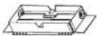 Rectangular transition 3/4" x 10" (8.3 x 25.4 cm) with back draft dampers Rectangular transition 3/4" x 10" (8.3 x 25.4 cm) with back draft dampers | 1 |
 Rear blower mounting bracket Rear blower mounting bracket | 1 |
5x45 mm
.4x75 mm screws
for 10x60 mm wall
anchors)
4.5×13 mm
10 x 60 mm
3.5×9.5 mm
Torx 10 adapter
4.2×8 mm
Torx 20 adapter
6" (15.2 cm) round
transition
Rectangular transition
3/4"×10"(8.3×25.4
cm) with back draft
dampers
Rear blower
mounting bracket
| NK30N7000USNK30N7000UG | NK36N7000USNK36N7000UG | |
| A 30" (76 cm) 36" (91.2 cm) | ||
| B | 19 18 " (50 cm) | |
| C | 9 14 " (25 cm) | |
| D | 13 13 % (35 cm) | |
| E 12" (30.5 cm) | ||
| F | 2 316 " (5.5 cm) | |
| G | 7 14 " (18.4 cm) | |
| H | 1 16 " (3 cm) | |
| I | 1 116 " (2.6 cm) | |
| J | 5 18 " (1.6 cm) | |
| K | 1 16 % (4 cm) | |
| L 3" (7.6 cm) 5 | 14 " (14.6 cm) | |
Accesorios
| Modelo | NK30N7000US - NK36N7000USNK30N7000UG - NK36N7000UG |
| Kit de Filtro de Carbón | NK-AR050FNB/AA |
| Kit Recirculante | NK-AF030FNB/AA |
natural_image
Architectural line drawing of a window frame structure with labeled point A (no text or symbols beyond label)A. Línea central
Distancia A. 12" (30.5 cm) para modelos de 30" (76.2 cm) 12¼" (31.1 cm) para modelos de 36" (91.4 cm)
A. Vent cover B. Centerline
natural_image
Simple line drawing of a bowl with a spoon inside, no text or symbols present- Remove one of the round knockouts from the top or back of the range hood (depending on your wiring location) for the wiring strain relief and install a 12 " UL listed or CSA approved strain relief.
natural_image
Technical line drawing of a rectangular electronic device with mounting holes and a triangular base, labeled A (no text or symbols on the diagram itself)A. Precortes removibles
natural_image
Diagram of parallel tubes arranged in rows with a small inset showing a square component, labeled 'A' (no text or symbols on tubes)F. Cabinet
G. Wall
H. Altura mínima del gabinete:
12" (30.5 cm)

NOTA
natural_image
Technical line drawing of a three-bladed industrial fan assembly with labeled components A, B, and C (no text or symbols beyond labels)A. Filtro de Carbón
B. Pines
C. Motor