
Escalade IQ (2026) - Car CADILLAC - Free user manual and instructions
Find the device manual for free Escalade IQ (2026) CADILLAC in PDF.


User questions about Escalade IQ (2026) CADILLAC
0 question about this device. Answer the ones you know or ask your own.
Ask a new question about this device
Download the instructions for your Car in PDF format for free! Find your manual Escalade IQ (2026) - CADILLAC and take your electronic device back in hand. On this page are published all the documents necessary for the use of your device. Escalade IQ (2026) by CADILLAC.
USER MANUAL Escalade IQ (2026) CADILLAC
ESCALADE IQ/ESCALADE IQL VEHICLE REFERENCE INFORMATION


85625870 A
2026

FSC
MIX
Paper | Supporting responsible forestry
California Proposition 65 Warning

WARNING
Operating, servicing and maintaining a passenger vehicle or off-highway motor vehicle can expose you to chemicals including engine exhaust, carbon monoxide, phthalates, and lead, which are known to the State of California to cause cancer and birth defects or other reproductive harm. To minimize exposure, avoid breathing exhaust, do not idle engine except as necessary, service your vehicle in a well-ventilated area and wear gloves or wash your hands frequently when servicing your vehicle. For more information go to www.P65Warnings.ca.gov/passenger-vehicle.
Contents
Introduction ....1
Door Locks (In Case of Dead Battery) ......2
Hood 2
Seat Belts 7
Airbag System 7
Child Restraint Systems 7
Windshield Wiper/Washer 7
Warning Lights, Gauges, and Indicators ....7
Exterior Lamp Controls 8
Hazard Warning Flashers 8
Driver Behavior 8
Brakes 8
Traction Control/Electronic Stability Control 9
Driver Assistance Systems ....9
Plug-In Charging 9
Underhood Compartment Overview ..... 14
Tire Sealant and Compressor Kit ....15
Jump Starting - North America ......20
Transporting a Disabled Vehicle ....23
Customer Assistance for Text Telephone (TTY) Users ....24
Roadside Assistance Program ....24
Reporting Safety Defects to the United States Government 24
Reporting Safety Defects to the Canadian Government 25
Reporting Safety Defects to General Motors 25
Introduction
This document includes vehicle reference information for your vehicle. This document does not replace your Owner's Manual, which includes other important information, including warnings and precautions.
For complete operating information and instructions, see the Owner's Manual on the myCadillac app in the vehicle infotainment system, at www.cadillac.com, or on the myCadillac mobile app.
To verify your vehicle has a downloaded Owner's Manual in the infotainment system, go to the myCadillac app, touch the Settings icon, and touch Owner's Manual Details.
If your vehicle has a downloaded Owner's Manual, the downloaded version is accurate at the time of installation. To ensure you are viewing the most up-to-date, connected
version of the Owner's Manual, accept the Terms and Conditions and have an active Wi-Fi or data connection. Up-to-date versions of the Owner's Manual are also accessible at www.cadillac.com and on the myCadillac mobile app.
To view digital versions or to order printed versions of the Owner's Manual or warranty information, or to view additional vehicle information, scan the code below or visit cadillac.com/support/vehicle/manuals-guides (U.S.) or cadillaccanada.ca/en/support/vehicle/manuals-guides (Canada):


United States Canada
Keep this manual in the vehicle for quick reference.
Door Locks (In Case of Dead Battery)
Driver Door Key Lock Cylinder Access (In Case of Dead Battery)
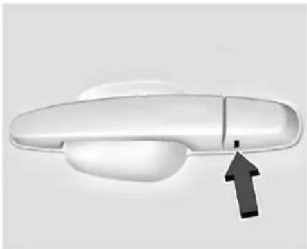
To access the driver door key lock cylinder and unlatch the door:
natural_image
Close-up of a white car door handle with a black arrow pointing to the side (no text or symbols visible)Sample Shown, Your Vehicle May Differ
- Insert the mechanical key into the slot at the bottom of the handle and push upward all the way until the cover frees. Do not pry or pull on the key.
-
Remove the cover.
-
Insert the mechanical key in the cylinder.
- Turn the mechanical key clockwise until it stops.
- Slowly turn the mechanical key counterclockwise while pulling the handle to unlatch the door.
- Repeat steps 4 and 5 if the door does not fully open.
To replace the cap:
- Align the top edge of the cover to the handle.
- Turn downward to snap cover into position.
- Check to ensure cap is fully seated.
Hood

Warning
You or others could be injured if caught in the path of the power hood. Always supervise the operation of the power hood until it is fully opened or closed and keep hands and other body parts away from the hood when in use.
Clear any snow from the hood before opening.
Power Hood Operation
The vehicle must be in P (Park), doors unlocked, or the remote key in range of the vehicle to operate the power hood.
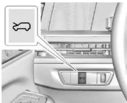
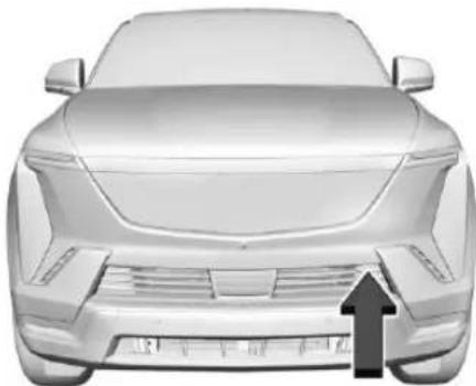
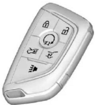
To open or close the power hood, press on the instrument panel, the touchpad on the front fascia, or the remote key.
To turn this feature on or off, select Settings > Vehicle > Comfort and Convenience > Power Hood Opening.
natural_image
Interior view of a car showing the dashboard and side panel with a traffic sign icon (no text or symbols on the main components)- To open the hood, press 📋 on the instrument panel to the left of the steering wheel once. To stop the hood while it is opening, press 📋 once.
- To close the hood, press and hold 📋 until the hood is closed. Releasing the button will stop the hood motion.
natural_image
Front view of a modern electric car with a black upward arrow indicating speed (no text or symbols visible)- To open or close the hood, press the touchpad on the front fascia once. The remote key must also be within 1 m (3 ft) if the vehicle is locked. To stop the hood while in motion, press the touchpad.
natural_image
Close-up of a white remote control key with buttons and icons (no readable text or symbols)- Press twice ^2 to open the hood. To stop the hood while opening, press ^2 once. To open or close the remote key must be within 30 m (100 ft). The vehicle must be in P (Park). See your owner's manual.
- To close the hood, press twice and hold until the hood closes. While closing, releasing the button will stop the hood motion.
Hands-Free Operation

Warning
You or others could be injured if caught in the path of the power hood. Make sure there is no one in the way of the hood as it is opening and closing.
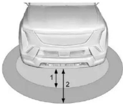
If equipped, the hood may be opened with a remote key by entering the front authentication zone from outside the approach zone. Both zones are located near the front of the vehicle. The vehicle must be approached from the front for the system to operate. See your owner's manual.
Entering the authentication zone at the front of the vehicle with the remote key will sound a notification and the taillights will flash. The hood will open automatically if the remote key remains in the authentication zone for several seconds.
natural_image
3D rendering of a car's rear bumper and side profile (no text or symbols)- Authentication Zone (1 m (3 ft))
- Approach Zone (3 m (9 ft))
To cancel the feature after entering the authentication zone, the user may perform a single press of the button, step out of the authentication zone, or, if equipped and enabled, press the exterior hood switch. The hands-free feature will not operate while the eTrunk is moving. To stop the hood while in motion, use any of the hood switches.
The hands-free feature can be deactivated. To turn on or off, from the infotainment screen, select Settings > Vehicle > Comfort and Convenience > Hands-Free Exterior Storage.
For some vehicles, this feature can be turned on and off using the touchpad while the remote key is in the authentication zone. To do this, press and hold the touchpad for several seconds. Upon successfully enabling or disabling the feature using this method, the vehicle taillights will flash.
Troubleshooting Hands-Free Operation
If the feature does not operate, the remote key may be in a muted state. Press any button on the remote key or any exterior vehicle switch to unmute the remote key.
The feature will be unavailable until the remote key has been out of the approach zone for more than twenty seconds if any of the following occur:
- After successfully opening the eTrunk using the hands-free feature.
- If the key enters the approach zone but does not enter the authentication zone within a short period of time.
- If the user has cancelled the feature by using the button, the exterior eTrunk switch, or stepping out of the authentication zone for more than a few seconds.
The hands-free feature will not be active under these conditions:
- The feature is set to OFF in Settings > Vehicle > Comfort and Convenience > Hands-Free Exterior Storage.
- If the vehicle is equipped with the side approach feature, this closure hands-free may not work due to conflict with other hands-free approach zones.
• Vehicle battery is low.
• Power eTrunk is set to OFF. - If Power eTrunk is later re-enabled, Hands-Free Opening will not automatically enable and must be re-enabled separately.
• A remote key is inside the vehicle.
• The vehicle is not in P (Park). - The vehicle remains parked for more than several days, with no remote key use or Keyless Access operation. To re-enable, press any button on the remote key or open and close any vehicle door.
Open Settings
Maximum
The hood opens to the fully open position. Use caution in this mode to avoid hitting overhead obstructions.
Custom
The hood opens to a pre-programmed height below maximum position. To adjust the hood open height, manually move the hood to a desired position. The hood cannot be set below a preset minimum programmable height. After placing the hood at your desired height, press the touch pad on the front fascia until the exterior lights flash and a chime sounds. If no exterior lights flash or chimes sound, then the height adjustment may be too low.
The hood is restricted to only open to a default height when the vehicle is on a steep downhill grade.
Off (Manual Operation)
Press and release the touch pad on the front fascia. Lift the hood to open to a desired height. To close the hood, pull the hood down until it is secured in the latch. When the hood is in the latch, the hood will automatically close.
Obstacle Detection Features
If the hood encounters an obstacle during a power open or close cycle, the hood will automatically reverse direction and move away from the obstacle. After removing the obstruction, the power hood operation can be used again.
If the vehicle is locked while the hood is closing and an obstacle is encountered that prevents the hood from completely closing, the horn will sound an alert that the hood did not close.
Falling Hood Detection
If the power hood encounters excess weight or a possible mechanical failure, a repetitive chime will sound and the hood will close automatically after a power opening cycle. Interfering with the power hood motion or manually closing the hood too quickly may activate the falling hood detection feature. Allow the hood to complete its operation and wait a few seconds before manually closing the hood.
If the hood continues to automatically close after opening, see your dealer for service before using the power hood.
Operating the Hood when there is no Electrical Power

Warning
Do not drive the vehicle if the hood is not latched completely. The hood could open fully, block your vision, and cause a crash. You or others could be injured. Always close the hood completely before driving.
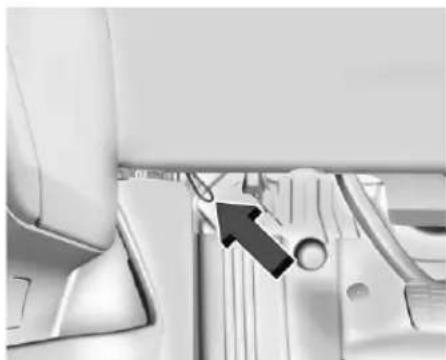
The manual release cable should only be used for service and/or emergency use, such as loss of vehicle electrical power. Do not store any cargo in the area near the hood release cable.
natural_image
Interior view of a car showing the dashboard and seat area with a black arrow pointing to a component (no text or symbols visible)To open the hood:
-
Firmly pull the hood release cable twice to release the hood. It is on the lower left side of the instrument panel.
-
Go to the front of the vehicle and lift the hood to the desired height.
To close the hood:
-
Before closing the hood, make sure all cargo is properly stowed and does not go above or across the hood seal.
-
Pull the hood down until it is secured in the latch.
-
Check to make sure the hood is latched completely. Push down on the hood to latch if it does not latch completely. Repeat this step with additional force if necessary.
When the hood is not latched, a message will display on the Driver Information Center (DIC) and the vehicle will not be able to shift out of park. To override this function, press and hold the brake pedal until the DIC message shifter unlock complete is displayed. The vehicle's speed will be limited to 42 km/h (26 mph) when the hood is not completely closed.
If the vehicle has lost power, and the hood is open when the power is restored, the power hood and power closing latch will not operate. To allow powered hood operation again, the hood must be manually closed and fully latched.
Emergency Hood Release Button

Warning
The emergency hood release button inside the underhood compartment will not function when the battery is disconnected
(Continued)
Warning (Continued)
or depleted. To avoid personal injury or death, always keep the hood fully closed and latched when storing the vehicle. If the hood is not latched, a person could climb into the underhood compartment and inadvertently close the hood. People should never climb inside the underhood compartment. Never shut the hood when a person is inside.
natural_image
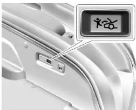
Close-up of a device's interior panel with a highlighted indicator box showing a person silhouette (no text or symbols on the device itself)The underhood compartment is equipped with a glow-in-the-dark emergency hood release button. This button will glow following exposure to light. Press the button to open the hood from inside the underhood compartment.
Always make sure every vehicle occupant has properly adjusted their seat and head restraint, positioned and fastened their seat belt, and infants and young children are secured in appropriate child restraints. See your Owner's Manual for complete information on Seating and Restraints, Top Tether, and the LATCH System.
Your vehicle is equipped with airbags, marked in your vehicle with the word "AIRBAG". Airbags work together with seat belts and other systems to help protect occupants in a crash. See your Owner's Manual for complete information on a seating, restraints, and airbags.
Child Restraint Systems
According to accident statistics, children are safer when properly restrained in a rear seating position. Infants and young children should always be secured in an appropriate child restraint. See your Owner's Manual for more information about child restraint usage, top tethers, and LATCH systems.
Windshield Wiper/Washer
Your vehicle is equipped with windshield wipers to help maintain visibility in inclement weather conditions. See your Owner's Manual for complete information about these systems.
With the vehicle on, move the windshield wiper lever to select the wiper speed.
For a single wipe, briefly move the wiper lever down. For several wipes, hold the wiper lever down.
Pull the windshield wiper lever toward you to spray windshield washer fluid and activate the wipers. The wipers will continue until the lever is released or the maximum wash time is reached. When the windshield wiper lever is released, additional wipes may occur depending on how long the windshield washer has been activated.
Clear snow and ice from the wiper blades and windshield before using them. If frozen to the windshield, carefully loosen or thaw them. Damaged blades should be replaced.

Warning
In freezing weather, do not use the washer until the windshield is warmed. Otherwise the washer fluid can form ice on the windshield, blocking your vision.

Warning
Before driving the vehicle, always clear snow and ice from the hood, windshield, washer nozzles, roof, and rear of the vehicle, including all lights and windows. Reduced visibility from snow and ice buildup could lead to a crash.
Warning lights, gauges, and indicators can alert you to an issue with your vehicle. Some warning lights display briefly to show that they are working when you start the vehicle. However, if a warning light persists while driving, or if a gauge shows there may be a problem, be sure to refer to the sections under "Warning Lights, Gauges, and Indicators."
Paying attention to your vehicle's warning lights, gauges, and indicators and promptly addressing any issues may help you to
prevent an expensive repair or personal injury. Postponing repairs can be costly and even dangerous.
Exterior Lamp Controls
Your vehicle is equipped with exterior lighting to help maintain visibility in dark and inclement weather conditions. See your Owner's Manual for complete information about these systems.
The headlight controls are part of your vehicle's virtual touch displays. Touch the light symbol on the infotainment screen, the control panel of the Driver Information Center (DIC), or the center console screen, to operate the headlights.
Hazard Warning Flashers
Your vehicle is equipped Hazard Warning Flashers to help increase your visibility in adverse conditions. See your Owner's Manual for complete information about these systems.
⚠️: Press this button on the center stack, center console, or overhead console to make the front and rear turn signal lamps flash on and off. This warns others that you are having trouble. Press again to turn the flashers off.
The turn signals do not work while the hazard warning flashers are on.
The hazard warning flashers turn on automatically if the airbags deploy.
Driver Behavior
Distracted, Drowsy, and Impaired Driving

Warning
Drinking alcohol or taking drugs and then driving is very dangerous. Your reflexes, perceptions, attentiveness, and judgment can be affected by even a small amount of alcohol or drugs. You can have a serious — or even fatal — collision if you drive after drinking or taking drugs.
Do not drive while under the influence of alcohol or drugs, or ride with a driver who has been drinking or is impaired by drugs. Find alternate transportation home; or if you are with a group, designate a driver who will remain sober.
Do not attempt to operate a vehicle if impaired in any way. This includes if under the influence of drugs or alcohol, exhibiting exhaustion, or while distracted.
Traveling with Children and Pets

Warning
Never leave a child, a helpless adult, or a pet alone in a vehicle, especially with the windows closed in warm or hot weather. They can be overcome by the extreme heat and suffer permanent injuries or even death from heat stroke.
If traveling with children, helpless adults, or pets, do not leave them unattended in the vehicle at any time. Always ensure to check for children, helpless adults, or pets before exiting the vehicle.
See your Owner's Manual for important information about your vehicle's braking systems, including the Antilock Braking System, which can help prevent a braking skid and maintain steering while braking hard.
Traction Control/Electronic Stability Control
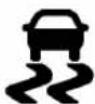
The vehicle has a Traction Control System (TCS) and StabiliTrak/Electronic Stability Control (ESC). These systems help limit wheel spin and assist the driver in maintaining control, especially on slippery road conditions.
If equipped, this vehicle may have features that work together to help avoid crashes or reduce crash damage while driving, backing, and parking. Read the owner's manual for more important feature limitations and information before using these systems.
Plug-In Charging
Caution
To avoid damage to the vehicle, make sure the charging cord plug is in good condition, is not worn or damaged, and is connected securely to the vehicle's charging port. If vehicle charging is intermittent, disconnect the cord and inspect for damage. An excessively worn or damaged AC or DC charging cord plug may result in an intermittent connection and potential damage to the vehicle's charging port.
Plug-in charge times vary based on the battery condition, charge level, outside temperature, and charge station capability. See your owner's manual for charge mode selection.
Do not allow the vehicle to remain in temperature extremes for long periods without being driven or plugged in. When temperatures are below 0 °C (32 °F) and above 32 °C (90 °F), plug in the vehicle to maximize high voltage battery life.
In extreme temperature conditions, a full charge will take additional time.
Charging slows down as the battery recharges. Charge the battery to 80% for daily driving, or when driving in mountainous terrain. The vehicle can be charged above 80% for long trips when not driving in mountainous terrain.
GM recommends the following:
- Unless your drive requires a full charge, charge the high voltage battery to 80% or less.
- Avoid allowing the high voltage battery to fall below 20% charged, if possible. See your owner's manual.
- If your route includes steep mountain terrain or if you are towing a trailer, it is important that your battery charge level is 80% or less to maximize regenerative braking performance.
It is normal to hear fans, pumps, and electrical devices clicking while the vehicle is turned off and charging.
The vehicle does not require indoor charging area ventilation before, during, or after charging.
The vehicle cannot be driven while the charge cord is plugged into the vehicle.

Warning
Use of charge cord adaptors may cause electrical overheating, resulting in vehicle damage or personal injury. Only use GM approved adaptors with the charge cord.
natural_image
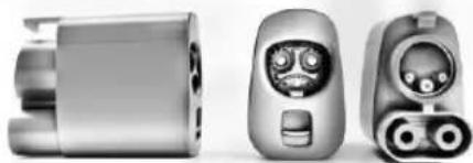
Three grayscale product views of a mobile phone device, front, side, and top (no visible text or symbols)To charge your vehicle, it may be necessary to use a special adapter to match the format of the charger you intend to use. The most common adapter for GM vehicles is a North American Charging Standard on a DC Fast Charger to CCS (the connector on your vehicle). If you use an adapter which is not sold, provided, or approved by General Motors and it causes damage to your vehicle's battery, said damage would not be covered under warranty.
There are several infotainment screens that will display depending on the current charging status. See your owner's manual.
Charging Override
A CHARGING OVERRIDE/INTERRUPTION OCCURRED message may display to indicate that a charging override or interruption has occurred due to one or more of the following events:
- Override of the charge settings by the owner.
- Unintended interruption of AC power at the vehicle's charge port.
- Interruption of charging by the utility company.
AC Charging
If equipped, a loss of AC power alert may sound briefly if AC power is lost for over one minute. This sound alert can be turned off. See your owner's manual.
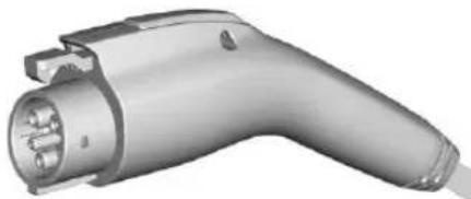
natural_image
3D rendering of an electric vehicle charging plug (no text or symbols visible)AC Charge Cord Vehicle Plug
To Start AC Charging
- Put the vehicle in P (Park).
natural_image
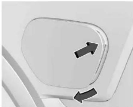
Close-up of a car door panel with two directional arrows indicating movement (no text or symbols)- The charge port door is on the rear driver side of the vehicle. Push and release the rearward edge of the charge port door to open it.
In cold weather conditions, ice may form around the charge port door. Remove ice from the area before attempting to open or close the charge port door. -
Open the liftgate, lift the load floor cover, and remove the charge cord.
-
Plug the charge cord into the electrical outlet. To verify the charge cord status, see your owner's manual. For instructions to set cord limit settings for a charge session, see your owner's manual.
- Plug in the AC charge cord into the vehicle charge port. Make sure the AC vehicle plug is fully connected to the AC charge port. If it is not properly connected, the vehicle may not charge.
- Verify that the charge status light turns on and an audible chirp occurs. See your owner's manual.
To End AC Charging
- Unlock the charge cord from the vehicle by pressing the button on the top of the charge cord plug. Unplug the charge cord from the vehicle. The charge port door will automatically close when the charge cord is unplugged.
natural_image
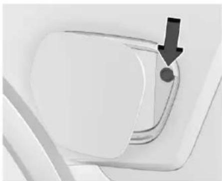
Close-up of a white object with a black arrow pointing to a circular feature, no visible text or symbols.- Press the button to manually close the charge port door.
- Unplug the charge cord from the electrical outlet.
- Place the charge cord into the storage compartment.
DC Charging
DC Charging Station Hardware

Warning
Do not use the charging station if the handle has defects such as cracks, exposed wires, burnt or missing pins, or any other damage. A damaged handle may result in personal injury and/or damage to the vehicle, the charging port or other property.
You can charge the vehicle using DC charging equipment typically found at service stations and other public locations.
This vehicle is compatible with a Combined Charging System 1 (CCSI) connector. Check the charging station DC vehicle plug for compatibility with the DC charge port on this vehicle.
When recharging at a DC charge station, the charging cable connected to the vehicle must be less than 10 m (33 ft) in length to meet functionality and regulatory requirements.
For maximum charging performance, and to prevent charging interruptions or damage to the high voltage battery and vehicle:
- Remove your hands from the charging handle once it has been plugged in. If not done, this can cause a charging interruption.
- Ensure that the charge cord plug clicks.
Follow the steps listed on the charging station to perform a DC vehicle charge.
If for any reason DC charging does not begin or is interrupted, check the DC charging station display for messages. Unplug the cord to restart the DC charging process.
To Start DC Charging
| Caution |
| Do not attempt to disconnect the DC vehicle plug while charging is active. This action may damage the vehicle or charging station hardware. |
- Put the vehicle in P (Park).
natural_image
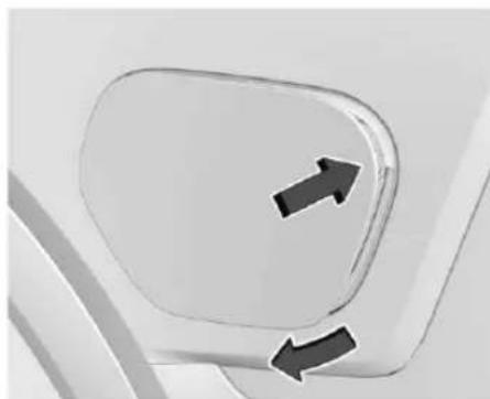
Close-up of a car door panel with two black arrows pointing to the side (no text or symbols visible)- Push and release the rearward edge of the charge port door to open it. In cold weather conditions, ice may form around the charge port door. Remove ice from the area before attempting to open or close the charge port door.
natural_image
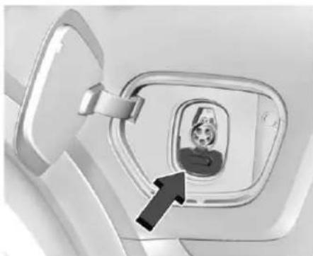
Close-up of a car window with a person inside, showing a lock and arrow pointing to the window (no text or symbols visible)- Unlatch the DC charging dust cover and lower it fully.
- Plug in the DC charge cord into the vehicle charge port. Make sure that the DC vehicle plug is fully connected to the DC charge port. If it is not properly connected, the vehicle may not charge. Check the Driver Information Center (DIC) to make sure the vehicle plug is connected properly.
- Follow the steps listed on the charging station to start charging.
-
When charging is active, the DC vehicle plug is locked to the DC charge port and cannot be disconnected.
-
Verify that the charge status light turns on and an audible chirp occurs. See your owner's manual.
To End DC Charging
When the vehicle is fully charged, charging automatically stops and the plug unlocks. You can also manually stop charging using the button on the DC vehicle plug, the controls at the charging station, or by tapping "Stop" on the Charging screen on the infotainment display.
If the vehicle plug does not unlock from the vehicle charge port after a charge, contact Roadside Assistance or use the emergency manual charge cord release. See Roadside Assistance Program 24 and "Emergency Manual Charge Cord Release" later in this section.
-
Unplug the DC vehicle plug from the DC charge port on the vehicle and close the dust cover.
-
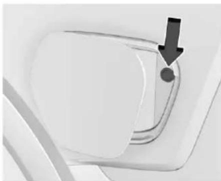
The charge port door will automatically close when the charge cord is unplugged.
natural_image
Close-up of a white plastic door with a black arrow pointing to a circular detail (no text or symbols visible)- Press the button to manually close the charge port door.
Emergency Manual Charge Cord Release
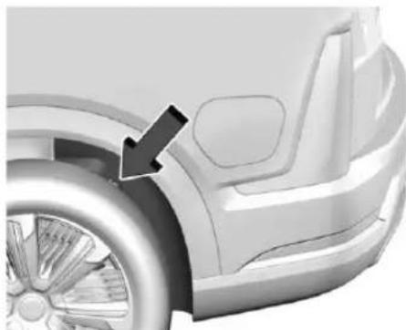
The vehicle is equipped with an emergency manual charge cord release in the event the DC vehicle plug does not release normally.
natural_image
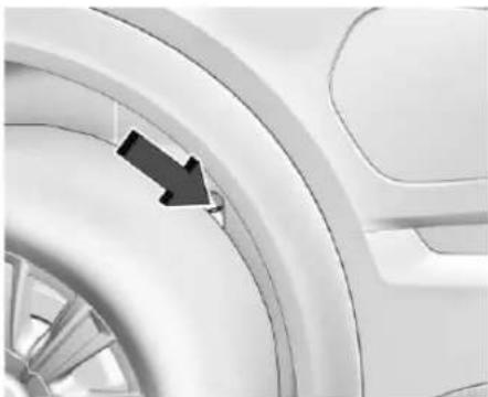
Side view of a car's front wheel and side panel, showing a black arrow pointing to the wheel (no text or symbols present)- Reach around the panel to find the emergency manual charge cord release.
natural_image
Close-up of a car wheel rim with a black arrow pointing to the edge (no text or symbols visible)- Pull the emergency manual charge cord release handle. The DC charge cord will release.
To Stop AC or DC Charging
Use the controls on the charging station to stop the charge process at any time.
To stop charging when inside the vehicle, use the Stop Charge button on the Charging screen. See "Active Charging" in your owner's manual.
Underhood Compartment Overview

Warning
You or others could be injured if caught in the path of the power hood. Make sure there is no one in the way of the hood as it is opening and closing.
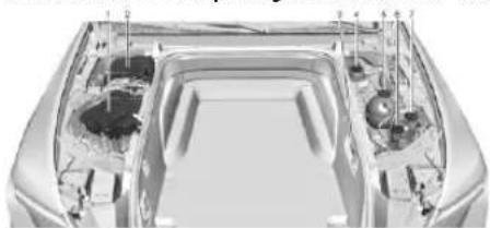
There are several items you should check periodically located under the hood.
For instructions on opening the hood, see H ood ↩ 2.
natural_image
Top-down view of a car's front engine compartment showing internal components and structural details (no text or symbols visible)- Underhood Compartment Fuse Block (Under Cover). See your owner's manual.
- 12V Battery (Under Cover). See your owner's manual.
- Emergency Hood Release Button. See Hood → 2.
- Brake Fluid Reservoir (Under Cover). See your owner's manual.
- High Voltage Coolant Surge Tank and Pressure Cap (Under Cover). See your owner's manual.
- Windshield Washer Fluid Reservoir. See your owner's manual.
- Rear HVAC Coolant Surge Tank (Under Cover). See your owner's manual.
Tire Sealant and Compressor Kit

Warning
Overinflating a tire could cause the tire to rupture and you or others could be injured. Be sure to read and follow the tire sealant and compressor kit instructions and inflate the tire to its recommended pressure. Do not exceed the recommended pressure.

Warning
Storing the tire sealant and compressor kit or other equipment in the passenger compartment of the vehicle could cause injury. In a sudden stop or collision, loose equipment could strike someone. Store the tire sealant and compressor kit in its original location.
If this vehicle has a tire sealant and compressor kit, there may not be a spare tire or tire changing equipment, and on some vehicles there may not be a place to store a tire.
The tire sealant and compressor can be used to temporarily seal punctures up to 6 mm (0.25 in) in the tread area of the tire. It can also be used to inflate an underinflated tire.
If the tire has been separated from the wheel, has damaged sidewalls, or has a large puncture, the tire is too severely damaged for the tire sealant and compressor kit to be effective. See Roadside Assistance Program 24.
Read and follow all of the tire sealant and compressor kit instructions.
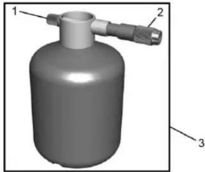
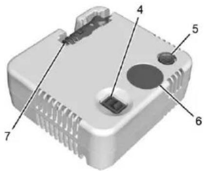
The kit includes:
natural_image
3D rendered image of a cylindrical gas cylinder with two labeled connectors (no text or symbols)- Sealant Canister Inlet Valve
-
Sealant/Air Hose
-
Tire Sealant Canister
text_image
Labeled diagram of a 3D electronic device with numbered parts for identification- On/Off Button
- Pressure Deflation Button
-
Pressure Gauge
-
Power Plug
natural_image
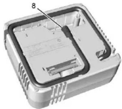
3D cutaway view of an electronic device showing internal components and casing (no text or symbols)- Air Only Hose
Tire Sealant
Read and follow the safe handling instructions on the label adhered to the tire sealant canister (3).
Check the tire sealant expiration date on the tire sealant canister. The tire sealant canister (3) should be replaced before its expiration date. Replacement tire sealant canisters are available at your local dealer.
There is only enough sealant to seal one tire. After usage, the tire sealant canister must be replaced.
Using the Tire Sealant and Compressor Kit to Temporarily Seal and Inflate a Punctured Tire
When using the tire sealant and compressor kit during cold temperatures, warm the kit in a heated environment for five minutes. This will help to inflate the tire faster.
If a tire goes flat, avoid further tire and wheel damage by driving slowly to a level place. Turn on the hazard warning flashers. See Hazard Warning Flashers 8.
See your owner's manual for other important safety warnings.
Do not remove any objects that have penetrated the tire.
- Remove the tire sealant canister (3) and compressor from its storage location. See your owner's manual.
- Remove the air only hose (8) and the power plug (7) from the compressor.
- Place the compressor on the ground near the flat tire.
text_image
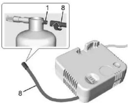
Diagram of a gas washing device with labeled parts and an inset showing a gas outlet tube assembly.-
Remove the cap from the sealant canister inlet valve (1) by turning it counterclockwise. Attach the air only hose (8) to the sealant canister inlet valve (1) by turning it clockwise until tight.
-
Remove the valve stem cap from the flat tire by turning it counterclockwise.
text_image
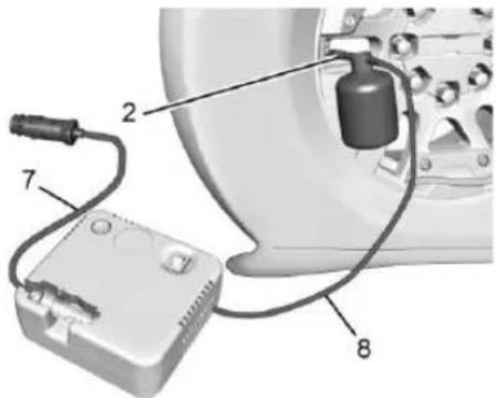
Diagram of an electronic device with labeled components including a battery, cable, and housing-
Attach the sealant/air hose (2) to the tire valve stem by turning it clockwise until tight.
-
Plug the power plug (7) into the accessory power outlet in the vehicle. Unplug all items from other accessory power outlets. See your owner's manual.
If the vehicle has an accessory power outlet, do not use the cigarette lighter.
If the vehicle only has a cigarette lighter, use the cigarette lighter.
Do not pinch the power plug cord in the door or window.
-
Start the vehicle. The vehicle must be running while using the air compressor.
-
Press the on/off button (4) to turn the tire sealant and compressor kit on.
The compressor will inject sealant and air into the tire.
The pressure gauge (6) will initially show a high pressure while the compressor pushes the sealant into the tire. Once the sealant is completely dispersed into the tire, the pressure will quickly drop and start to rise again as the tire inflates with air only.
- Inflate the tire to the recommended inflation pressure using the pressure gauge (6). The recommended inflation pressure can be found on the Tire and Loading Information label. See your owner's manual.
The pressure gauge (6) may read higher than the actual tire pressure while the compressor is on. Turn the compressor off to get an accurate pressure reading. The compressor may be turned on/off until the correct pressure is reached.
Caution
If the recommended pressure cannot be reached after approximately 25 minutes, the vehicle should not be driven farther. The tire is too severely damaged and the tire sealant and compressor kit cannot inflate the tire. Remove the power plug from the accessory power outlet and unscrew the inflating hose from the tire valve. See Roadside Assistance Program 24.
- Press the on/off button (4) to turn the tire sealant and compressor kit off.
The tire is not sealed and will continue to leak air until the vehicle is driven and the sealant is distributed in the tire. Therefore, Steps 12–20 must be done immediately after Step 11.
Be careful while handling the tire sealant and compressor kit as it could be warm after usage. - Unplug the power plug (7) from the accessory power outlet in the vehicle.
-
Turn the sealant/air hose (2) counterclockwise to remove it from the tire valve stem.
-
Replace the tire valve stem cap.
- Turn the air only hose (8) counterclockwise to remove it from the tire sealant canister inlet valve (1).
- Replace the tire sealant canister inlet valve (1) cap.
- Return the air only hose (8) and power plug (7) back to their original storage location.
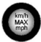
- If the flat tire was able to inflate to the recommended inflation pressure, remove the maximum speed label from the sealant canister and place it in a highly visible location.
Do not exceed the speed on this label until the damaged tire is repaired or replaced. - Return the equipment to its original storage location in the vehicle.
-
Immediately drive the vehicle 8 km (5 mi) to distribute the sealant in the tire.
-
Stop at a safe location and check the tire pressure. Refer to Steps 1–10 under "Using the Tire Sealant and Compressor Kit without Sealant to Inflate a Tire (Not Punctured)."
If the tire pressure has fallen more than 68 kPa (10 psi) below the recommended inflation pressure, stop driving the vehicle. The tire is too severely damaged and the tire sealant cannot seal the tire. See Roadside Assistance Program 24.
If the tire pressure has not dropped more than 68 kPa (10 psi) from the recommended inflation pressure, inflate the tire to the recommended inflation pressure.
- Wipe off any sealant from the wheel, tire, or vehicle.
- Dispose of the used tire sealant canister (3) at a local dealer or in accordance with local state codes and practices.
- Replace it with a new canister available from your dealer.
- After temporarily sealing a tire using the tire sealant and compressor kit, take the vehicle to an authorized dealer within 161 km (100 mi) of driving to have the tire repaired or replaced.
Using the Tire Sealant and Compressor Kit without Sealant to Inflate a Tire (Not Punctured)
The kit includes:

natural_image
3D rendering of a cylindrical gas cylinder with three labeled parts (1, 2, 3), no text or symbols present.- Sealant Canister Inlet Valve
-
Sealant/Air Hose
-
Tire Sealant Canister
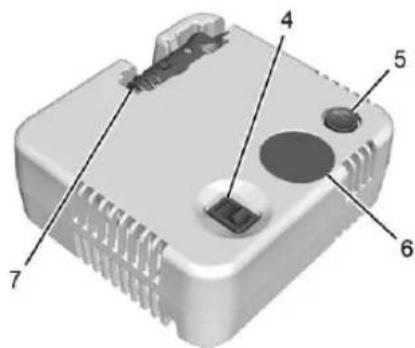
text_image
Diagram of a device component with numbered parts labeled 4, 5, 6, and 7- On/Off Button
- Pressure Deflation Button
-
Pressure Gauge
-
Power Plug
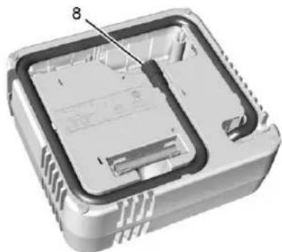
natural_image
3D cutaway view of an electronic device showing internal components and a labeled part (8), no text or symbols present.- Air Only Hose
If a tire goes flat, avoid further tire and wheel damage by driving slowly to a level place. Turn on the hazard warning flashers. See Hazard Warning Flashers 8.
See your owner's manual for other important safety warnings.
- Remove the compressor from its storage location. See your owner's manual.
- Remove the air only hose (8) and the power plug (7) from the compressor.
- Place the compressor on the ground near the flat tire.
Make sure the tire valve stem is positioned close to the ground so the hose will reach it.
-
Remove the valve stem cap from the flat tire by turning it counterclockwise.
-
Attach the air only hose (8) to the tire valve stem by turning it clockwise until tight.
-
Plug the power plug (7) into the accessory power outlet in the vehicle. Unplug all items from other accessory power outlets. See your owner's manual.
If the vehicle has an accessory power outlet, do not use the cigarette lighter.
If the vehicle only has a cigarette lighter, use the cigarette lighter.
Do not pinch the power plug cord in the door or window.
-
Start the vehicle. The vehicle must be running while using the air compressor.
-
Press the on/off button (4) to turn the tire sealant and compressor kit on.
The compressor will inflate the tire with air only.
- Inflate the tire to the recommended inflation pressure using the pressure gauge (6). The recommended inflation
pressure can be found on the Tire and Loading Information label. See your owner's manual.
The pressure gauge (6) may read higher than the actual tire pressure while the compressor is on. Turn the compressor off to get an accurate pressure reading. The compressor may be turned on/off until the correct pressure is reached.
Caution
If the recommended pressure cannot be reached after approximately 25 minutes, the vehicle should not be driven farther. The tire is too severely damaged and the tire sealant and compressor kit cannot inflate the tire. Remove the power plug from the accessory power outlet and unscrew the inflating hose from the tire valve. See Roadside Assistance Program 24.
-
Press the on/off button (4) to turn the tire sealant and compressor kit off. Be careful while handling the compressor as it could be warm after usage.
-
Unplug the power plug (7) from the accessory power outlet in the vehicle.
-
Turn the air only hose (8) counterclockwise to remove it from the tire valve stem.
- Replace the tire valve stem cap.
- Return the air only hose (8) and power plug (7) back to their original storage location.
- Return the equipment to its original storage location in the vehicle.
Accessory adapters that can be used to inflate an air mattress or a ball, etc., are located on the bottom of the compressor kit
Jump Starting - North America
For more information about the vehicle battery, see your owner's manual.
If the battery has run down, try to use another vehicle and some jumper cables to start your vehicle. Be sure to use the following steps to do it safely.

Warning
WARNING: Battery posts, terminals and related accessories can expose you to chemicals including lead and lead compounds, which are known to the State
(Continued)
Warning (Continued)
of California to cause cancer and birth defects or other reproductive harm. Wash hands after handling. For more information go to www.P65Warnings.ca.gov.
See California Proposition 65 Warning ➔ 1.

Warning
Batteries can hurt you. They can be dangerous because:
• They contain acid that can burn you.
• They contain gas that can explode or ignite.
• They contain enough electricity to burn you.
Use eye protection when handling the battery. If you do not follow these steps exactly, some or all of these things can hurt you.

Warning
Charging the 12-volt battery and the high voltage battery at the same time may result in overheating or failure. Do not attempt to charge the 12-volt battery and the high voltage battery at the same time. If jumpstarting fails, see your dealer for service.
Caution
The vehicle is equipped with an AGM/VRLA 12-volt battery, which can be damaged by using the incorrect type of trickle charger. An AGM/VRLA-compatible charger must be used, with the appropriate setting selected. Follow the trickle charger manufacturer instructions.
Caution
Ignoring these steps could result in costly damage to the vehicle that would not be covered by the vehicle warranty. Trying to start the vehicle by pushing or pulling it will not work, and it could damage the vehicle.
Caution
If the jumper cables are connected or removed in the wrong order, electrical shorting may occur and damage the vehicle. The repairs would not be covered by the vehicle warranty. Always connect and remove the jumper cables in the correct order, making sure that the cables do not touch each other or other metal.
text_image
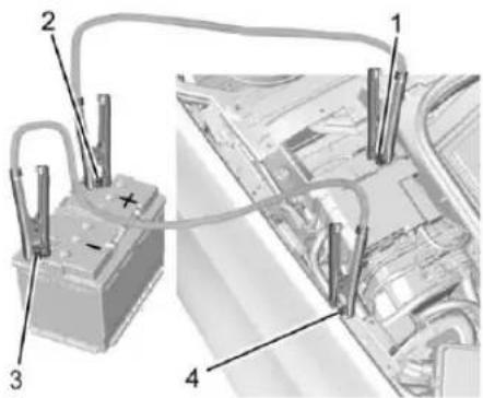
Technical diagram showing a battery connected to four labeled parts of an electrical or mechanical system, with annotations 1, 2, and 3.Connection Points and Sequence
- Discharged Battery Positive (+) Terminal
-
Good Battery Positive (+) Terminal
-
Good Battery Negative (−) Terminal
- Discharged Battery Negative (−) Grounding Point
The discharged battery positive (+) terminal and the discharged battery negative (−) grounding point are on the passenger side of the vehicle.
The good battery negative (−) terminal and the good battery positive (+) terminal are on the battery of the vehicle providing the jump start.
The discharged battery positive (+) terminal and the discharged battery negative (−) grounding point are under a cover. Remove the cover to expose the terminal.
Caution
If the other vehicle does not have a 12-volt system with a negative ground, both vehicles can be damaged. Only use a vehicle that has a 12-volt system with a negative ground for jump starting.
- Check the other vehicle. It must have a 12-volt battery with a negative ground system.
Caution
If the vehicles touch each other while jump starting, a ground connection may occur that disables your vehicle and/or damages the electrical systems of one or both vehicles.
- Get the vehicles close enough so the jumper cables can reach, but make sure the vehicles are not touching each other.
- To avoid the possibility of the vehicles rolling, set the parking brake firmly on both vehicles involved in the jump start procedure. Put the vehicles into P (Park). If the other vehicle has a manual transmission, put the vehicle in N (Neutral) before setting the parking brakes.
Caution
If any accessories are left on or plugged in during the jump starting procedure, they could be damaged. The repairs would not be covered by the vehicle warranty. Whenever possible, turn off or unplug all accessories on either vehicle when jump starting.
- Turn off both vehicles. Unplug unnecessary accessories plugged into the cigarette lighter or the accessory power outlet. Turn off the radio and all lights that are not needed.
- Open the hood. See Hood 2.
natural_image
3D rendering of a car interior showing a dark panel and structural details (no text or symbols visible)-
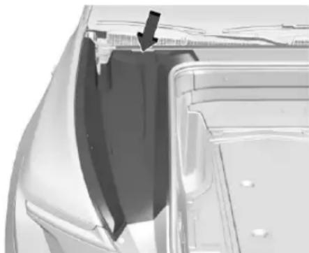
The battery positive (+) terminal and negative (−) grounding point are under a cover and side extension/shield in the underhood compartment. Remove the shield, starting at the top. Once the shield clips disengage, the tabs along the bottom can disengage to remove the left side access cover.
-
Remove the covers of the positive and negative terminals.
- Locate the battery positive (+) terminal and negative (−) grounding point.

Warning
Always inspect jumper cables prior to use. Jumper cables with loose or missing insulation could shock you or cause vehicle damage. Do not use jumper cables that appear damaged.
- Check that the jumper cables do not have loose or missing insulation.
- Connect one end of the red positive (+) cable to the discharged battery positive (+) terminal. Do not let the other end touch metal.
- Connect the other end of the red positive (+) cable to the good battery positive (+) terminal.
-
Connect one end of the black negative (-) cable to the good battery negative (-) terminal. Do not let the other end touch anything until the next step.
-
Connect the other end of the negative (−) cable to the discharged battery negative (−) grounding point.
- Now start the vehicle with the good battery and keep the vehicle running for a while.
- Try to start the vehicle that had the dead battery. If it will not start after a few tries, it probably needs service.
Jumper Cable Removal
To remove the jumper cables, reverse Steps 10–13 in exact order.
After starting the disabled vehicle and removing the jumper cables, allow it to idle for several minutes.
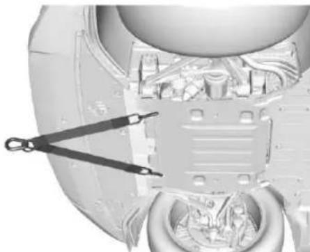
Transporting a Disabled Vehicle
Caution
Incorrectly transporting a disabled vehicle may cause damage to the vehicle. Use proper tire straps to secure the vehicle to the flatbed tow truck. Do not strap or hook to any frame, underbody, or suspension component not specified below. Do not
(Continued)
Caution (Continued)
move vehicles with drive axle tires on the ground. Damage is not covered by the vehicle warranty.
Caution
The vehicle may be equipped with an Electric Parking Brake (EPB) and/or an electronic shifter. In the event of a loss of 12-volt battery power, the EPB cannot be released, and the vehicle cannot be shifted to N (Neutral). Tire skates or dollies must be used under the non-rolling tires to prevent damage while loading/unloading the vehicle. Dragging the vehicle will cause damage not covered by the vehicle warranty.
Contact a professional towing service if the disabled vehicle must be transported. GM recommends a flatbed tow truck to transport a disabled vehicle. Use ramps to help reduce approach angles, if necessary.
The vehicle must be in N (Neutral) and the electric parking brake must be released when loading the vehicle onto a flatbed tow truck.
- If the vehicle will not start but still has 12-volt battery power, buckle the driver seat belt then press and hold the brake pedal for 60 seconds and shift into N (Neutral).
- If the vehicle is equipped with car wash mode and has 12-volt battery power, see "Car Wash Mode" in your owner's manual to place the vehicle in N (Neutral).
- If the 12-volt battery is dead and/or the vehicle will not start, the vehicle will not move. Try to jump start the vehicle. See Jump Starting - North America ⇌ 20 and if the jump start is successful, retry the "Car Wash Mode" procedure.
- If jump starting is unsuccessful, the vehicle will not move. Tire skates or dollies must be used under the non-rolling tires to prevent vehicle damage.
Front Attachment Points
natural_image
Cross-sectional view of a spacecraft's internal components, showing structural elements and a tool interacting with them (no text or symbols visible)The vehicle is equipped with specific attachment points to be used to pull the vehicle onto a flatbed car carrier from a flat road surface. Do not use these attachment points to pull the vehicle from snow, mud, sand, or a ditch.
Customer Assistance for Text Telephone (TTY) Users
To assist customers who are deaf, hard of hearing, or speech-impaired and/or who use Text Telephones (TTYs), please dial the national 711 relay service and contact 1-800-833-2438. TTY users in Canada can dial 1-800-263-3830.
Roadside Assistance Program
U.S.: 1-844-515-1420.
Canada: 1-844-637-1757.
Text Telephone (TTY) Users (U.S.
Only): 1-888-889-2438.
Reporting Safety Defects to the United States Government
If you believe that your vehicle has a defect which could cause a crash or could cause injury or death, you should immediately inform the National Highway Traffic Safety Administration (NHTSA) in addition to notifying General Motors.
If NHTSA receives similar complaints, it may open an investigation, and if it finds that a safety defect exists in a group of vehicles, it may order a recall and remedy campaign. However, NHTSA cannot become involved in individual problems between you, your dealer, or General Motors.
To contact NHTSA, you may call the Vehicle Safety Hotline toll-free at 1-888-327-4236 (TTY: 1-877-561-7439); go to https://www.safercar.gov; or write to: Administrator, NHTSA 1200 New Jersey Avenue, S.E., Washington, D.C., 20590 You can also obtain other information about motor vehicle safety from https://www.safercar.gov.
Reporting Safety Defects to the Canadian Government
If you live in Canada, and you believe that the vehicle has a safety defect, notify Transport Canada immediately, and notify General Motors of Canada Company. Call Transport Canada at 1-800-333-0510; go to: www.tc.gc.ca/recalls (English) www.tc.gc.ca/rappels (French) or write to: Transport Canada Motor Vehicle Safety Directorate Defect Investigations and Recalls Division
80 Noel Street Gatineau, QC J8Z 0A1
Reporting Safety Defects to General Motors
In addition to notifying National Highway Traffic Safety Administration (NHTSA) (or Transport Canada) in a situation like this, notify General Motors. In the U.S., call 1-800-458-8006, or write: Cadillac Customer Assistance Center Cadillac Motor Car Division P.O. Box 33169 Detroit, MI 48232-5169 In Canada, call 1-888-446-2000, or write: Canadian Cadillac Customer Care Centre General Motors of Canada Company 500 Wentworth Street W Oshawa, ON L1J 0C5 In Mexico, call 800-466-0805 or 800-212-2345. In other Central America and Caribbean Countries, call 52-555-901-2369.

ESCALADE IQ/ESCALADE IQL RENSEIGNEMENTS DE RÉFÉRENCE SUR LE VÉHICULE


85625870 A
2026

FSC
MIX
Essuie-glace/Lave-glace 8
natural_image
Close-up of a white car door handle with a black arrow pointing to the side (no text or symbols)natural_image
Interior view of a car showing the dashboard and air vent (no text or symbols visible)natural_image
Front view of a modern electric car with a black upward arrow indicating front grille (no text or symbols)natural_image
Close-up of a white remote control key with function buttons and a circular dial (no text or symbols visible)natural_image
3D rendering of a car's front bumper and seat, showing dimensional annotations (no text or symbols)natural_image
Interior view of a car showing the roof and side panels with a black arrow pointing to a circular component (no text or symbols visible)text_image
Close-up of a car door panel with a digital display showing a person icon and Chinese character '人' (person)Essuie-glace/Lave-glace
natural_image
Exterior view of a modern electric vehicle charging plug (no text or symbols visible)natural_image
Close-up of a car door panel with two directional arrows indicating movement (no text or symbols)natural_image
Close-up of a white plastic door with a black arrow pointing to a button (no text or symbols visible)natural_image
Close-up of a car door panel with two black arrows pointing to the side (no text or symbols visible)natural_image
Close-up of a car interior showing a passenger inside a vehicle (no visible text or symbols)natural_image
Close-up of a white plastic door with a black arrow pointing to a circular button (no text or symbols visible)natural_image
Side view of a car's front wheel and side panel, showing a black arrow pointing to the wheel (no text or symbols visible)natural_image
Close-up of a car wheel rim with a black arrow pointing to the edge (no text or symbols visible)natural_image
Top-down view of a car's front bumper with visible structural components (no text or symbols)natural_image
3D rendering of a cylindrical gas cylinder with two labeled ports (no text or symbols on the object itself)text_image
Diagram of a device component with numbered parts labeled 4 through 7natural_image
3D rendering of an electronic device casing with internal components and labeled part '8' (no text or symbols beyond label)- Flexible d'air
text_image
Diagram of a gas delivery device with labeled parts, showing internal components and a magnified view of the bottle's internal structure.text_image
Diagram of an electronic device with labeled components including a battery, switch, and gas cylinder connectionnatural_image
3D rendering of a cylindrical gas cylinder with two labeled ports (no text or symbols on the object itself)text_image
Labeled diagram of a device component with numbered parts 4, 5, 6, and 7natural_image
3D cutaway view of an electronic device showing internal components and casing (no text or symbols)- Flexible d'air
text_image
Diagram showing a battery connected to four labeled parts, likely illustrating electrical or mechanical connections.natural_image
Close-up of a car's front panel showing the side door and seat, with a black arrow pointing to the interior (no text or symbols visible)natural_image
Close-up of a mechanical assembly with internal components and a tool, no visible text or symbolsAdministrator, NHTSA
1200 New Jersey Avenue, S.E., Washington, D. C., 20590
500 Wentworth Street W
Oshawa, ON (activé) L1J 0C5