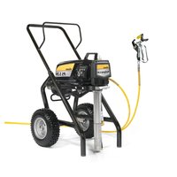
ProSpray 3.39 - Paint gun WAGNER - Free user manual and instructions
Find the device manual for free ProSpray 3.39 WAGNER in PDF.


| Product type | Airless Paint Sprayer |
| Brand | Wagner |
| Model | ProSpray 3.39 |
| Maximum operating pressure | 221 bar (22.1 MPa) |
| Flow rate (at 120 bar with water) | 4.5 l/min |
| Maximum nozzle orifice | 0.039 inches (0.99 mm) |
| Maximum product viscosity | 30,000 mPa·s |
| Maximum product temperature | 43 °C |
| Power consumption | 2185 Watts |
| Voltage / Frequency | 220-240 V AC, 50/60 Hz |
| Maximum current | 9.5 A |
| Weight | 50 kg |
| Dimensions (L x W x H) | 632 x 568 x 743 mm |
| High-pressure hose | DN 6 mm, 15 m, connection M16x1.5 |
| Maximum sound level | 80 dB(A) |
| Control system | Digital Electronic Spray Control (DESC) |
| Safety | Trigger lock lever, nozzle guard |
| Maintenance | Daily cleaning of the inlet grid, pressure relief before maintenance |
| Spare parts | Seal kits, filters, nozzles, valves available |
Frequently Asked Questions - ProSpray 3.39 WAGNER
User questions about ProSpray 3.39 WAGNER
0 question about this device. Answer the ones you know or ask your own.
Ask a new question about this device
Download the instructions for your Paint gun in PDF format for free! Find your manual ProSpray 3.39 - WAGNER and take your electronic device back in hand. On this page are published all the documents necessary for the use of your device. ProSpray 3.39 by WAGNER.
USER MANUAL ProSpray 3.39 WAGNER
natural_image
Line drawing of a portable power tool with wheels and handle (no text or symbols)PROSPRAY 3.39
BETRIEBSANLEITUNG • OWNER'S MANUAL MODE D'EMPLOI • ISTRUZIONE PER L'USO
MODEL:
0558008
0558040

Warnung!

GeFAHR: HocHdRucKScHLAucH
GeFAHR: exPLoSloNS- uNd BRANdGeFAHR
3.6 TRANSPORT
3.7 TRANSPORT IM FAHRZEUG
8.4 ReINIGuNG deR AIRLeSS-SPRITzPISToLe

11.2 eIN- uNd AuSLASSVeNTIL
natural_image
Illustration of a mechanical device with no visible text or symbolsnatural_image
Line drawing of a temperature sensor device with coiled tubing and connector (no text or symbols on the device itself)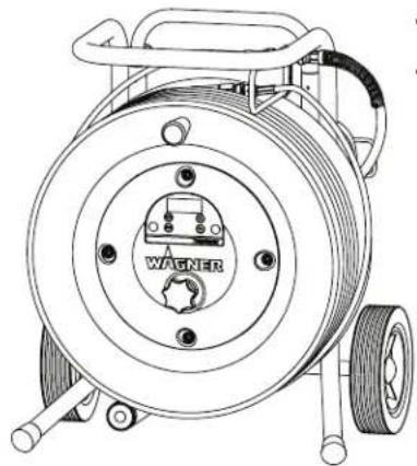
natural_image
Technical line drawing of a mechanical pump or reel assembly with no visible text or symbolsTempSpray H 226 TempSpray H 326
12.6 PUMP-RUNNER
(Best. Nr. 2306987)
natural_image
Line drawing of a mechanical component with threaded base and central clip (no text or symbols)
Attention: Danger of injury by injection! Airless units develop extremely high spraying pressures.


Never put your fingers, hands or any other parts of the body into the spray jet!
Never point the spray gun at yourself, other persons or animals. Never use the spray gun without safety guard.
Do not treat a spraying injury as a harmless cut. In case of injury to the skin through coating materials or solvents, consult a doctor immediately for quick and expert treatment. Inform the doctor about the coating material or solvent used.

The operating instructions state that the following points must always be observed before starting up:
- Faulty units must not be used.
- Secure Wagner spray gun using the trigger lock on the trigger.
- Ensure that the unit is properly earthed.
- Check allowable operating pressure of high-pressure hose and spray gun.
- Check all connections for leaks.

The instructions regarding regular cleaning and maintenance of the unit must be strictly observed.
Before any work is done on the unit or for every break in work the following rules must be observed:
- Release the pressure from spray gun and hose.
- Secure the Wagner spray gun using the trigger lock on the trigger.
- Switch off unit.
Be safety conscious!
1 SAFeTy ReGuLATIoNS FoR AIRLeSS SPRAyING 36
1.1 Explanation of symbols used 36
1.2 Electric safety 40
1.3 Electrostatic charging
(formation of sparks or flames) ____ 40
2 GeNeRAL Vl eW oF APPLlcATIoN 41
2.1 Application 41
2.2 Coating materials 41
3 deScRIPTIoN oF uNIT 42
3.1 Airless process 42
3.2 Functioning of the unit 42
3.3 Technical data 42
3.4 Legend for explanatory diagram PS 3.39 ____ 43
3.5 Explanatory diagram PS 3.39 43
3.6 Transportation 44
3.7 Transportation in vehicle 44
3.8 Painting material setup 44
3.9 Textured material setup 44
4 STARTING oPeRATIoN 45
4.1 High-pressure hose, spray gun and separating oil _ 45
4.2 Control panel indicators 46
4.3 Pressure control knob settings 46
4.4 Connection to the mains network 47
4.5 Cleaning preserving agent when starting-up of operation initially ____ 47
4.6 Taking the unit into operation with coating material 47
4.7 Digital Electronic Spray Control (DESC) 48
5 SPRAyING TecHNIque 50
6 HANdLING THE HIGH-PReSSuRe HoSe \_\_\_\_ 51
7 INTeRRuPTIoN oF WoWK 51
8 cLeANING THE uNIT (SHuTTING doWN) \_ 52
8.1 Cleaning unit from outside 52
8.2 Cleaning the inlet screen 52
8.3 Cleaning the high-pressure filter 53
8.4 Cleaning Airless spray gun 53
9 Remedy IN cASe of FAuLTS 54
10 SeRVlcING 55
10.1 General servicing ____ 55
10.2 High-pressure hose 55
11 RePAIRS AT THE uNIT 55
11.1 Relief valve 55
11.2 Inlet and outlet valve 56
11.3 Packings 57
11.4 PS 3.39 connection diagram 59
11.5 Digital Electronic Spray Control (DESC)
Error Messages ____ 60
12 APPeNdIx 61
12.1 Selection of tip 61
12.2 Servicing and cleaning of Airless hard-metal tips ____61
12.3 Spray gun accessories 61
12.4 Airless tip table 62/63
12.5 TempSpray 64
12.6 Pump-Runner 65
AcceSSoRleS FoR PRoSPRAy 3.39 \_\_\_\_ 130/131
Spare parts list for main assembly 132/133
Spare parts list for the fluid section 134/135
Spare parts list for drive assembly 136/137
Spare parts list of filter assembly 138
Spare parts list of upright cart assembly 139
ImPoRTANT NoTeS oN PROducT LIABILITY \_141
3+2 yeARS GuARANTee FoR PRoFeSSIoNAL
FINISHING 141
SALeS AND SeRVIce comPANleS 147/148
1 SAFeTy ReGuLATIoNS FoR AIRLeSS SPRAyING
1.1 exPLANATIoN oF SymBoLS uSed
This manual contains information that must be read and understood before using the equipment. When you come to an area that has one of the following symbols, pay particular attention and make certain to heed the safeguard.

→ This symbol indicates a potential hazard that may cause serious injury or loss of life. Important safety information will follow.

→ This symbol indicates a potential hazard to you or to the equipment. Important information that tells how to prevent damage to the equipment or how to avoid causes of minor injuries will follow.

→ Danger of skin injection

→ Danger of fire from solvent and paint fumes

Danger of explosion from solvent, paint fumes and incompatible materials

→ Danger of injury from inhalation of harmful vapors

Notes give important information → which should be given special attention.

HAzARd: INJecTloN INJuRy
Attention: Danger of injury by injection! A high pressure stream produced by this equipment can pierce the skin and underlying tissues, leading to serious injury and possible amputation.
Do not treat a spraying injury as a harmless cut. In case of injury to the skin through coating materials or solvents, consult a doctor immediately for quick and expert treatment. Inform the doctor about the coating material or solvent used.
PReVeNTIoN:
• NEVER aim the gun at any part of the body.
- NEVER allow any part of the body to touch the fluid stream. DO NOT allow body to touch a leak in the fluid hose.
- NEVER put your hand in front of the gun. Gloves will not provide protection against an injection injury.
- ALWAYS lock the gun trigger, shut the fluid pump off and release all pressure before servicing, cleaning the tip guard, changing tips, or leaving unattended. Pressure will not be released by turning off the engine. The PRIME/SPRAY valve or pressure bleed valve must be turned to their appropriate positions to relieve system pressure.
- ALWAYS keep tip guard in place while spraying. The tip guard provides some protection but is mainly a warning device.
- ALWAYS remove the spray tip before flushing or cleaning the system.
- NEVER use a spray gun without a working trigger lock and trigger guard in place.
- All accessories must be rated at or above the maximum operating pressure range of the sprayer. This includes spray tips, guns, extensions, and hose.

HAzARd: HIGH PReSSuRe HoSe
The paint hose can develop leaks from wear, kinking and abuse. A leak can inject material into the skin. Inspect the hose before each use.
PReVeNTIoN:
- Avoid sharp bending or kinking of the high-pressure hose. The smallest bending radius amounts to about 20 cm.
- Do not drive over the high-pressure hose. Protect against sharp objects and edges.
- Replace any damaged high-pressure hose immediately.
- Never repair defective high-pressure hoses yourself!
- Electrostatic charging of spray guns and the high-pressure hose is discharged through the high-pressure hose. For this reason the electric resistance between the connections of the high-pressure hose must be equal to or lower than 1MΩ.
- For reasons of function, safety and durability use only original Wagner high-pressure hoses.
- Before each use, check all hoses for cuts, leaks, abrasion or bulging of cover. Check for damage or movement of couplings. Immediately replace the hose if any of these conditions exist. Never repair a paint hose. Replace it with another earthed high-pressure hose.
- Make sure power cord, air hose and spray hoses are routed in such a manner to minimize slip, trip and fall hazard.

HAzARd: exPLoSloN oR FIRe
Flammable vapors, such as solvent and paint vapors, in work area can ignite or explode.
PReVeNTIoN:
- Do not use materials with a flashpoint below 38^ C ( 100^ F). Flashpoint is the temperature at which a fluid can produce enough vapors to ignite.
- Do not use the unit in work places which are covered by the explosion protection regulations.
- Provide extensive exhaust and fresh air introduction to keep the air within the spray area free from accumulation of flammable vapors.
- Avoid all ignition sources such as static electricity sparks, electrical appliances, flames, pilot lights, hot objects, and sparks from connecting and disconnecting power cords or working light switches.
• Do not smoke in spray area. - Place sprayer sufficient distance from the spray object in a well ventilated area (add more hose if necessary). Flammable vapors are often heavier than air. Floor area must be extremely well ventilated. The pump contains arcing parts that emit sparks and can ignite vapors.
- The equipment and objects in and around the spray area must be properly grounded to prevent static sparks.
- Use only conductive or earthed high pressure fluid hose. Gun must be earthed through hose connections.
- Power cord must be connected to a grounded circuit (electric units only).
- Always flush unit into separate metal container, at low pump pressure, with spray tip removed. Hold gun firmly against side of
container to ground container and prevent static sparks.
- Follow material and solvent manufacturer's warnings and instructions. Be familiar with the coating material's MSDS sheet and technical information to ensure safe use.
- Use lowest possible pressure to flush equipment.
- When cleaning the unit with solvents, the solvent should never be sprayed or pumped back into a container with a small opening (bunghole). An explosive gas/air mixture can arise. The container must be earthed.
- Do not use a paint or solvent containing halogenated hydrocarbons. Such as chlorine, bleach, mildewcide, methylene chloride and trichloroethane. They are not compatible with aluminum. Contact the coating supplier about compatibility of material with aluminum.

HAzARd: HAzARdouS VAPoRS
Paints, solvents, and other materials can be harmful if inhaled or come in contact with body. Vapors can cause severe nausea, fainting, or poisoning.
PReVeNTIoN:
- Wear respiratory protection when spraying. Read all instructions supplied with the mask to be sure it will provide the necessary protection.
- All local regulations regarding protection against hazardous vapors must be observed.
- Wear protective eyewear.
- Protective clothing, gloves and possibly skin protection cream are necessary for the protection of the skin. Observe the regulations of the manufacturer concerning coating materials, solvents and cleaning agents in preparation, processing and cleaning units.

HAzARd: GeNeRAL
This product can cause severe injury or property damage.
PReVeNTIoN:
- Follow all appropriate local, state, and national codes governing ventilation, fire prevention, and operation.
- Pulling the trigger causes a recoil force to the hand that is holding the spray gun. The recoil force of the spray gun is particularly powerful when the tip has been removed and a high pressure has been set on the airless pump. When cleaning without a spray tip, set the pressure control knob to the lowest pressure.
- Use only manufacturer authorized parts. User assumes all risks and liabilities when using parts that do not meet the minimum specifications and safety devices of the pump manufacturer.
- ALWAYS follow the material manufacturer's instructions for safe handling of paint and solvents.
- Clean up all material and solvent spills immediately to prevent slip hazard.
- Wear ear protection. This unit can produce noise levels above 85 dB(A).
- Never leave this equipment unattended. Keep away from children or anyone not familiar with the operation of airless equipment.
• Device weighs in excess of 36 kg. Three-person lift is required.
• Do not spray on windy days. - The device and all related liquids (i.e. hydraulic oil) must be disposed of in an environmentally friendly way.
1.2 eLecTRIc SAFeTy
Electric models must be earthed. In the event of an electrical short circuit, earthing reduces the risk of electric shock by providing an escape wire for the electric current. This product is equipped with a cord having an earthing wire with an appropriate earthing plug. Connection to the mains only through a special feed point, e.g. through an error protection installation with INF < 30 mA.

DANGER — Work or repairs at the electrical equipment may only be carried out by a skilled electrician. No liability is assumed for incorrect installation. Switch the unit off. Before all repair work, unplug the power plug from the outlet.
Danger of short-circuits caused by water ingressing into the electrical equipment. Never spray down the unit with high-pressure or high-pressure steam cleaners.
WoRK oR RePAIRS AT THE eLecTRIcAL equIPmeNT:
These may only be carried out by a skilled electrician. No liability is assumed for incorrect installation.
1.3 eLecTRoSTATIC cHARGING (FoRmATIoN of SPARKS or FLAmeS)

Electrostatic charging of the unit may occur during spraying due to the flow speed of the coating material. These can cause sparks and flames upon discharge. The unit must therefore always be earthed via the electrical system. The unit must be connected to an appropriately-grounded safety outlet.
An electrostatic charging of spray guns and the high-pressure hose is discharged through the high-pressure hose. For this reason the electric resistance between the connections of the high-pressure hose must be equal to or lower than 1 MΩ.
2 GENERAL VIEW OF APPLICATION
2.1 APPLICATION

| Materials | Object Size | Model | ||||||
| PS 3.21 | PS 3.23 | PS 3.25 | PS 3.29 | PS 3.31 | PS 3.34 | PS 3.39 | ||
| Release agents, oils, undercoats, primers, fillers, synthetic resin-based paints, acrylic paints recommended nozzle size: FineFinish 0.008" - 0.014" | up to 200 m2 | |||||||
| 200 m2 - 800 m2 | ||||||||
| more than 800 m2 | ||||||||
| Emulsion paints, latex paints recommended nozzle size: 0.017" - 0.027" | up to 200 m2 | |||||||
| 200 m2 - 800 m2 | ||||||||
| more than 800 m2 | ||||||||
| Anti-corrosive agents, flame retardants, fabric adhesive recommended nozzle size: 0.021" - 0.031" | up to 200 m2 | |||||||
| 200 m2 - 800 m2 | ||||||||
| more than 800 m2 | ||||||||
| Airless-scrapers recommended nozzle size: 0.027" - 0.039" | up to 200 m2 | |||||||
| 200 m2 - 800 m2 | ||||||||
| more than 800 m2 | ||||||||
2.2 COATING MATERIALS
PROCESSIBLE COATING MATERIALS

Pay attention to the Airless quality of the coating materials to be processed.
Dilutable lacquers and paints or those containing solvents, two-component coating materials, dispersions, latex paints, release agents, oils, undercoats, primers, and fillers.
No other materials should be used for spraying without Wagner's approval.
FILTERING
Despite suction filter and insertion filter in the spray gun, filtering of the coating material is generally advisable.
Stir coating material before commencement of work.
Attention: Make sure, when stirring up with motor-driven agitators that no air bubbles are stirred in. Air bubbles disturb when spraying and can, in fact, lead to interruption of operation.
VISCOSITY
With this unit it is possible to process highly viscous coating materials of up to around 30.000 MPa·s.
If highly viscous coating materials cannot be taken in by suction, they must be diluted in accordance with the manufacturer's instructions.
TWO-COMPONENT COATING MATERIAL
The appropriate processing time must be adhered to exactly. Within this time rinse through and clean the unit meticulously with the appropriate cleaning materials.
COATING MATERIALS WITH SHARP-EDGED ADDITIONAL MATERIALS
These have a strong wear and tear effect on valves, high-pressure hose, spray gun and tip. The durability of these parts cane be reduced appreciably through this.
3 DESCRIPTION OF UNIT
3.1 AIRLESS PROCESS
The main areas of application are thick layers of highly viscous coating material for large areas and a high consumption of material.
A piston pump takes in the coating material by suction and conveys it to the tip. Pressed through the tip at a pressure of up to a maximum of 221 bar (22.1 MPa), the coating material is atomised. This high pressure has the effect of micro fine atomisation of the coating material.
As no air is used in this process, it is described as an AIRLESS process.
This method of spraying has the advantages of finest atomisation, cloudless operation and a smooth, bubble-free surface. As well as these, the advantages of the speed of work and convenience must be mentioned.
3.2 FUNCTIONING OF THE UNIT
In the following there is a short description of the technical construction for better understanding of the function.
Wagner PS 3.39 units are electrically driven high-pressure spraying units.
A gear unit transfers the driving force to a crankshaft. The crankshaft moves the pistons of the material feed pump up and down.
The inlet valve is opened automatically by the upwards movement of the piston. The outlet valve is opened when the piston moves downward.
The coating material flows under high pressure through the high-pressure hose to the spray gun. When the coating material exits from the tip it atomizes.
The pressure control knob controls the volume and the operating pressure of the coating material.
3.3 TECHNICAL DATA
| Voltage | |
| 220~240 VAC, 50/60 Hz | |
| Max. current consumption | |
| 9.5 A | |
| Power Cord | |
| 3 x 1.5 mm2 - 6 m | |
| Acceptance capacity | |
| 2185 Watt | |
| Max. operating pressure | |
| 221 bar (22.1 MPa) | |
| Volume flow at 12 MPa (120 bar) with water | |
| 5.0 l/min | |
| Max tip size | |
| 0.039 inch - 0.99 mm | |
| Max. temperature of the coating material | |
| 43°C | |
| Max viscosity | |
| 30.000 MPa·s | |
| Weight | |
| 50 kg | |
| Special high-pressure hose | |
| DN 6 mm, 15 m, connection thread M 16 x 1.5 | |
| Dimensions (L X W X H) | |
| 632 x 568 x 743 mm | |
| Altitude | |
| This equipment | will operate correctly up to 2000 m above mean sea level |
| Vibration | |
| Spray gun does not exceed 2.5m/s2 | |
| Max sound pressure level | |
| 80 dB* | |
* Place of measurement: 1 m distance from unit and 1.60m above floor, 12 MPa (120 bar) operating pressure, reverberant floor
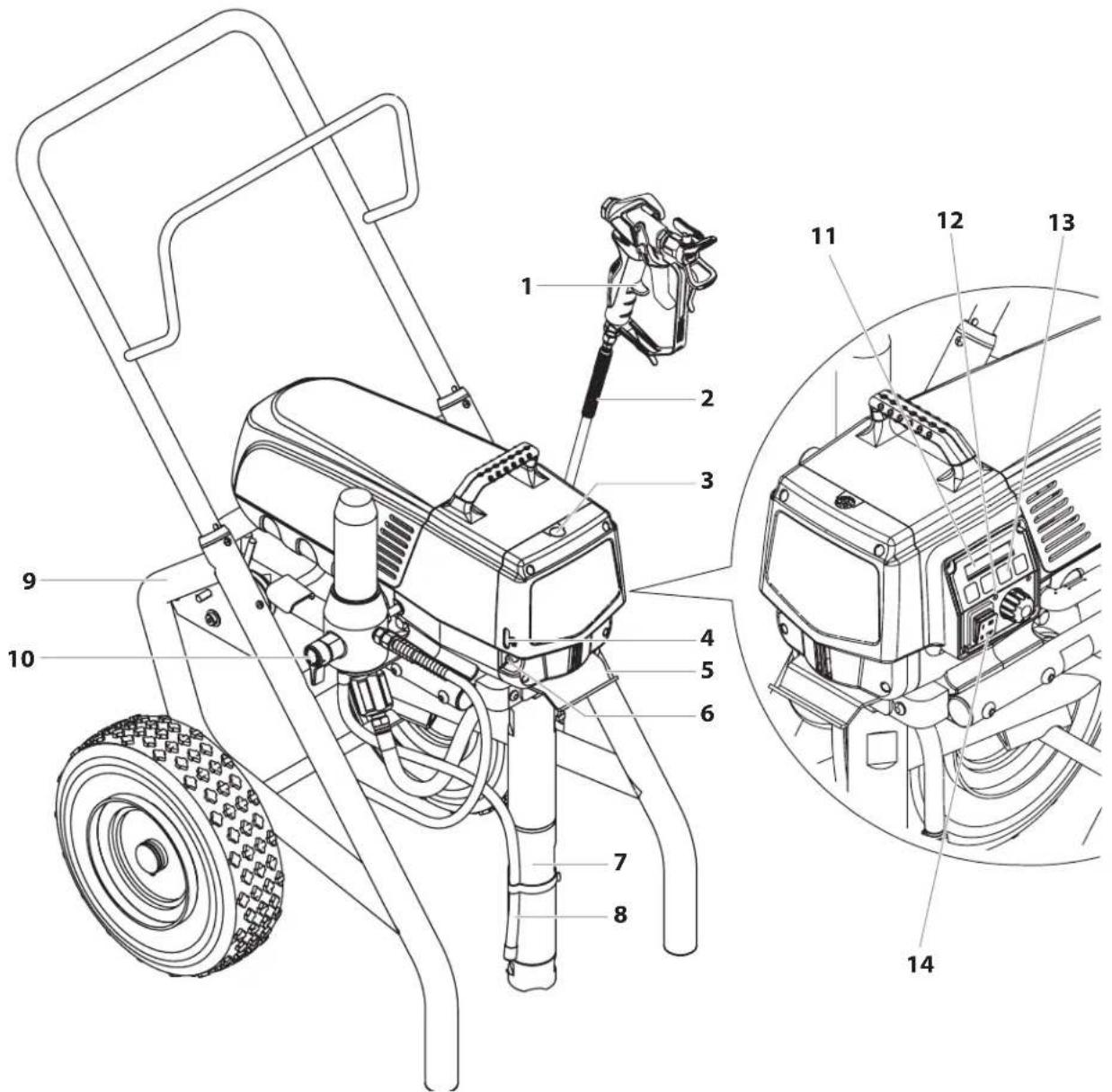
3.4 LeGeNd FoR exPLANAToRy dIAGRAM PRoSPRAy 3.39
-
Spray gun
-
Pail hook
-
High-pressure hose
-
Oil button
-
Oil cup for EasyGlide (EasyGlide prevents increased wear of the packings)
-
Suction tube
-
Oil level gauge
-
Return hose
-
Cart
-
Relief valve
Lever position vertical - PRIME ( circulation) Lever position horizontal - SPRAY ( ≥slant )
-
Digital Electronic Spray Control (DESC)
-
Control panel indicators
-
Pressure control knob
-
ON/OFF switch
3.5 exPLANAToRy dIAGRAM PS 3.39
①
3.6 TRANSPORTATION
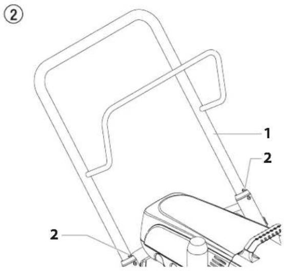
Pushing or pulling the unit
Pull out the handle (Fig. 2, Item 1) until it will come no further. Insert the handle – push the buttons (2) on the spars, and then push in the handle.
3.7 TRANSPORTATION IN VEHICLE
Secure the unit with a suitable fastening.
3.8 PAINT MATERIAL SETUP
| i | This sprayer comes with a filter assembly installed. If you plan to spray with untextured painting materials, leave the filter installed. |
3.9 TEXTURED MATERIAL SETUP
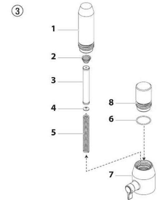
| i | This sprayer comes with a filter plug that should be put in place of the filter whenever spraying textured materials. Follow these steps to remove the filter and install the plug. |
- Loosen and remove the filter housing (1) by hand.
- Remove the adapter spring (2), filter (3), bearing ring (4) and spring (5) from the housing (7).
- Make sure the O-ring (6) is still in place. Thread the filter plug (8) into the housing until secure.
| The filter plug should be hand-tightened, but make sure it is seated fully into the filter housing. |
| If using this sprayer with textured materials, it is important that the filter inside of the spray gun be removed. See section 8.3. | |
| If the sprayer will be used for spraying textured products, removal of the inlet screen in the foot valve may be necessary. This will allow proper priming and flow of the textured product. See section 8.2. |
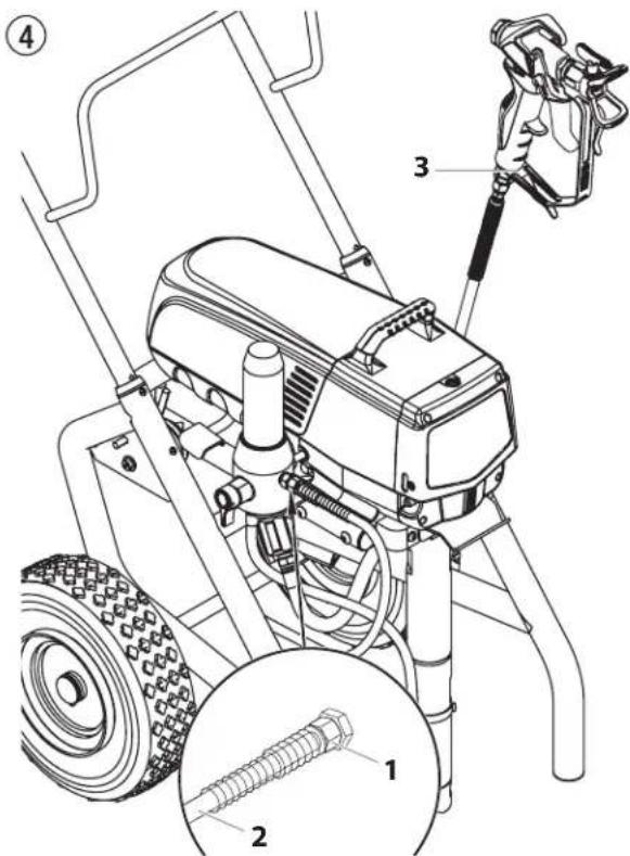
- Screw the high-pressure hose (2) to the coating material outlet (Fig. 4, Item 1).
- Screw the spray gun (3) with the selected tip onto the high-pressure hose.
- Tighten the union nuts at the high-pressure hoses firmly so that coating material does not leak.
-
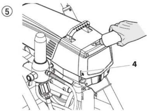
Remove the oil cup cap with a straight-slot screwdriver.
-
Fill the oil cup with EasyGlide (Fig. 5) until the oil gauge (4) is showing that it is full.

EasyGlide prevents increased wear and tear to the packings.
-
Replace oil cup cap.
-
Press oil button 2-5 times to prime the oiler. Press once for every eight hours of usage to lubricate the fluid section.
4.2 CONTROL PANEL INDICATORS
The following is a description of the control panel indicators.
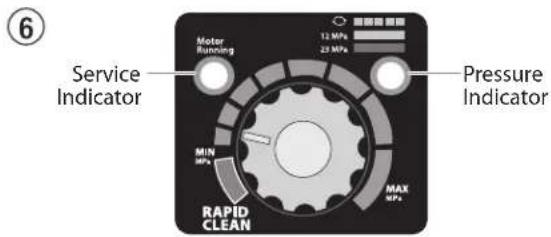
SERVICE INDICATOR
The Service indicator is on when the motor is commanded to run. This indicator is used by service centers to troubleshoot motor problems.
PRESSURE INDICATOR
The pressure indicator shows the current operating pressure of the sprayer. It has three different indications: blinking yellow, solid yellow, and solid green.
Blinking Yellow
When the pressure indicator is blinking yellow, the sprayer is operating between 0 and 1.4 MPa (14 bar). A blinking yellow pressure indicator means:
• The sprayer is plugged in and turned "ON"
• The sprayer is at priming pressure (little or no pressure)
• It is safe to move the relief valve between positions
• It is safe to change or replace the spray tip

If the pressure indicator begins blinking yellow when the pressure control knob is set at a higher pressure and the relief valve is in the SPRAY position, either the spray tip is worn or the sprayer is in need of service/repair.
Solid Yellow
When the pressure indicator is solid yellow, the sprayer is operating between 1.4 MPa (14 bar) and 12 MPa (120 bar). A solid yellow pressure indicator means:
- The sprayer is at the proper pressure setting for spraying stain, lacquer, varnish, and multi-colors
Solid Green
When the pressure indicator is solid green, the sprayer is operating between 12 MPa (120 bar) and 23 MPa (230 bar). A solid green pressure indicator means:
- The sprayer is at the proper pressure setting for spraying oil-based and latex house paints
- The sprayer is operating at peak performance at a high pressure setting
- If the pressure indicator goes to solid yellow when the pressure is set so that it starts at solid green, it indicates one of the following:
a. Tip Wear Indicator — when spraying with latex or at high pressure the solid yellow appears. This means the tip is worn and needs to be replaced.
b. Tip Too Large — when a tip that is too large for the sprayer is put in the gun, the pressure indicator will turn from solid green to solid yellow.
c. Fluid Section Wear — if a solid yellow pressure indicator appears when using a new tip and the pressure is set at maximum, service may be required (worn packings, worn piston, stuck valve, etc...).
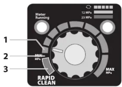
4.3 PRESSURE CONTROL KNOB SETTINGS
- Minimum pressure setting
- Black zone – no pressure generation
- Blue zone – pulsating pressure for cleaning
⑦
4.4 CONNECTION TO THE MAINS NETWORK

The unit must be connected to an appropriately-grounded safety outlet.
Before connecting the unit to the mains supply, ensure that the line voltage matches that specified on the unit's rating plate. The connection must be equipped with a residual current protective device with INF ≤ 30 mA.

Wagner's accessories program also includes a mobile operator protection device for the electronic supply, which can also be used with other electronic equipment.
4.5 CLEANING PRESERVING AGENT WHEN STARTING-UP OF OPERATION INITIALLY
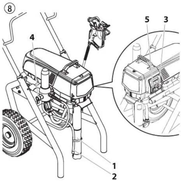
- Immerse the suction tube (Fig. 8, Item 2) return hose (1) into a container with a suitable cleaning agent.
- Turn the pressure control knob counterclockwise (3) to minimum pressure.
- Open the relief valve (4), valve position PRIME (circulation).
- Switch the unit (5) ON.
- Wait until the cleaning agent exudes from the return hose.
- Close the relief valve, valve position SPRAY ( ^27 spray).
- Pull the trigger of the spray gun.
- Spray the cleaning agent from the unit into an open collecting container.
4.6 TAKING THE UNIT INTO OPERATION WITH COATING MATERIAL
-
Immerse the suction tube (Fig. 8, Item 2) and return hose (1) into the coating material container.
-
Turn the pressure control knob counterclockwise (3) to minimum pressure.
-
Open the relief valve (4), valve position PRIME (circulation).
-
Switch the unit (5) ON.
-
Wait until the coating material exudes from the return hose.
-
Close the relief valve, valve position SPRAY ( ^37 spray).
-
Trigger the spray gun several times and spray into a collecting container until the coating material exits the spray gun without interruption.
-
Increase the pressure by slowly turning up the pressure control knob.
Check the spray pattern and increase the pressure until the atomization is correct.
Always turn the pressure control knob to the lowest setting with good atomization.
- The unit is ready to spray.
4.7 DIGITAL ELECTRONIC SPRAY CONTROL (DESC)
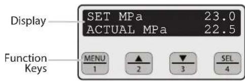
| [SHST] | The Digital Electronic Spray Control (DESC) increases the functionality of the sprayer. It is installed directly below the pressure control knob on the control panel. It consists of a display and four function keys. The display shows various menu screens that allow the user to customize and monitor sprayer operation using the function keys. |

| The pressure control knob overrides the Digital Electronic Spray Control (DESC) settings.Anytime the pressure control knob is turned, the sprayer pressure will change accordingly. |
FUNCTION KEYS
The function keys are numbered 1–4. Each key is labeled with an additional function as well.
| #1/Menu Key Pressing the #1 key scrolls through the available menu screens or performs a function described on the active menu screen. | |
| #2/▲ Key | Pressing the #2 key performs a function described on the active menu screen or increases a value. |
| #3/▼ Key | Pressing the #3 key performs a function described on the active menu screen or decrease a value. |
| #4/Select Key | Pressing the #4 key selects the active menu screen or performs a function described on the active menu screen. |
MENU SCREENS
Several menu screens are available for the user to customize and monitor sprayer operation. They include Main Screen, Volume Pumped, Job Volume, Unit Serial #, Timers, Job Timers, Service Time, Security Code, Prime, and Rapid Clean.
MAIN SCREEN
The Main Screen is the default screen for the control system at sprayer startup. Pressing the #2 key switches between PSI, BAR and MPa units of
SET MPa 23.0 ACTUAL MPa 22.5
measure. Press the #1 key to scroll through the remaining menu screens.

For sprayers equipped with an nine-language Digital Electronic Spray Control (DESC):
Pressing the #2 key at the Main Screen switches between PSI, Bar and MPa units of measure.
Pressing the #3 key at the Main Screen changes the language of the text on the display. There are a total of nine languages available. Each time the #1 key is pressed, a different language will appear. The languages, in order of appearance, are: English, Spanish, Dutch, Danish, Swedish, German, French, Italian, and Portuguese.
VOLUME PUMPED SCREEN
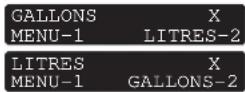
The Volume Pumped screen shows the total number of gallons or liters sprayed by the sprayer.
To select the Volume Pumped screen, press the #4 key.

JOB VOLUME SCREEN
The Job Volume screen allows the user to reset a liter counter to track usage on specific jobs.
To select the Job Volume screen, press the #4 key.


UNIT SERIAL # SCREEN
The Unit Serial # screen shows the sprayers serial number.
To select the Unit Serial # screen, press the #4 key.


TIMERS SCREEN
The Timers screen shows the total time the sprayer has been turned on as well as the total time the sprayer has been running (pumping).
To select the Timers screen, press the #4 key.


JOB TIMERS SCREEN
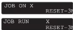
The Job Timers screen allows the user to reset the "ON TIME" and "RUN TIME" to track time on specific jobs.
To select the Job Timers screen, press the #4 key. "JOB ON" screen will appear. Press #3 to reset. Press #1 to continue to "JOB RUN" screen.
Press #3 to reset. Press #1 to scroll through the remaining menu screens.

SERVICE TIME SCREEN
The Service Time screen allows the user to set a service time interval (in hours). Below the set time, the
screens shows the current amount of hours on the sprayer since the last activation of the service timer. To select the Service Timer screen, press the #4 key.
To set the service time, press the #2 (up) and/or the #3 (down) keys to the desired time (run hours will increase/
decrease in increments of 25 for each time you press a key).
When the sprayer reaches the SERVICE@ time selected, the screen will display "SERVICE DUE". To reset the timer, press the #3 key when the pump is first turned on. This will reset the "SERVICE DUE" message and also reset the "SERVICE TIME" to the previous setting.


SECURITY CODE SCREEN
The Security Code screen allows the user to set a four digit security code to prevent unauthorized use of the
sprayer. If a security code has been set, the control system display will ask for the code at startup. If the correct code is entered, the display will show the Main Screen and the sprayer will operate. If the wrong code is entered, the display will continue to ask for the correct code and the sprayer will not work. To set or change the security code, press the #2 key.


If the sprayer is new, no security code is set and the Main Screen will appear at startup. When setting a security code for the first time, the "Enter Old Code Number" screen will appear, and you will need to enter "1111".
Enter the old security code number to access the screen that allows the code change. If the wrong code is entered, the display will continue to ask for the correct code and the security code cannot be changed.
Enter the new security code. Once the new code is entered, the display will automatically ask that the new code be re-entered for verification. If the same new code is re-entered, the display will confirm that the new
ENTER NEW CODE NUMBER XXXX
RE-ENTER NEW NUMBER XXXX
NEW CODE NUMBER ACCEPTED
code has been accepted and return to the Main Screen. If the new code is re-entered incorrectly, the display will return to the "Enter New Code Number" screen and the process will repeat. If you forget or misplace your security code, you can contact Wagner customer service for assistance.

To inactivate the security function, enter "1111" at the "Enter New Code Number" screen (this is the default code that leaves the sprayer unlocked). As a result, the Main Screen will appear at sprayer startup.
PRIme ScReeN
The Prime screen appears when the pressure control knob is set at the "MIN" setting.
PRIME
RAPId cLeAN ScReeN
The Rapid Clean screen appears when the pressure control knob is set at the RAPID CLEAN position and the PRIME/SPRAY valve is in the PRIME position.
RAPID CLEAN

If there is no action at any menu screen for 30 seconds, the display will go back to the Main Screen.
5 SPRAyING

Injection hazard. Do not spray without the tip guard in place. NEVER trigger the gun unless the tip is completely turned to either the spray or the unclog position. ALWAYS engage the gun trigger lock before removing, replacing or cleaning tip.
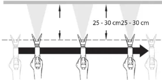
A) The key to a good paint job is an even coating over the entire surface. Keep your arm moving at a constant speed and keep the spray gun at a constant distance from the surface. The best spraying distance is 10-12 inches (25 to 30 cm) between the spray tip and the surface.
A
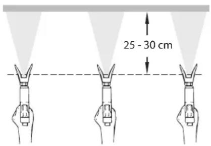
B) Keep the spray gun at right angles to the surface. This means moving your entire arm back and forth rather than just flexing your wrist.
Keep the spray gun perpendicular to the surface, otherwise one end of the pattern will be thicker than the other.
B
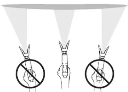
c) Trigger gun after starting the stroke. Release the trigger before ending the stroke. The spray gun should be moving when the trigger is pulled and released. Overlap each stroke by about 30%. This will ensure an even coating.
C
i
If very sharp edges result or if there are streaks in the spray jet – increase the operating pressure or dilute the coating material.
6 HANdLING The HIGH-PReSSuRe HoSe
 | The unit is equipped with a high-pressure hose specially suited for piston pumps. |
 | Danger of injury through leaking high-pressure hose. Replace any damaged high-pressure hose immediately.Never repair defective high-pressure hoses yourself! |
The high-pressure hose is to be handled with care. Avoid sharp bends and folds: the smallest bending radius is about 8" (20 cm).
Do not drive over the high-pressure hose. Protect against sharp objects and edges.
Never pull on the high-pressure hose to move the device.
Make sure that the high-pressure hose cannot twist. This can be avoided by using a Wagner spray gun with a swivel joint and a hose system.
| When using the high-pressure hose while working on scaffolding, it is best to always guide the hose along the outside of the scaffolding. | |
| The risk of damage rises with the age of the high-pressure hose. Wagner recommends replacing high-pressure hoses after 6 years. | |
| Use only Wagner original-high-pressure hoses in order to ensure functionality, safety and durability. |
7 INTeRRuPTIoN oF WoRK
- Open the relief valve, valve position PRIME (○ circulation).
- Switch the unit OFF.
- Turn the pressure control knob counterclockwise to minimum pressure.
- Pull the trigger of the spray gun in order to release the pressure from the high-pressure hose and spray gun.
- Secure the spray gun, refer to the operating manual of the spray gun.
- If a standard tip is to be cleaned, see Page 61, Section 12.2. If a non-standard tip is installed, proceed according to the relevant operating manual.
- Depending on the model, leave the suction tube or the suction hose and return hose immersed in the coating material or swivel or immerse it into a corresponding cleaning agent.

If fast-drying or two-component coating material is used, ensure that the unit is rinsed with a suitable cleaning agent within the processing time.
8 CLEANING THE UNIT (SHUTTING DOWN)
 | A clean state is the best method of ensuring operation without problems. After you have finished spraying, clean the unit. Under no circumstances may any remaining coating material dry and harden in the unit. |
 | The cleaning agent used for cleaning (only with an ignition point above 38 °C) must be suitable for the coating material used. |
 | Secure the spray gun, refer to the operating manual of the spray gun.Clean and remove tip.For a standard tip, refer to Page 61, Section 12.2.If a non-standard tip is installed, proceed according to the relevant operating manual. |
- Remove suction hose from the coating material.
- Close the relief valve, valve position SPRAY ( ≥slant spray).
- Switch the unit ON.
 Attention Attention | The container must be earthed in case of coating materials which contain solvents. |
 | Caution! Do not pump or spray into a container with a small opening (bunghole)! |
- Pull the trigger of the spray gun in order to pump the remaining coating material from the suction hose, high-pressure hose and the spray gun into an open container.
- Immerse suction hose with return hose into a container with a suitable cleaning agent.
- Turn the pressure control knob counterclockwise to minimum pressure.
- Open the relief valve, valve position PRIME (circulation).
- Pump a suitable cleaning agent in the circuit for a few minutes.
- Close the relief valve, valve position SPRAY ( ^7 spray).
- Pull the trigger of the spray gun.
- Pump the remaining cleaning agent into an open container until the unit is empty.
- Switch the unit OFF.
8.1 CLEANING UNIT FROM OUTSIDE
 | First of all pull out mains plug from socket. |
 | Danger of short circuit through penetrating water!Never spray down the unit with high-pressure or high-pressure steam cleaners.Do not put the high-pressure hose into solvents. Use only a wet cloth to wipe down the outside of the hose. |
Wipe down unit externally with a cloth which has been immersed in a suitable cleaning agent.
8.2 CLEANING THE INLET SCREEN
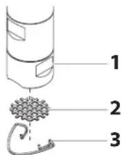
 | The inlet screen will clog and must be cleaned at least once a day. |
- Remove the retaining ring (3) from the foot valve (1) housing.
- Remove the inlet screen (2) from the foot valve housing (1).
- Clean thoroughly with the appropriate solvent.
⑨
8.3 cLeANING THE HIGH-PReSSuRe FILTeR

Clean the filter cartridge regularly. A soiled or clogged high-pressure filter can cause a poor spray pattern or a clogged tip.
- Turn the pressure control knob counterclockwise to minimum pressure.
- Open the relief valve, valve position PRIME (circulation).
- Switch the unit OFF.

Unplug the power plug from the outlet.
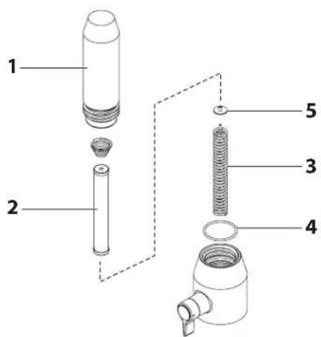
- Unscrew the filter housing (Fig. 10, Item 1). with a strap wrench.
- Pull the filter cartridge (2) from the bearing spring (3).
- Clean all the parts with the corresponding cleaning agent. If necessary, replace the filter cartridge.
- Check the O-ring (4), replace it if necessary.
- Place the bearing ring (5) against the bearing spring (3). Slide the filter cartridge (2) over the bearing spring.
- Screw in filter housing (1) and tighten it as far as possible with the strap wrench.
10
8.4 cLeANING AIRLeSS SPRAy GuN

Clean the spray gun after each use.
- Rinse airless spray gun with an appropriate cleaning agent.
- Clean tip thoroughly with appropriate cleaning agent so that no coating material residue remains.
- Thoroughly clean the outside of the airless spray gun.
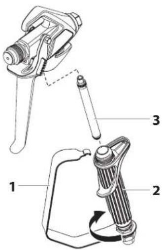
INTAKe FILTeR IN AIRLeSS SPRAy GuN (FIG. 11)
- Unclip the top of the trigger guard (1) from the gun head.
- Using the bottom of the trigger guard as a wrench, loosen and remove the handle assembly (2) from the gun head.
- Pull the old filter (3) out of the gun head. Clean or replace.
- Slide the new filter, tapered end first, into the gun head.
- Thread the handle assembly into the gun head. Tighten with the trigger wrench.
- Snap the trigger guard back onto the gun head.
11
9 REMEDY IN CASE OF FAULTS
| Type of malfunction | Possible cause | Measures for eliminating the malfunction |
| A. Unit does not start | 1. No voltage applied.2. Pressure setting too low.3. ON/OFF switch defective. | 1. Check voltage supply.2. Turn up pressure control knob.3. Replace. |
| B. Unit does not draw in material | 1. Relief valve is set to SPRAY (spray).2. Filter projects over the fluid level and sucks air.3. Filter clogged.4. Suction hose/suction tube is loose, i.e. the unit is sucking in outside air. | 1. Set relief valve to PRIME (circulation).2. Refill the coating material.3. Clean or replace the filter.4. Clean connecting points. Replace O-rings if necessary.Secure suction hose with retaining clip. |
| C. Unit draws in material, but the pressure does not build up | 1. Tip heavily worn.2. Tip too large.3. Pressure setting too low.4. Filter clogged.5. Coating material flows through the return hose when the relief valve is in the SPRAY (spray) position.6. Packings sticky or worn.7. Valve balls worn.8. Valve seats worn. | 1. Replace2. Replace tip.3. Turn pressure control knob clockwise to increase.4. Clean or replace the filter.5. Remove and clean or replace relief valve.6. Remove and clean or replace packings.7. Remove and replace valve balls.8. Remove and replace valve seats. |
| D. Coating material exits at the top of the fluid section | 1. Upper packing is worn.2. Piston is worn. | 1. Remove and replace packing.2. Remove and replace piston. |
| E. Increased pulsation at the spray gun | 1. Incorrect high-pressure hose type.2. Tip worn or too large.3. Pressure too high. | 1. Only use WAGNER original-high-pressure hoses in order to ensure functionality, safety and durability.2. Replace tip.3. Turn pressure control knob to a lower number. |
| F. Poor spray pattern | 1. Tip is too large for the coating material which is to be sprayed.2. Pressure setting incorrect.3. Volume too low.4. Coating material viscosity too high. | 1. Replace tip.2. Turn pressure control knob until a satisfactory spraying pattern is achieved.3. Clean or replace all filters.4. Thin out according to the manufacturer's instructions. |
| G. Unit loses power | 1. Pressure setting too low. | 1. Turn pressure control knob clockwise to increase. |
| H. Pump over-pressurizes and will not shut off. | 1. Pressure switch defective.2. Transducer defective. | 1. Take unit to a Wagner authorized service center.2. Take unit to a Wagner authorized service center. |
10 SeRVIcING
10.1 GeNeRAL SeRVIcING
Servicing of the unit should be carried out once annually by the WAGNER service.
- Check high-pressure hoses, device connecting line and plug for damage.
- Check the inlet valve, outlet valve and filter for wear.
10.2 HIGH-PReSSuRe HoSe
Inspect the high-pressure hose visually for any notches or bulges, in particular at the transition in the fittings. It must be possible to turn the union nuts freely.

The risk of damage rises with the age of the high-pressure hose. Wagner recommends replacing high-pressure hoses after 6 years.
11 RePAIRS AT THE uNIT
| Switch the unit OFF.Before all repair work: Unplug the power plug from the outlet. | |
 | Make sure to check for grounding continuity after service is performed on any electrical components.Use an ohmmeter to determine that there is continuity between accessible dead-metal parts of the product and the grounding blade of the attachment plug. |
11.1 ReLleF VALVe
| Attention | The valve housing (4) should not be repaired. If worn, it should always be replaced with a new one. |
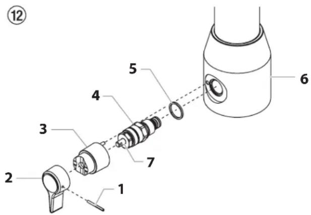
- Use a drift punch of 2 mm to remove the grooved pin (Fig. 12, Item 1) from the relief valve handle (2).
- Remove the relief valve handle (2) and cam base (3).
- Using a wrench, remove the valve housing (4) from the pump manifold (6).
- Ensure that the seal (5) is seated correctly, then screw the new valve housing (4) completely into the pump manifold (6). Tighten securely with a wrench.
- Align the cam base (3) with the hole in the pump manifold (6). Lubricate the cam base with grease and slide on the cam base.
- Bring the hole in the valve shaft (7) and in the relief valve handle (2) into alignment.
- Insert the grooved pin (1) to secure the relief valve handle in position.
11.2 INLeT AND ouTLeT VALVe
- Remove the four screws in the front cover and then remove the front cover.

Danger of crushing - do not reach with the fingers or tool between the moving parts.
- Turn the pressure control knob to minimum pressure. The Digi-Trac™ screen should say "PRIME".
- Press the #1 key on the Digi-Trac™ control panel. The "CREEP MODE" screen will now appear.
- Slowly turn the pressure control knob clockwise to increase the pressure. The crankshaft/slider assembly will begin to move very slowly.
- When it reaches the bottom, dead-center of its stroke, turn the pressure control knob back to minimum pressure. The crankshaft/slider assembly should stop.
- Unplug the power plug from the outlet.
- Pull off clamp on suction tube and remove return hose.
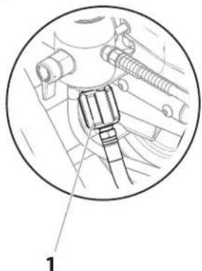
- Unscrew the connection hose (Fig. 14, item 1) from the high-pressure filter.
- Turn the knob on the side of the cart clockwise to unlock the cart. Tilt the cart backwards until it locks into place.
- Loosen and remove the inlet valve housing (2) from the upper housing.
- Remove bearing ring (3), O-ring (4), O-ring (5), inlet valve seat (6), inlet valve ball (7) and upper ball guide (8).
- Clean all the parts with the corresponding cleaning agent.
Check the inlet valve housing (2), inlet valve seat (6) and inlet valve ball (7) for wear and replace the parts if necessary. If the worn inlet valve seat (6) is unused on one side, install it the other way around.
14
natural_image
Technical diagram of a mechanical assembly with labeled component (1), showing no readable text or symbols beyond the number marker.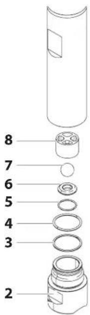
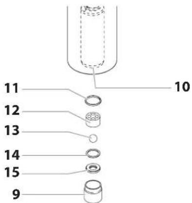
- Screw out outlet valve housing (Fig 15, item 9) from the piston (10) with 3/8 inch hexagon socket head wrench.
- Remove the upper seal (11), upper ball guide (12), outlet valve ball (13), washer (14) and outlet valve seating (15).
- Clean all the parts with the corresponding cleaning agent. Check outlet valve housing (9), outlet valve seat (15), outlet valve ball (13) and upper ball guide (12) for wear and replace parts if necessary. If the worn outlet valve seat (15) is unused on one side, install it the other way around.
- Carry out installation in the reverse order.
- If you plan to replace the fluid section packings, move on to section 11.3. If not, reassemble fluid section in the reverse order of how it was disassembled.
15
11.3 PAcKINGS
- Remove inlet valve housing in accordance with the steps in Chapter 11.2, Page 56.
- It is not necessary to remove the outlet valve.
- Pull the lever on the underside of the sprayer toward the front of the sprayer. This will un-clamp the entire fluid section.
- Slide the fluid section forward to remove it from the gear housing.
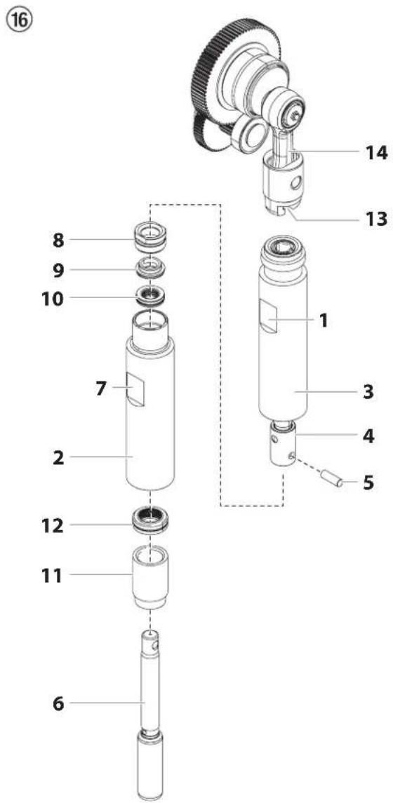
- Place the fluid section cylinder upright in a vise by clamping on the wrench flats (Fig. 16, Item 1).

Do not over-tighten the vise. Damage to the cylinder may occur.
-
Turn the upper housing (2) counterclockwise to loosen it from the cylinder (3).
-
Slowly pull down the upper housing (2) just far enough to expose the extension slider (4) and the connecting pin (5) that connects the piston rod (6) to the extension slider (4).
-
Push the connecting pin out of the extension slider and piston rod and remove the piston rod and upper housing.
-
Place the upper housing upright in a vise by clamping on the wrench flats (7).

Do not over-tighten the vise. Damage to the upper housing may occur.
- Using a wrench, remove the upper seal retainer (Fig. 16, Item 8).
- Slide the piston rod (6) out through the bottom of the upper housing (2).
- Inspect the piston rod (6) for wear and replace if necessary.
- Remove the upper support ring (9) and upper packing assembly (10) from the top of the upper housing (2).
- Remove the adapter (11) and lower packing assembly (12) from the bottom of the upper housing.

Be careful not to scratch, score, or otherwise damage the upper housing during removal of the packings.
- Clean the upper housing (2) and cylinder (3-5). Inspect the upper housing and cylinder for damage and replace if necessary.
- Place the upper housing upright (2) in a vise by clamping on the wrench flats (7).
- Locate the new upper and lower packings and remove the pre-form tools. Save the upper packing pre-form tool for use as the piston insertion tool later in this procedure.

Do not remove the pre-form tools from the upper and lower packings until immediately before they are installed into the upper housing.
- Lubricate upper packing (10) and lower packing (12) with machine grease.
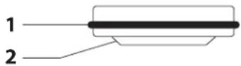
- Insert upper packing (Fig. 17) with O-ring (1) and protruding lip (2) downward.
17
-
Insert upper support ring (9) on top of the upper packing (10)
-
Thread the upper seal retainer (8) into the upper housing (2).
-
Rotate the upper housing in the vise so that the bottom end is facing up.
-
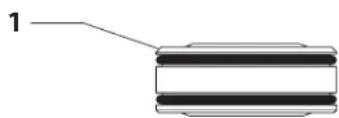
Insert the lower packing (Fig. 18) partially into the bottom of the cylinder with the large beveled edge (1) facing toward the cylinder (beveled edge will be facing up when the cylinder is upright).
18
natural_image
Pure diagram of a cylindrical object with two horizontal bands and a labeled line (no text or symbols)- Push the lower packing assembly (Fig. 16, Item 12) into position using the lower packing insertion tool (see Fluid Section Assembly parts list for lower packing insertion tool P/N).

Coat the piston insertion tool (i.e. upper packing pre-form tool) and the piston rod with grease before inserting them into the upper housing.
-
Place the piston insertion tool over the top of the piston rod (6).
-
Insert the piston rod (6) into the bottom of the upper housing (2), through the lower packing assembly (12), through the upper packing assembly (10), and out through the upper seal retainer (8).

Make sure the raised lip on the bottom of the lower packing is fully outside the packing around the piston rod after insertion of the piston rod.
-
Remove the piston insertion tool from the top of the piston rod (6).
-
Lubricate the threads on the upper housing with anti-seize compound. Remove the upper housing from the vise.
- Insert the piston rod into the extension slider. When the connecting pin hole on the piston rod lines up with the hole in the extension slider, insert the connecting pin.
- Thread the upper housing into the cylinder, turning clockwise.
- Continue to turn the upper housing clockwise until it is flush against the cylinder.
- Replace the cylinder (3) back into the fluid section clamp on the gear housing. Make sure to slide the top of the piston rod extension into the T-slot (13) on the slider assembly (14).
- Push the lever on the underside of the unit toward the rear of the sprayer to lock the fluid section back into place.
- Insert the adapter (Fig. 16, item 11) into the bottom of the upper housing.
- Making sure that the bearing ring (Fig. 14, item 3) and O-rings (Fig. 14, items 4-5) are lubricated and in place, reassemble the inlet valve assembly and and thread it into the upper housing. Tighten the inlet valve housing until the o-ring engages, then continue to tighten until snug. Once snug, tighten an additional 1/8–1/4 turn.
- Replace the connection hose to the fitting on the high-pressure filter.
- Replace the return hose into the clamp on the siphon tube.
- Install front cover.
11.4 PS 3.39 coNNecTloN dIAGRAM
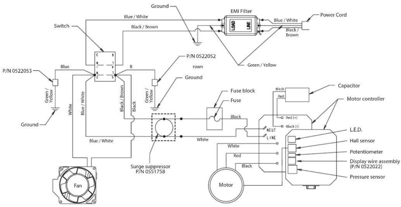
11.5 dIGITAL eLecTRoNlc SPRAy coNTRoL (deSc) eRRoR meSSAGeS
The following error message screens appear whenever the Digital Electronic Spray Control (DESC) detects a problem with the sprayer. Once a problem occurs and the error message appears, the sprayer will shut down.

Before proceeding, relieve any pressure remaining in the system (valve position PRIME O). Additionally, follow all other warnings to reduce the risk of an injection injury, injury from moving parts or electric shock. Always unplug the sprayer before servicing!
cHecK TRANSduceR ScReeN
The Check Transducer screen appears
CHECK
TRANSDUCER
when the transducer has become disconnected or is defective. Take the sprayer to a Wagner authorized service center for repair.
cHecK PoTeNTlomeTeR ScReeN
The Check Potentiometer screen appears when the potentiometer has become disconnected or is defective. Take the sprayer to a Wagner authorized service center for repair.
cHecK moToR ScReeN
Indicates the motor is shut down due
CHECK
MOTOR
to connection problems between the motor and controller. Take the sprayer to a Wagner authorized service center for repair.
LoW VoLTAGe ScReeN
The Low Voltage screen appears when
LOW
VOLTAGE
the sprayer shuts down because of low input voltage. Check the power supply and correct the problem. Restart the sprayer.
HIGH moToR TemPeRATuRe ScReeN
The High Motor Temperature screen
appears when the temperature of the motor has risen too high. Take the sprayer to a Wagner authorized service center for repair.
HIGH MOTOR
TEMPERATURE
HIGH mecHANlcAL LoAd
The High Mechanical Load screen
appears when the sprayer shuts down
because of high current or when the sprayer goes into current fold back mode. Take the sprayer to a Wagner authorized service center for repair.
HIGH MECHANICAL
LOAD
HIGH coNTRoL TemPeRATuRe ScReeN
Indicates the DESC is shut down due to
excessive heat. Take the sprayer to a
Wagner authorized service center for repair.
HIGH CONTROL
TEMPERATURE
BAd HALL cycLe PoWeR ScReeN
Indicates the motor or motor hall
affect sensors are defective. Take the
sprayer to a Wagner authorized service center for repair.
BAD HALL CYCLE
POWER
12 APPENDIX
12.1 SELECTION OF TIP
To achieve faultless and rational working, the selection of the tip is of the greatest importance.
In many cases the correct tip can only be determined by means of a spraying test.
SOME RULES FOR THIS:
The spray jet must be even.
If streaks appear in the spray jet the spraying pressure is either too low or the viscosity of the coating material to high.
REMEDY: Increase pressure or dilute coating material. Each pump conveys a certain quantity in proportion to the size of the tip:
The following principle is valid: large tip = low pressure small tip = high pressure
There is a large range of tips with various spraying angles.
12.2 SERVICING AND CLEANING OF AIRLESS HARD-METAL TIPS
STANDARD TIPS
If a different tip type has been fitted, then clean it according to manufacturer's instructions.
The tip has a bore processed with the greatest precision. Careful handling is necessary to achieve long durability. Do not forget the fact that the hard-metal insert is brittle! Never throw the tip or handle with sharp metal objects.
The following points must be observed to keep the tip clean and ready for use:
- Turn the relief valve handle fully counterclockwise (○ Circulation).
- Remove the tip from the spray gun.
- Place tip in an appropriate cleaning agent until all coating material residue is dissolved.
- If there is high-pressure air available, blow out tip.
- Remove any residue by means of a sharp wooden rod (toothpick).
- Check the tip with the help of a magnifying glass and, if necessary, repeat points 3 to 5.
12.3 SPRAY GUN ACCESSORIES
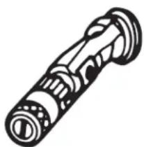
natural_image
Illustration of a mechanical device with no visible text or symbolsFlat jet adjusting tip
up to 250 bar (25 MPa
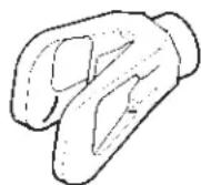
Contact protection
for the flat jet
adjustment tip
Order No. 0097 294
| Tip marking | Bore mm | Spray width at about 30 cm removal of spray objectPressure 100 bar (10 MPa) | Use | Flat jet adjusting tip Order No. |
| 15 | 0.13 - 0.46 | 5 - 35 cm | Paints | 0999 057 |
| 20 | 0.18 - 0.48 | 5 - 50 cm | Paints, fillers | 0999 053 |
| 28 | 0.28 - 0.66 | 8 - 55 cm | Paints, dispersions | 0999 054 |
| 41 | 0.43 - 0.88 | 10 - 60 cm | Rust protection paints - dispersions | 0999 055 |
| 49 | 0.53 - 1.37 | 10 - 40 cm | Large-area coats | 0999 056 |
Tip extension with slewable knee joint (without tip)
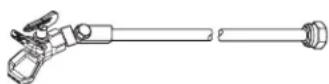
Length: 100 cm
Length: 200 cm
Length: 300 cm
Order no. 0096 015
Order no. 0096 016
Order no. 0096 017
Tip extension

15 cm, F-thread, Order no. 0556 051
30 cm, F-thread, Order no. 0556 052
45 cm, F-thread, Order no. 0556 053
60 cm, F-thread, Order no. 0556 054
15 cm, G-thread, Order no. 0556 074
30 cm, G-thread, Order no. 0556 075
45 cm, G-thread, Order no. 0556 076
60 cm, G-thread, Order no. 0556 077
12.4 AIRLESS TIP TABLE
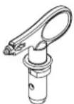
Wagner
TradeTip 3 tip
up to 270 bar
(27 MPa)
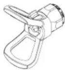
without tip
F thread (11/16 - 16 UN)
for Wagner spray guns
Order no. 0289391
without tip
G thread (7/8 - 14 UN)
for Graco/Titan spray guns
Order no. 0289390

All of the tips in the table below are supplied together with the appropriate gun filter.
| Application Tip marking Spray | angle | Bore inch / mm | Spraying width mm 1) | Gun filter Order | no. | |
| Water-thinnable and solvent-based paints and varnishes, oils, separating agents | 107 | 10^ | 0.007 / 0.18 | 100 | red | 0553107 |
| 207 | 20^ | 0.007 / 0.18 | 120 | red | 0553207 | |
| 307 | 30^ | 0.007 / 0.18 | 150 | red | 0553307 | |
| 407 | 40^ | 0.007 / 0.18 | 190 | red | 0553407 | |
| 109 | 10^ | 0.009 / 0.23 | 100 | red | 0553109 | |
| 209 | 20^ | 0.009 / 0.23 | 120 | red | 0553209 | |
| 309 | 30^ | 0.009 / 0.23 | 150 | red | 0553309 | |
| 409 | 40^ | 0.009 / 0.23 | 190 | red | 0553409 | |
| 509 | 50^ | 0.009 / 0.23 | 225 | red | 0553509 | |
| 609 | 60^ | 0.009 / 0.23 | 270 | red | 0553609 | |
| Synthetic-resin paintsPVC paints | 111 | 10^ | 0.011 / 0.28 | 100 | red | 0553111 |
| 211 | 20^ | 0.011 / 0.28 | 120 | red | 0553211 | |
| 311 | 30^ | 0.011 / 0.28 | 150 | red | 0553311 | |
| 411 | 40^ | 0.011 / 0.28 | 190 | red | 0553411 | |
| 511 | 50^ | 0.011 / 0.28 | 225 | red | 0553511 | |
| 611 | 60^ | 0.011 / 0.28 | 270 | red | 0553611 | |
| Paints, primersFillers | 113 | 10^ | 0.013 / 0.33 | 100 | red | 0553113 |
| 213 | 20^ | 0.013 / 0.33 | 120 | red | 0553213 | |
| 313 | 30^ | 0.013 / 0.33 | 150 | red | 0553313 | |
| 413 | 40^ | 0.013 / 0.33 | 190 | red | 0553413 | |
| 513 | 50^ | 0.013 / 0.33 | 225 | red | 0553513 | |
| 613 | 60^ | 0.013 / 0.33 | 270 | red | 0553613 | |
| 813 | 80^ | 0.013 / 0.33 | 330 | red | 0553813 | |
| FillersRust protection paints | 115 | 10^ | 0.015 / 0.38 | 100 | yellow | 0553115 |
| 215 | 20^ | 0.015 / 0.38 | 120 | yellow | 0553215 | |
| 315 | 30^ | 0.015 / 0.38 | 150 | yellow | 0553315 | |
| 415 | 40^ | 0.015 / 0.38 | 190 | yellow | 0553415 | |
| 515 | 50^ | 0.015 / 0.38 | 225 | yellow | 0553515 | |
| 615 | 60^ | 0.015 / 0.38 | 270 | yellow | 0553615 | |
| 715 | 70^ | 0.015 / 0.38 | 300 | yellow | 0553715 | |
| 815 | 80^ | 0.015 / 0.38 | 330 | yellow | 0553815 | |
| Rust protection paintsLatex paintsDispersions | 117 | 10^ | 0.017 / 0.43 | 100 | white | 0553117 |
| 217 | 20^ | 0.017 / 0.43 | 120 | white | 0553217 | |
| 317 | 30^ | 0.017 / 0.43 | 150 | white | 0553317 | |
| 417 | 40^ | 0.017 / 0.43 | 190 | white | 0553417 | |
| 517 | 50^ | 0.017 / 0.43 | 225 | white | 0553517 | |
| 617 | 60^ | 0.017 / 0.43 | 270 | white | 0553617 | |
| 717 | 70^ | 0.017 / 0.43 | 300 | white | 0553717 | |
| 817 | 80^ | 0.017 / 0.43 | 330 | white | 0553817 | |
| Rust protection paintsLatex paintsDispersions | 219 | 20^ | 0.019 / 0.48 | 120 | white | 0553219 |
| 319 | 30^ | 0.019 / 0.48 | 150 | white | 0553319 | |
| 419 | 40^ | 0.019 / 0.48 | 190 | white | 0553419 | |
| 519 | 50^ | 0.019 / 0.48 | 225 | white | 0553519 | |
| 619 | 60^ | 0.019 / 0.48 | 270 | white | 0553619 | |
| 719 | 70^ | 0.019 / 0.48 | 300 | white | 0553719 | |
| 819 | 80^ | 0.019 / 0.48 | 330 | white | 0553819 | |
| 919 | 90^ | 0.019 / 0.48 | 385 | white | 0553919 |
1) Spray width at about 30 cm to the object and 100 bar (10 MPa) pressure with synthetic-resin paint 20 DIN seconds.
| Application Tip marking Spray | angle | Bore inch / mm | Spraying width mm 1) | Gun filter Order no. | ||
| Flame retardant 221 | 20^ | 0.021 / 0.53 | 120 | white | 0553221 | |
| 321 | 30^ | 0.021 / 0.53 | 150 | white | 0553321 | |
| 421 | 40^ | 0.021 / 0.53 | 190 | white | 0553421 | |
| 521 | 50^ | 0.021 / 0.53 | 225 | white | 0553521 | |
| 621 | 60^ | 0.021 / 0.53 | 270 | white | 0553621 | |
| 721 | 70^ | 0.021 / 0.53 | 300 | white | 0553721 | |
| 821 | 80^ | 0.021 / 0.53 | 330 | white | 0553821 | |
| Roof coatings 223 | 20^ | 0.023 / 0.58 | 120 | white | 0553223 | |
| 323 | 30^ | 0.023 / 0.58 | 150 | white | 0553323 | |
| 423 | 40^ | 0.023 / 0.58 | 190 | white | 0553423 | |
| 523 | 50^ | 0.023 / 0.58 | 225 | white | 0553523 | |
| 623 | 60^ | 0.023 / 0.58 | 270 | white | 0553623 | |
| 723 | 70^ | 0.023 / 0.58 | 300 | white | 0553723 | |
| 823 | 80^ | 0.023 / 0.58 | 330 | white | 0553823 | |
| Thick-film materials,Corrosion protectionSpray filler | 225 | 20^ | 0.025 / 0.64 | 120 | white | 0553225 |
| 325 | 30^ | 0.025 / 0.64 | 150 | white | 0553325 | |
| 425 | 40^ | 0.025 / 0.64 | 190 | white | 0553425 | |
| 525 | 50^ | 0.025 / 0.64 | 225 | white | 0553525 | |
| 625 | 60^ | 0.025 / 0.64 | 270 | white | 0553625 | |
| 725 | 70^ | 0.025 / 0.64 | 300 | white | 0553725 | |
| 825 | 80^ | 0.025 / 0.64 | 330 | white | 0553825 | |
| 227 | 20^ | 0.027 / 0.69 | 120 | white | 0553227 | |
| 327 | 30^ | 0.027 / 0.69 | 150 | white | 0553327 | |
| 427 | 40^ | 0.027 / 0.69 | 190 | white | 0553427 | |
| 527 | 50^ | 0.027 / 0.69 | 225 | white | 0553527 | |
| 627 | 60^ | 0.027 / 0.69 | 270 | white | 0553627 | |
| 827 | 80^ | 0.027 / 0.69 | 330 | white | 0553827 | |
| 229 | 20^ | 0.029 / 0.75 | 120 | white | 0553229 | |
| 329 | 30^ | 0.029 / 0.75 | 150 | white | 0553329 | |
| 429 | 40^ | 0.029 / 0.75 | 190 | white | 0553429 | |
| 529 | 50^ | 0.029 / 0.75 | 225 | white | 0553529 | |
| 629 | 60^ | 0.029 / 0.75 | 270 | white | 0553629 | |
| 231 | 20^ | 0.031 / 0.79 | 120 | white | 0553231 | |
| 331 | 30^ | 0.031 / 0.79 | 150 | white | 0553331 | |
| 431 | 40^ | 0.031 / 0.79 | 190 | white | 0553431 | |
| 531 | 50^ | 0.031 / 0.79 | 225 | white | 0553531 | |
| 631 | 60^ | 0.031 / 0.79 | 270 | white | 0553631 | |
| 731 | 70^ | 0.031 / 0.79 | 300 | white | 0553731 | |
| 831 | 80^ | 0.031 / 0.79 | 330 | white | 0553831 | |
| 233 | 20^ | 0.033 / 0.83 | 120 | white | 0553233 | |
| 333 | 30^ | 0.033 / 0.83 | 150 | white | 0553333 | |
| 433 | 40^ | 0.033 / 0.83 | 190 | white | 0553433 | |
| 533 | 50^ | 0.033 / 0.83 | 225 | white | 0553533 | |
| 633 | 60^ | 0.033 / 0.83 | 270 | white | 0553633 | |
| 235 | 20^ | 0.035 / 0.90 | 120 | white | 0553235 | |
| 335 | 30^ | 0.035 / 0.90 | 150 | white | 0553335 | |
| 435 | 40^ | 0.035 / 0.90 | 190 | white | 0553435 | |
| 535 | 50^ | 0.035 / 0.90 | 225 | white | 0553535 | |
| 635 | 60^ | 0.035 / 0.90 | 270 | white | 0553635 | |
| 735 | 70^ | 0.035 / 0.90 | 300 | white | 0553735 | |
| 439 | 40^ | 0.039 / 0.99 | 190 | white | 0553439 | |
| 539 | 50^ | 0.039 / 0.99 | 225 | white | 0553539 | |
| 639 | 60^ | 0.039 / 0.99 | 270 | white | 0553639 | |
| Heavy duty applications 243 | 20^ | 0.043 / 1.10 | 120 | green | 0553243 | |
| 443 | 40^ | 0.043 / 1.10 | 190 | green | 0553443 | |
| 543 | 50^ | 0.043 / 1.10 | 225 | green | 0553543 | |
| 643 | 60^ | 0.043 / 1.10 | 270 | green | 0553643 | |
| 445 | 40^ | 0.045 / 1.14 | 190 | green | 0553445 | |
| 545 | 50^ | 0.045 / 1.14 | 225 | green | 0553545 | |
| 645 | 60^ | 0.045 / 1.14 | 270 | green | 0553645 | |
| 451 | 40^ | 0.051 / 1.30 | 190 | green | 0553451 | |
| 551 | 50^ | 0.051 / 1.30 | 225 | green | 0553551 | |
| 651 | 60^ | 0.051 / 1.30 | 270 | green | 0553651 | |
| 252 | 20^ | 0.052 / 1.32 | 120 | green | 0553252 | |
| 455 | 40^ | 0.055 / 1.40 | 190 | green | 0553455 | |
| 555 | 50^ | 0.055 / 1.40 | 225 | green | 0553555 | |
| 655 | 60^ | 0.055 / 1.40 | 270 | green | 0553655 | |
| 261 | 20^ | 0.061 / 1.55 | 120 | green | 0553261 | |
| 461 | 40^ | 0.061 / 1.55 | 190 | green | 0553461 | |
| 561 | 50^ | 0.061 / 1.55 | 225 | green | 0553561 | |
| 661 | 60^ | 0.061 / 1.55 | 270 | green | 0553661 | |
| 263 | 20^ | 0.063 / 1.60 | 120 | green | 0553263 | |
| 463 | 40^ | 0.063 / 1.60 | 190 | green | 0553463 | |
| 565 | 50^ | 0.065 / 1.65 | 225 | green | 0553565 | |
| 665 | 60^ | 0.065 / 1.65 | 270 | green | 0553665 | |
| 267 | 20^ | 0.067 / 1.70 | 120 | green | 0553267 | |
| 467 | 40^ | 0.067 / 1.70 | 190 | green | 0553467 | |
1) Spray width at about 30 cm to the object and 100 bar (10 MPa) pressure with synthetic-resin paint 20 DIN seconds.
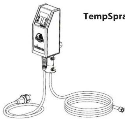
12.5 TEMPSPRAY
The paint material is heated to the required temperature uniformly by an electric heating element, which is located inside the hose (regulated from 20°C to 60°C).
Advantages:
• Constant paint temperature even at low outside temperatures
• Considerably better working of high viscosity coating materials
• Increased application efficiency
• Savings in solvents due to reduction in viscosity
• Adaptable to all airless units
| Order No. | Description |
| 23116592311852 | TempSpray H 126 (ideal for lacquer jobs)Basic unit 1/4" incl. stainless steel hose, DN6, 1/4", 10mSpraypack consisting of: basic unit (2311659), Airless gun AG 14 NPS 1/4", incl. Trade Tip 2 nozzler holder (F-thread) and Trade Tip 2 Fine Finish 410 |
| 23116602311853 | TempSpray H 226 (ideal for dispersions/materials with high viscosity)Basic unit 1/4" incl. Hose reel, heated hose DN10, 15m, hose 1/4" DN4, 1mSpraypack consisting of: Basic unit (2311660), Airless gun AG 14 NPS 1/4", incl. Trade Tip 2 nozzler holder (F-thread) and Trade Tip 2 nozzle 419 |
| 23116612311854 | TempSpray H 326 (ideal for dispersions/materials with high viscosity)Basic unit 1/4" incl. Hose reel, heated hose DN10, 30m, hose 1/4" DN4, 1mSpraypack consisting of: Basic unit (2311661), Airless gun AG 14 NPS 1/4", incl. Trade Tip 2 nozzler holder (F-thread) and Trade Tip 2 nozzle 421 |
natural_image
Line drawing of a temperature sensor device with coiled tubing and connector (no text or symbols on the device itself)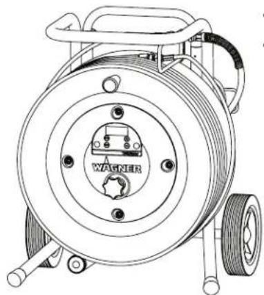
natural_image
Technical line drawing of a mechanical pump or reel assembly with no visible text or symbolsTempSpray H 226
TempSpray H 326
12.6 PUMP-RUNNER
(Order No. 2306987)
Universal accessories for cleaning, clean transportation and preservation of the pump unit.
Features:
- Simpler cleaning – the cleaning liquid circulates constantly through the pump making thorough cleaning of the interior
• No cleaning necessary during work stoppage or change of location because the paint in the pump cannot dry out or leak
• Better protection - Simple assembly
Suitable for the following models:
| Diaphragm Pumps Double-stroke piston pumps | |||
| SF 21 | Finish 270/370 | PS 24 | PS 3.25 |
| SF 23 | Nespray Deco | PS 26 | PS 3.29 |
| SF 27 | Nespray 31 | PS 30 | PS 3.31 |
| SF 31 | PS 34 | PS 3.34 | |
| SF 7000 | |||

Order this at the same time:
EasyClean, cleaning and preservation agent (118ml) Order no. 0508 620.

natural_image
Line drawing of a cylindrical mechanical component with threaded base and top clamped end (no text or symbols)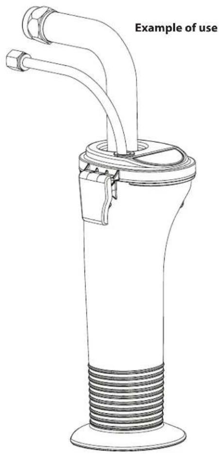
Attention!

3.6 TRANSPORT
3.7 TRANSPORT PAR VÉHICULE
4.2 VOYANTS DU PANNEAU DE COMMANDES
4.6 MISE EN SERVICE DU MATÉRIEL AVEC LE PRODUIT DE REVÊTEMENT
A HEURE X MENU-1 REINI-3 TPS EXE X MENU-1 REINI-3
8.4 NeTToyAGe du PISToLeT AIRLeSS

9 DÉPANNAGE
11.2 cLAPeT d'AdmISSIoN eT de ReFouLemeNT
natural_image
Pure diagram of a mechanical component with no text, numbers, or symbols12.1 CHOIX DES BUSES
natural_image
Line drawing of a mechanical device with no visible text or symbolsnatural_image
Line drawing of a temperature sensor device with coiled tubing and connector (no text or symbols on the device itself)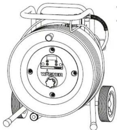
natural_image
Technical line drawing of a mechanical power spool with visible coil and base (no text or symbols)TempSpray H 226
TempSpray H 326
12.6 PUMP-RUNNER
(Réf. No. 2306987)
natural_image
Line drawing of a cylindrical mechanical component with threaded base and mounting bracket (no text or symbols)
natural_image
Technical line drawing of a mechanical device with two pipes and threaded base (no text or symbols)Avvertenza!

4.7 Digital Electronic Spray Control (DESC) 112
3.6 TRASPORTO
3.7 TRASPORTO CON UN VEICOLO
4.2 INDICATORI DEL PANNELLO DI CONTROLLO
4.6 MESSA IN SERVIZIO DELL'APPARECCHIO CON MATERIALE DI COPERTURA
# SER. XXXXXXXXXX MENU-1
VIDEATA TIMERS (TEMPORIZZATORI)
VIdeATA PRIme (INNeSco PomPA)
INNESCO POMPA
8.4 PuLizIA deLL'AeRoGRAFo AIRLeSS

natural_image
Simple diagram of a cylindrical object with two horizontal bands and a labeled line (no text or symbols)natural_image
Illustration of a mechanical device with no visible text or symbolsnatural_image
Line drawing of a temperature sensor device labeled 'TempSpray H 126' with coiled tubing (no text or symbols on the device itself)
natural_image
Line drawing of a mechanical power spool with visible coil and base (no text or symbols)TempSpray H 226 TempSpray H 326
12.6 PUMP-RUNNER
(N° ord. 2306987)
natural_image
Line drawing of a cylindrical mechanical component with threaded base and mounting bracket (no text or symbols)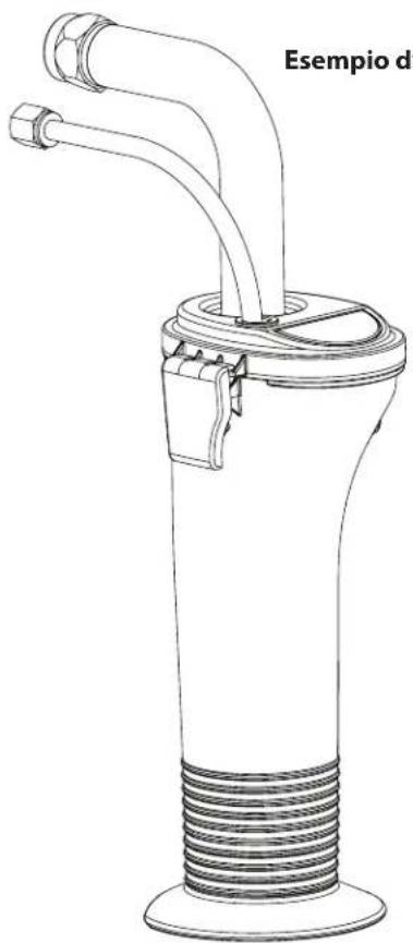
natural_image
Technical line drawing of a mechanical device with coiled tubing and two protruding pipes (no text or symbols)d zuBeHöRBILd GB AcceSSoRleS ILLuSTRATIoN
FILLuSTRATIoN deS AcceSSoIReS I FIGuRA deGLI AcceSSoRI
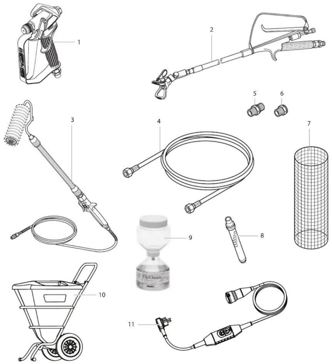
| # | PS 3.39 Benennung Description Description Denominazione | ||||
| 1 | 0538 041 | Spritzpistole Vector Pro 2-Finger | Spray gun, Vector Pro 2-finger | Pistolet Vector Pro 2-doigt | Aerografo Vector Pro 2-dita |
| 0538 040 | Spritzpistole Vector Pro 4-Finger | Spray gun, Vector Pro 4-finger | Pistolet Vector Pro 4-doigt | Aerografo Vector Pro 4-dita | |
| 0538 042 | Spritzpistole Vector Grip 2-Finger | Spray gun, Vector Grip 2-finger | Pistolet Vector Grip 2-doigt | Aerografo Vector Grip 2-dita | |
| 0538 043 | Spritzpistole Vector Grip 4-Finger | Spray gun, Vector Grip 4-finger | Pistolet Vector Grip 4-doigt | Aerografo Vector Grip 4-dita | |
| # | PS 3.39 | Benennung Description Description Denominazione | |||
| 2029 | 46441 | Auslegerpistole 120 cm, G-Gewinde 7/8" | Pole gun 120 cm, G-thread 7/8" Pistolet à rallonge 120 cm, filet F, 7/8" | Aerografo con prolunga da 120 cm, Filettatura G, 7/8" | |
| 0296443 | Auslegerpistole 120 cm, F-Gewinde 11/16" | Pole gun 120 cm, F-thread 11/16" | Pistolet à rallonge 120 cm, filet G, 11/16" | Aerografo con prolunga da 120 cm, Filettatura F, 11/16" | |
| 0296442 | Auslegerpistole 200 cm, G-Gewinde 7/8" | Pole gun 200 cm, G-thread 7/8" Pistolet à rallonge 200 cm, filet F, 7/8" | Aerografo con prolunga da 200 cm, Filettatura F, 11/16" | ||
| 0296444 | Auslegerpistole 200 cm, F-Gewinde 11/16" | Pole gun 200 cm, F-thread 11/16" | Pistolet à rallonge 200 cm, filet G, 11/16" | Aerografo con prolunga da 200 cm, Filettatura F, 11/16" | |
| 3034 | 5010 Inline Roller | IR-100 In-line roller IR-100 Rouleau à alimentation interne | IR-100 | Rullo Inline IR-100 | |
| 4998 | 4573 Hochdruckschlauch DN 4 mm, 7,5 m mit Edelstahnippel | High-pressure hose DN 4 mm, 7.5 m with stainless steel nipple, 1/4" | Flexible à haute pression DN 4 mm, 7.5 m, avec raccords en acier inox, 1/4" | Tubo flessibile ad alta pressione DN 4 mm, 7,5 m, con nipplo di acciaio inossidabile, 1/4" | |
| 9984574 Hochdruckschlauch DN 6 mm, 15 m für Dispersion | High-pressure hose DN 6 mm, 15 m for dispersion, 1/4" | Flexible à haute pression DN 6 mm, 15 m, pour vinyle, 1/4" | Tubo flessibile ad alta pressione DN 6 mm, 15 m, per rivestimento a dispersione, 1/4" | ||
| 9984575 Hochdruckschlauch DN 6 mm, 30 m für Dispersion | High-pressure hose DN 6 mm, 30 m for dispersion, 1/4" | Flexible à haute pression DN 6 mm, 15 m, pour vinyle, 1/4" | Tubo flessibile ad alta pressione DN 6 mm, 30 m, per rivestimento a dispersione, 1/4" | ||
| 5003 | 4038 Doppelstufen zum Kuppeln von Hochdruckschläuchen (1/4" x 1/4") | Double socket for coupling high-pressure hoses (1/4" x 1/4") | Flexible à haute pression DN 6 mm, 30 m, pour vinyle, 1/4" | Raccordi doppio per l'accoppiamento di tubi flessibili ad alta pressione (1/4" x 1/4") | |
| 6003 | 4950 Metex-Reuse Reuse zur Vorfilterung von Beschichtungsstoff im Gebinde. Ansaugrohr direkt in die Reuse stellen. | Metex-Reuse Reuse for pre-filtering of coating material in vessel. Place suction pipe in the reuse. | Tamis Metex. Tamis de préfiltrage du produit dans son bidon d'origine. Mettre le tube d'aspiration directement dans le tamis. | Nassa Metex. Nassa di prefiltraggio del materiale di copertura nella confezione. Collocare il tubo di aspirazione direttamente nella nassa. | |
| 0034952 | Siebpaket (5 Stück) für Lack | Sieve package (5 pcs) for paint | Jeu de filtres (5 pièces) pour laque | Pacchetto di filtri (5 unità) per vernice | |
| 0034951 Siebpaket (5 Stück) für Dispersion | Sieve package (5 pcs) for dispersion | Jeu de filtres (5 pièces) pour vinyle Pacchetto di filtri (5 unità) per materiale a dispersione | |||
| 7003 | 4383 Pistolenfilter, rot, 1 Stück; 180 MA extra fein | Gun filter, red, 1 piece; 180 mesh extra fine | Filtre du pistolet, rouge, 1 pièce; 180 mailles extra-fines | Filtro della pistola, rosso, 1 pezzo; rete 180 extra fine | |
| 0097022 Pistolenfilter, rot, 10 Stück; 180 MA extra fein | Gun filter, red, 10 pieces; 180 mesh extra fine | Filtre du pistolet, rouge, 10 pièces; 180 mailles extra-fines | Filtro della pistola, rosso, 10 pezzi; rete 180 extra fine | ||
| 0043235 Pistolenfilter, gelb, 1 Stück; 100 MA fein | Gun filter, yellow, 1 piece; 100 mesh fine | Filtre du pistolet, jaune, 1 pièce; 100 mailles fines | Filtro della pistola, giallo, 1 pezzo; rete 100 extra fine | ||
| 0097023 Pistolenfilter, gelb, 10 Stück; 100 MA fein | Gun filter, yellow, 10 pieces; 100 mesh fine | Filtre du pistolet, jaune, 10 pièces; 100 mailles fines | Filtro della pistola, giallo, 10 pezzi; rete 100 extra fine | ||
| 0034377 Pistolenfilter, weiß, 1 Stück; 50 MA mittel | Gun filter, white, 1 piece; 50 mesh medium | Filtre du pistolet, blanc, 1 pièce; 50 mailles moyennes | Filtro della pistola, bianco, 1 pezzo; rete 50 media | ||
| 0097024 Pistolenfilter, weiß, 10 Stück; 50 MA mittel | Gun filter, white, 10 pieces; 50 mesh medium | Filtre du pistolet, blanc, 10 pièces; 50 mailles moyennes | Filtro della pistola, bianco, 10 pezzi; rete 50 media | ||
| 0089323 Pistolenfilter, grün, 1 Stück; 30 MA grob | Gun filter, green, 1 piece; 30 mesh coarse | Filtre du pistolet, vert, 1 pièce; 30 mailles grossières | Filtro della pistola, verde, 1 pezzo; rete 30 a grana grossa | ||
| 0097025 Pistolenfilter, grün, 10 Stück; 30 MA grob | Gun filter, green, 10 pieces; 30 mesh coarse | Filtre du pistolet, vert, 10 pièces; 30 mailles grossières | Filtro della pistola, verde, 10 pezzi; rete 30 a grana grossa | ||
| 8009 | 108 TipClean Reinigungset für leichtes Reinigen und zum Schutz von Düsen | TipClean Cleaning Set for easy cleaning and conservation of nozzles | Kit de nettoyage TipClean pour une conservation et un nettoyage faciles des buses | Set di pulizia TipClean per pulizia e conservazione facili degli ugelli | |
| 0508619 | EasyGlide, Spezialöl (118ml) | EasyGlide, special oil (118ml) | EasyGlide, huile spéciale (118 ml) | EasyGlide, olio speciale (118 ml) | |
| 0508620 EasyClean, Reinigungs-und Schutzmittel (118 ml) | EasyClean, cleaning and conservation agent (118 ml) | EasyClean, produit de conservation et de nettoyage (118 ml) | EasyClean, agente per pulizia e conservazione (118 ml) | ||
| 923 | 2909 Personenschutzsicherung PRCD (FI-Sicherung) 230V / 16A (3 m) | Personel protection switch (PRCD) 230V / 16A (3 m) | Interrupteur de protection des personnes (disjoncteur différentiel) 230V / 16A (3 m) | Salvavita 230 V / 16 A (3 m) | |
| 10 | 2309956* | Großmengenbehälter | Large volume container | Bac grands volumes | Recipiente capiente |
| 2312157* | *gleich mitbestellen Anschluss-Set für Großmengenbehälter | Connection kit for large volume container *Order at the same time | Kit de raccordement pour le bac grands volumes *Commander également | Set di raccordi per recipiente capiente *Per aggiungerlo subito all'ordine | |
| 1123 | 12909 Personenschutzsicherung PRCD (FI-Sicherung) 230V / 16A (3 m) | Personel protection switch (PRCD) 230V / 16A (3 m) | Interrupteur de protection des personnes (disjoncteur différentiel) 230V / 16A (3 m) | Salvavita 230 V / 16 A(3 m) | |
d HAuPTBAuGRuPPe GB mAIN ASSemBLy
FeNSemBLE PRINcIPAL IGRuPPo PRINcIPALe
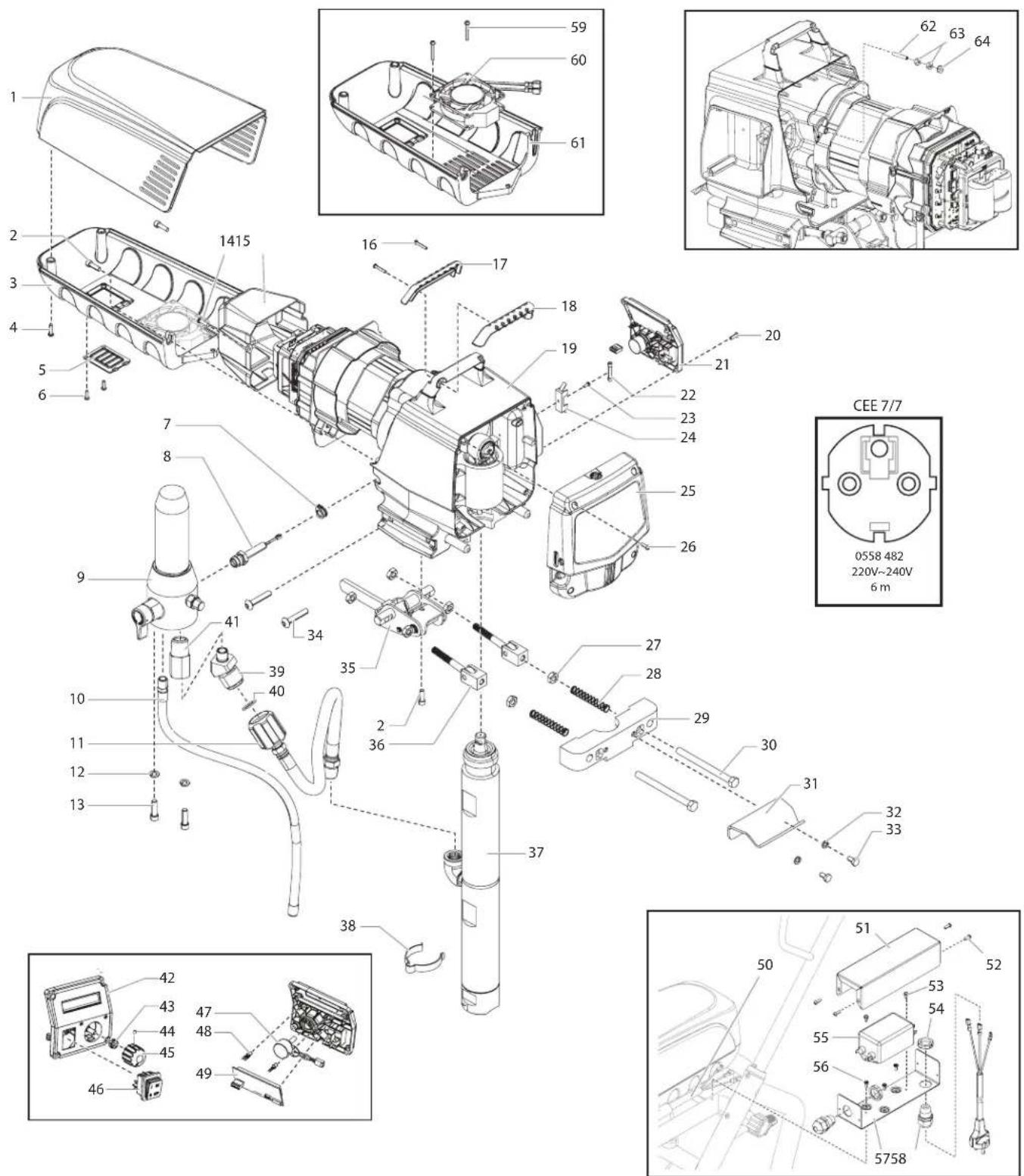
| # PS | 3.39 | Benennung Description Désignation Denominazione | |||
| 1 0290 | 271 Motorabdeckung Motor shroud Couverture du moteur Copertura del motore | ||||
| 2 0508 | 559 Schraube (2) Screw (2) Vis (2) Vite (2) | ||||
| 3 0558 | 497 Verkleidungsunterteil Belly pan assembly Ensemble cuvette Gruppo puntale | ||||
| 4 9802 | 266 Schraube (2) Screw (2) Vis (2) Vite (2) | ||||
| 5 0290 | 228 Klappe Door | Porte | Sportello | ||
| 6 0509 | 218 Schraube (2) Screw (2) Vis (2) Vite (2) | ||||
| 7 | 0290 253 | Stopfen | Grommit | Bouchon | Spina |
| 8 | 0551 778 | Baugruppe Meßwertaufnehmer | Transducer assembly | Capteur de pression | Trasduttore di pressione |
| 9 | 0558 710 | Hochdruckfilter | Filter assembly | Filtre haute pression | Filtro de alta pressione |
| 10 | 0507 785 | Rücklaufschlauch | Return tube | Tuyau de retour | Tubo flessibile di ritorno |
| 11 | 0290 248 | Schlauch | Hose | Tuyau | Flessibile |
| 12 | 0507 786 | Scheibe (2) | Washer (2) | Rondelle (2) | Rondella (2) |
| 13 | 9805 311 Schraube (2) Screw (2) Vis (2) Vite (2) | ||||
| 14 | 9802 266 Schraube (2) Screw (2) Vis (2) Vite (2) | ||||
| 15 | 0290 225 | Elektronikabdeckung | Electronic cover | Couvercle électronique | Copertura elettronica |
| 16 | 9805 317 Schraube (2) Screw (2) Vis (2) Vite (2) | ||||
| 17 | 0290 212 | Griffhülle, hinten | Handle cover, back | Couvre poignée, arrêté | Copertura maniglia, parte posteriore |
| 18 | 0290 213 | Griffhülle, vorne | Handle cover, front | Couvre poignée, avant | Copertura maniglia, parte anteriore |
| 19 | ---- | Baugruppe Antrieb | Drive assembly | Carter d'enrenages | Gruppo azlonamento |
| 20 | 0509 218 Schraube (4) Screw (4) Vis (4) Vite (4) | ||||
| 21 | 0558 321A | Baugruppe Bedlenfeld, vollständig, umfasst (Pos. 42-49) | Control panel assembly, complete (includes items 42-49) | Ensemble panneau de commande, complet (comprend les éléments 42 a 49) | Gruppo pannello di controllo, completo (comprende articoli n. 42-49) |
| 22 | 761-250 | Sicherung, 12A | Fuse, 12A | Fusible, 12A | Fusibile, 12A |
| 23 | 9804 916 | Schraube | Screw | Vis | Vite |
| 24 | 0522 210 | Montageplatte | Mounting plate | Plaque de montage | Piastra di montaggio |
| 25 | 0290 280 | Frontabdeckung / Baugruppe Öler | Face plate / oiler assembly | Ensemble graissur / plaque frontale | Gruppo disco portapezzo / oliatore |
| 26 | 0509 218 Schraube (4) Screw (4) Vis (4) Vite (4) | ||||
| 27 | 9812 310 | Sechskantmutter (2) | Hex nut (2) | Écrou hexagonal (2) | Dado esagonale (2) |
| 28 | 9894 274 | Stützfeder (2) | Spring (2) | Ressort (2) | Molla (2) |
| 29 | 0290 259 | Bügel | Retainer | Dispositif de retenue | Fermo |
| 30 | 9805 362 | Bolzen (2) | Bolt (2) | Boulon (2) | Bullone (2) |
| 31 | 805-434 | Eimerhaken | Pail hook | Crochet de seau | Gancio di secchio |
| 32 | 9821 503 | Scheibe (2) | Washer (2) | Rondelle (2) | Rondella (2) |
| 33 | 858-625 | Schraube (2) Screw (2) Vis (2) Vite (2) | |||
| 34 | 9805 348 Schraube (4) Screw (4) Vis (4) Vite (4) | ||||
| 35 | 0290 246 | Baugruppe Hebel | Lever assembly | Ensemble levier | Gruppo leva |
| 36 | 0290 247 | Baugruppe Gabelkopf | Clevis assembly | Ensemble chape | Gruppo maniglione con perno |
| 37 | 0558 358A | Farbstufe | Fluid section assembly | Ensemble de pompe à peinture | Stadio della vernice |
| 38 | 9850 639 | Klammer | Clip | Agrafe de fixation | Fermaglio |
| 39 | 0290 267 | Doppelstutzen | Fitting | Raccord double | Bocchettone doppio |
| 40 | 9871 189 | O-ring | O-ring | Joint torique | O-ring |
| 41 | 9885 615 | Doppelstutzen | Fitting | Raccord double | Bocchettone doppio |
| 42 | 0290 252 | Abdeckung Bedienfeld | Control panel cover with label | Capot du panneau de commande | Copertura del pannello di controllo |
| 43 | 0507 749 | Mutter mit Dichtring | Nut with seal | Écrou étanche | Dado con guarnizione |
| 44 | 0290 202 | Stellschraube | Set screw | Vis de réglage | Vite di regolazione |
| 45 | 0290 218 | Druckregler | Knob | Bouton de réglage de pression | Manopola di regolazione della pressione |
| 46 | 9850 936 | Schalter | Switch | Interrupteur | Interruttore |
| 47 | 0508 579 | Potentiometer | Potentiometer | Potentiomètre | Potenziometro |
| 48 | 0522 007 | Baugruppe LED | LED assembly | Ensemble DEL | Gruppo LED |
| 49 | 0290 220 Bildschirm Digital Electronic Spray Control (DESC) | Digital Electronic Spray Control (DESC) display | Affichage DESC (Digital Electronic Spray Control) | Display sistema di controllo digitale (DESC) | |
| 50 | 0558 493 | Kabel-Jumper | Power cord jumper | Bretelle de cordon d'alimentation | Ponticello del cavo di alimentazione |
| 51 | 0558 755 | Halterungsabdeckung | Bracket cover | Couvercle de support | Copertura della staffa |
| 52 | 0509 218 Schraube (4) Screw (4) Vis (4) Vite (4) | ||||
| 53 | 9800 340 Schraube (2) Screw (2) Vis (2) Vite (2) | ||||
| 54 | 0551 980 | Sicherungsmutter (2) | Lock nut (2) | Contre-écrou (2) | Dado di blocco (2) |
| 55 | 0522 477 | EMI filter, 20A | EMI filter, 20A | Filtre EMI, 20 A | Filtro EMI, 20A |
| 56 | 9805 240 Schraube (3) Screw (3) Vis (3) Vite (3) | ||||
| 57 | 0558 754 | Halterung | Bracket | Support | Staffa |
| 58 | 0551 714 | Zugentlastung (2) | Cord grip (2) | Bride de cordon (2) | Presa cavo (2) |
| 59 | 9805 400 Schraube (2) Screw (2) Vis (2) Vite (2) | ||||
| 60 | 0558 496 | Lüfter | Fan | Ventilateur | Ventilatore |
| 61 | 0290 475 Verkleidungsunterteil Belly pan Cuvette | Puntale | |||
| 62 | 9805 403 | Stellschraube | Set screw | Vis de réglage | Vite di regolazione |
| 63 | 9810 103 | Mutter (2) | Nut (2) | Écrou (2) | Dado (2) |
| 64 | 0524 353 | Mutter | Nut | Écrou | Dado |
| 0551 758 | Schwankung Entstörer (nicht gezeigt) | Surge protector (not shown) | Bondir suppressor (non représenté) | Limitatore disovracorrente (non illustrato) | |
| 0522 052 | Leitung (nicht gezeigt) | Wire assembly (not shown) | Ensemble fil (non représenté) | Filo metallico (non illustrato) | |
| 0522 053 | Leitung (nicht gezeigt) | Wire assembly (not shown) | Ensemble fil (non représenté) | Filo metallico (non illustrato) | |
| 0522 022 | Bildschirm Drahteinheit (nicht gezeigt) | Display wire assembly (not shown) | Affichage groupe de fils (non représenté) | Display gruppo cablaggio (non illustrato) | |
d FARBSTuFe GB FLuld SecTIoN
| # | PS 3.39 | Benennung Description Désignation Denominazione | |||
| 1 0558 | 572A Schiebeeinheit | Slider assembly Couliisseau | Gruppo cursore | ||
| 2 0507 | 767 Schraube | (4) Screw (4) Vis (4) Vite (4) | |||
| 3 | 0290 272 | Gehäuse Schiebeeinheit | Slider housing | Logement du coulisseau | Alloggiamento cursore |
| 4 | 0558 342A | Baugruppe Gehäuse | Housing assembly | Logement | Gruppo alloggiamento |
| 5 | 0558 362 | Getrieberad, Stufe 3 | 3rd stage gear | Roue dentée, étage 3 | Ruota dentata, stadio 3 |
| 6 | 0558 363 | Getrieberad, Stufe 2 | 2nd stage gear | Roue dentée, étage 2 | Ruota dentata, stadio 2 |
| 7 | 9821 503 | Scheibe (4) | Washer (4) | Rondelle (4) | Rondella (4) |
| 8 | 700-287 | Schraube (3) | Screw (3) | Vis (3) | Vite (3) |
| 9 0509 | 218 Schraube | (4) Screw (4) Vis (4) Vite (4) | |||
| 10 | 0558737A | Baugruppe motor | Motor assembly | Ensemble de moteur | Gruppo motore |
| 11 | 0290 273 | Zwischenwand | Baffle | Paroi intermédiaire | Parete intermedia |
| 12 | 0558 538 | Elektroniksteuerung | Electronic control assembly | Ensemble de commandes électroniques | Gruppo dei comandi elettronici |
| 13 | 0522 051 | Kondensator | Capacitor assembly | Condensateur | Condensatore |
| 14 | 0551 543 | Kabelbinder | Tie wrap | Attache de câble | Legatura del cavo |
| 15 | 9802 266 Schraube | (2) Screw (2) Vis (2) Vite (2) | |||
| 16 | 9822 106 | Scheibe | Washer | Rondelle | Rondella |
| 17 | 0522 040 | Leiter Montage | Wire assembly | Fil de montage | Filo di montaggio |
| 18 | 0558 559 | Erdungsstreifen | Ground strap | Courroie de terre | Cinturino a terra |
| 19 | 9822 631 | Scheibe | Washer | Rondelle | Rondella |
| 20 | 9800 340 | Erdungsschraube (2) | Ground screw (2) | Vis de terre (2) | Vite a terra (2) |
d HocHdRuKFILTeR GB FILTeR ASSemBLy
F FILTeR HAuTe PReSSIoN I FILTRo Ad ALTA PReSSIoNe
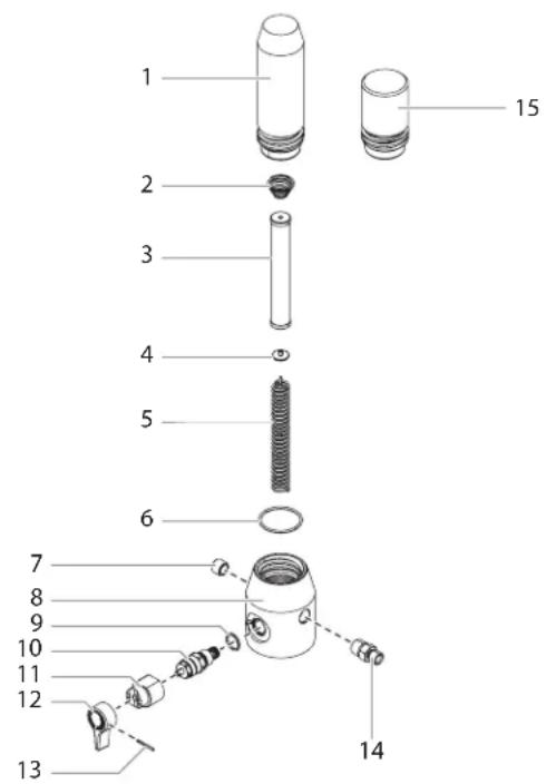
| # | PS 3.39 Berennung Description Désignation Denominazione | ||||
| 1 | 0524 918 | Filtergehäuse | Filter housing | Corps de filtre | Scatola del filtro |
| 2 | 14058 | Konusfeder | Conical spring | Ressort | Molla conica |
| 3 050 | 8 748 Filterpatrone | 60 Maschen(Standardausrüstung) | Filter, 60 mesh (standard) | Filtre, 60 mailles (standard) Filtro | 60 maglie (standard) |
| 0508 451 | Filterpatrone, 30 Maschen | Filter, 30 mesh | Filtre, 30 mailles | Filtro, 30 maglie | |
| 0508 452 | Filterpatrone, 100 Maschen | Filter, 100 mesh | Filtre, 100 mailles | Filtro, 100 maglie | |
| 4 | 0508 603 | Stützscheibe | Bearing ring | Rondelle | Rondella |
| 5 | 0508 749 | Stützfeder | Bearing spring | Ressort | Molla di spinta |
| 6 | 0551 951 | O-ring | O-ring | Joint torique | O-ring |
| 7 | 0507 739 | Rohrverschlussschraube | Pipe plug | Bouchon fileté | Tappo tubo |
| 8 | 0290 264 | Gehäuse | Housing | Logement | Alloggiamento |
| 9 | 0507 745 | Dichtungsring | Gasket | Joint | Guarnizione |
| 10 05 | 58 727 Baugruppe Bypass-Ventil(beinhaltet Pos. 9) | Bypass valve assembly(includes item 9) | Ensemble by-pass (comprendle élément Pos. 9) | Gruppo valvola di by-pass(comprende articoli 9) | |
| 11 | 0507 931 | Nockengrund | Cam base | Support de came | Base della camma |
| 12 | 0508 744 | Ventilschalter | Relief valve knob | Bouton du robinet | Impugnatura della valvola |
| 13 | 5006 543 | Kerbstift | Groove pin | Goupille cannelée | Perno scanalato |
| 14 | 0088 162 | Doppelstutzen | Fitting | Raccord double | Bocchettone doppio |
| 15 | 0558 668 | Filterkapsel | Filter plug | Bouchon-filtre | Tappo del filtro |
| 0507 254 Entlastungsventil mitHandgriff (beinhaltet Pos.9 – 13) | Relief valve w/ handle(includes items 9 – 13) | Vanne de décharge avecla poignée (comprend leséléments Pos. 9 à 13) | Valvola di sfiato con lamaniglia (comprende articoli9 – 13) | ||
d HoHeR WAGeN GB uPRIGHT cART ASSemBLy
F cHARIoT HAuT I cAReLLo ALTo
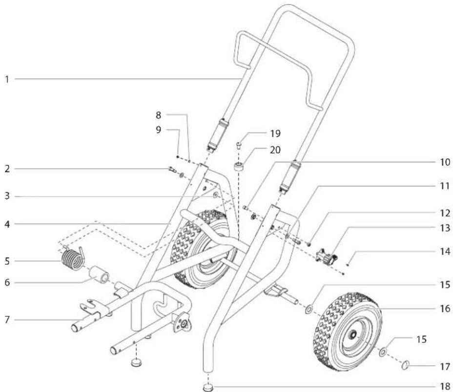
| # | PS 3.39 Berennung Description Désignation Denominazione | ||||
| 1 0290 | 296 Handgriff (inklusive der Elemente 8-9) | Handle assembly (includes items 8-9) | Poignée (comprend les éléments 8-9) | Impugnatura (comprende articoli n 8-9) | |
| 2 9805 | 352 Schraube (2) | Screw (2) Vis (2) Vite (2) | |||
| 3 0290 | 257 Buchse | Bushing | Bague | Boccola | |
| 4 | 805-200 | Grundgestell | Cart weldment | Chàssis de base | Telaio di base |
| 5 | 9894 275 | Stützfeder | Spring | Ressort | Molla |
| 6 | 0290 294 | Buchse | Sleeve | Douille | Bussola |
| 7 | 0290 285 | Baugruppe Wagen | Carriage assembly | Ensemble chariot | Gruppo di trasporto |
| 8 | 0509 386 | Scheibe (4) | Washer (4) | Rondelle (4) | Rondella (4) |
| 9 0295 | 608 Schraube (4) | Screw (4) Vis (4) Vite (4) | |||
| 10 0279 | 481 Schraube | Screw Vis | Vite | ||
| 11 | 9820 305 | Scheibe (2) | Washer (2) | Rondelle (2) | Rondella (2) |
| 12 | 0555 319 | Arretiermutter | Jam nut | Ecrou d'arrêt | Dado di arresto |
| 13 | 0290 236 | Baugruppe Nocken | Cam assembly | Ensemble came | Gruppo camma |
| 14 9805 | 353 Schraube (2) | Screw (2) Vis (2) Vite (2) | |||
| 15 | 0294 534 | Abstandhalter (4) | Spacer (4) | Entretoise (4) | Distanziatore (4) |
| 16 | 0509 624 | Rad (2) | Wheel (2) | Roue (2) | Ruota (2) |
| 17 | 800-019 | Radkappe (2) | Axle cap (2) | Chapeau de roue (2) | Coppa coprimozzo (2) |
| 18 | 9885 571 | Verschlussstopfen (2) | Plug (2) | Bouchon (2) | Tappo (2) |
| 19 | 54458 Schraube (2) | Screw (2) Vis (2) Vite (2) | |||
| 20 | 13538 | Fuß (2) | Pad (2) | Pied (2) | Piede (2) |
Division Professional Finishing
Otto Lilienthal Strasse 18
88677 Markdorf
As a result of an EC regulation being effective as from January 1, 1990, the manufacturer shall only be liable for his product if all parts come from him or are released by him, and if the devices are properly mounted and operated. If the user applies outside accessories and spare parts, the manufacturer's liability can fully or partially be inapplicable; in extreme cases usage of the entire device can be prohibited by the competent authorities (employer's liability insurance association and factory inspectorate division).
Only the usage of original WAGNER accessories and spare parts guarantees that all safety regulations are observed.
3+2 YEARS GUARANTEE FOR PROFESSIONAL FINISHING
Wagner professional guarantee
(Status 01.02.2009)
1. Scope of guarantee
All Wagner professional colour application devices (hereafter referred to as products) are carefully inspected, tested and are subject to strict checks under Wagner quality assurance. Wagner exclusively issues extended guarantees to commercial or professional users (hereafter referred to as "customer") who have purchased the product in an authorised specialist shop, and which relate to the products listed for that customer on the Internet under www.wagner-group.com/profi-guarantee.
The buyer's claim for liability for defects from the purchase agreement with the seller as well as statutory rights are not impaired by this guarantee.
We provide a guarantee in that we decide whether to replace or repair the product or individual parts, or take the device back and reimburse the purchase price. The costs for materials and working hours are our responsibility. Replaced products or parts become our property.
2. Guarantee period and registration
The guarantee period amounts to 36 months. For industrial use or equal wear, such as shift operations in particular, or in the event of rentals it amounts to 12 months.
Systems driven by petrol or air are also guaranteed for a 12 month period.
The guarantee period begins with the day of delivery by the authorised specialist shop. The date on the original purchase document is authoritative.
For all products bought in authorised specialist shops from 01.02.2009 the guarantee period is extended to 24 months providing the buyer of these devices registers in accordance with the following conditions within 4 weeks of the day of delivery by the authorised specialist shop.
Registration can be completed on the Internet under www.wagner-group.com/profi-guarantee. The guarantee certificate is valid as confirmation, as is the original purchase document that carries the date of the purchase. Registration is only possible if the buyer is in agreement with having the data being stored that is entered during registration.
When services are carried out under guarantee the guarantee period for the product is neither extended nor renewed.
Once the guarantee period has expired, claims made against the guarantee or from the guarantee can no longer be enforced.
3. Handling
If defects can be seen in the materials, processing or performance of the device during the guarantee period, guarantee claims must be made immediately, or at the latest within a period of 2 weeks.
The authorised specialist shop that delivered the device is entitled to accept guarantee claims. Guarantee claims may also be made to the service centres named in our operating instructions. The product has to be sent without charge or presented together with the original purchase document that includes details of the purchase date and the name of the product. In order to claim for an extension to the guarantee, the guarantee certificate must be included.
The costs as well as the risk of loss or damage to the product in transit or by the centre that accepts the guarantee claims or who delivers the repaired product, are the responsibility of the customer.
4. Exclusion of guarantee
Guarantee claims cannot be considered
- for parts that are subject to wear and tear due to use or other natural wear and tear, as well as defects in the product that are a result of natural wear and tear, or wear and tear due to use. This includes in particular cables, valves, packaging, jets, cylinders, pistons, means-carrying housing components, filters, pipes, seals, rotors, stators, etc. Damage due to wear and tear that is caused in particular by sanded coating materials, such as dispersions, plaster, putty, adhesives, glazes, quartz foundation.
- in the event of errors in devices that are due to non-compliance with the operating instructions, unsuitable or unprofessional use, incorrect assembly and/or commissioning by the buyer or by a third party, or utilisation other than is intended, abnormal ambient conditions, unsuitable coating materials, unsuitable operating conditions, operation with the incorrect mains voltage supply/frequency, over-operation or defective servicing or care and/or cleaning.
- for errors in the device that have been caused by using accessory parts, additional components or spare parts that are not original Wagner parts.
- for products to which modifications or additions have been carried out.
- for products where the serial number has been removed or is illegible
- for products to which attempts at repairs have been carried out by unauthorised persons.
- for products with slight deviations from the target properties, which are negligible with regard to the value and usability of the device.
- for products that have been partially or fully taken apart.
5. Additional regulations.
The above guarantees apply exclusively to products that have been bought by authorised specialist shops in the EU, CIS, Australia and are used within the reference country.
If the check shows that the case is not a guarantee case, repairs are carried out at the expense of the buyer.
The above regulations manage the legal relationship to us concludingly. Additional claims, in particular for damages and losses of any type, which occur as a result of the product or its use, are excluded from the product liability act except with regard to the area of application.
Claims for liability for defects to the specialist trader remain unaffected.
German law applies to this guarantee. The contractual language is German. In the event that the meaning of the German and a foreign text of this guarantee deviate from one another, the meaning of the German text has priority.
J. Wagner GmbH
Division Professional Finishing
Otto Lilienthal Strasse 18
88677 Markdorf
Federal Republic of Germany
NOTE IMPORTANTE SUR LA RESPONSABILITÉ DE PRODUIT
Division Professional Finishing
Otto Lilienthal Strasse 18
88677 Markdorf
Division Professional Finishing
Otto Lilienthal Strasse 18
88677 Markdorf
In observance of the European Directive 2002/96/EC on waste electrical and electronic equipment and implementation in accordance with national law, this product is not to be disposed of together with household waste material but must be recycled in an environmentally friendly way!

Wagner or one of our dealers will take back your used Wagner waste electrical or electronic equipment and will dispose of it for you in an environmentally friendly way. Please ask your local Wagner service centre or dealer for details or contact us direct.
- F -
T el. 0 50 32-8 00 06 23
Telefax 0 50 32-8 00 06 24
München
Jahnke GmbH
Hochstraße 7
82024 Taufkirchen
Tel. 0 89 /6 14 00 22
Telefax 0 89 / 6 14 04 33
email: info@airless.de
www.airless.de
Nürnberg
Grimmer GmbH
Starenweg 28
91126 Schwabach
Tel. 0 91 22 / 7 94 73
Telefax 0 91 22 / 7 94 75 0
email: info@grimmer-sc.de
www.grimmer-sc.de
Markdorf - Zentrale
J. WAGNER GmbH
GB Wagner Spraytech (UK) Limited
The Coach House
2 Main Road
Middleton Cheney OX17 2ND
Great Britain
UK-Helpline 01295 714200
Fax 01295 710100
enquiries@wagnerspraytech.co.uk
B WSB Finishing Equipment
Veilinglaan 56-58
1861 Meise-Wolvertem
Belgium
Tel. +32/2/269 46 75
Telefax +32/2/269 78 45
info@wagner-wsb.nl
NL WSB Finishing Equipment BV
De Heldinnenlaan 200,
3543 MB Utrecht
Netherlands
Tel. +31/ 30/241 41 55
Telefax +31/ 30/241 17 87
info@wagner-wsb.nl
d J. Wagner GmbH
Telefax 04.42.53.44.36

- PROSPRAY 3.39
- Warnung!
- GeFAHR: HocHdRucKScHLAucH
- GeFAHR: exPLoSloNS- uNd BRANdGeFAHR
- TRANSPORT
- TRANSPORT IM FAHRZEUG
- ReINIGuNG deR AIRLeSS-SPRITzPISToLe
- eIN- uNd AuSLASSVeNTIL
- PUMP-RUNNER
- (Best. Nr. 2306987)
- Be safety conscious!
- SAFeTy ReGuLATIoNS FoR AIRLeSS SPRAyING 36
- GeNeRAL Vl eW oF APPLlcATIoN 41
- deScRIPTIoN oF uNIT 42
- STARTING oPeRATIoN 45
- SPRAyING TecHNIque 50
- HANdLING THE HIGH-PReSSuRe HoSe \_\_\_\_ 51
- INTeRRuPTIoN oF WoWK 51
- cLeANING THE uNIT (SHuTTING doWN) \_ 52
- Remedy IN cASe of FAuLTS 54
- SeRVlcING 55
- RePAIRS AT THE uNIT 55
- APPeNdIx 61
- AcceSSoRleS FoR PRoSPRAy 3.39 \_\_\_\_ 130/131
- ImPoRTANT NoTeS oN PROducT LIABILITY \_141
- 3+2 yeARS GuARANTee FoR PRoFeSSIoNAL
- FINISHING 141
- SALeS AND SeRVIce comPANleS 147/148
- SAFeTy ReGuLATIoNS FoR AIRLeSS SPRAyING
- exPLANATIoN oF SymBoLS uSed
- HAzARd: INJecTloN INJuRy
- PReVeNTIoN:
- HAzARd: HIGH PReSSuRe HoSe
- HAzARd: exPLoSloN oR FIRe
- HAzARd: HAzARdouS VAPoRS
- HAzARd: GeNeRAL
- eLecTRIc SAFeTy
- WoRK oR RePAIRS AT THE eLecTRIcAL equIPmeNT:
- eLecTRoSTATIC cHARGING (FoRmATIoN of SPARKS or FLAmeS)
- GENERAL VIEW OF APPLICATION
- APPLICATION
- COATING MATERIALS
- PROCESSIBLE COATING MATERIALS
- FILTERING
- VISCOSITY
- TWO-COMPONENT COATING MATERIAL
- COATING MATERIALS WITH SHARP-EDGED ADDITIONAL MATERIALS
- DESCRIPTION OF UNIT
- AIRLESS PROCESS
- FUNCTIONING OF THE UNIT
- LeGeNd FoR exPLANAToRy dIAGRAM PRoSPRAy 3.39
- exPLANAToRy dIAGRAM PS 3.39
- TRANSPORTATION
- Pushing or pulling the unit
- TRANSPORTATION IN VEHICLE
- PAINT MATERIAL SETUP
- TEXTURED MATERIAL SETUP
- CONTROL PANEL INDICATORS
- SERVICE INDICATOR
- PRESSURE INDICATOR
- Blinking Yellow
- Solid Yellow
- Solid Green
- PRESSURE CONTROL KNOB SETTINGS
- CONNECTION TO THE MAINS NETWORK
- CLEANING PRESERVING AGENT WHEN STARTING-UP OF OPERATION INITIALLY
- TAKING THE UNIT INTO OPERATION WITH COATING MATERIAL
- DIGITAL ELECTRONIC SPRAY CONTROL (DESC)
- FUNCTION KEYS
- MENU SCREENS
- MAIN SCREEN
- VOLUME PUMPED SCREEN
- JOB VOLUME SCREEN
- UNIT SERIAL # SCREEN
- TIMERS SCREEN
- JOB TIMERS SCREEN
- SERVICE TIME SCREEN
- SECURITY CODE SCREEN
- PRIme ScReeN
- RAPId cLeAN ScReeN
- SPRAyING
- HANdLING The HIGH-PReSSuRe HoSe
- INTeRRuPTIoN oF WoRK
- CLEANING THE UNIT (SHUTTING DOWN)
- CLEANING UNIT FROM OUTSIDE
- CLEANING THE INLET SCREEN
- cLeANING THE HIGH-PReSSuRe FILTeR
- cLeANING AIRLeSS SPRAy GuN
- INTAKe FILTeR IN AIRLeSS SPRAy GuN (FIG. 11)
- SeRVIcING
- GeNeRAL SeRVIcING
- HIGH-PReSSuRe HoSe
- RePAIRS AT THE uNIT
- ReLleF VALVe
- INLeT AND ouTLeT VALVe
- PAcKINGS
- dIGITAL eLecTRoNlc SPRAy coNTRoL (deSc) eRRoR meSSAGeS
- cHecK TRANSduceR ScReeN
- cHecK PoTeNTlomeTeR ScReeN
- cHecK moToR ScReeN
- LoW VoLTAGe ScReeN
- HIGH moToR TemPeRATuRe ScReeN
- HIGH mecHANlcAL LoAd
- HIGH coNTRoL TemPeRATuRe ScReeN
- BAd HALL cycLe PoWeR ScReeN
- APPENDIX
- SELECTION OF TIP
- SOME RULES FOR THIS:
- SERVICING AND CLEANING OF AIRLESS HARD-METAL TIPS
- STANDARD TIPS
- The following points must be observed to keep the tip clean and ready for use:
- SPRAY GUN ACCESSORIES
- Tip extension with slewable knee joint (without tip)
- Tip extension
- AIRLESS TIP TABLE
- TEMPSPRAY
- Advantages:
- (Order No. 2306987)
- Features:
- Attention!
- TRANSPORT PAR VÉHICULE
- VOYANTS DU PANNEAU DE COMMANDES
- MISE EN SERVICE DU MATÉRIEL AVEC LE PRODUIT DE REVÊTEMENT
- NeTToyAGe du PISToLeT AIRLeSS
- cLAPeT d'AdmISSIoN eT de ReFouLemeNT
- CHOIX DES BUSES
- (Réf. No. 2306987)
- Avvertenza!
- TRASPORTO
- TRASPORTO CON UN VEICOLO
- INDICATORI DEL PANNELLO DI CONTROLLO
- MESSA IN SERVIZIO DELL'APPARECCHIO CON MATERIALE DI COPERTURA
- VIDEATA TIMERS (TEMPORIZZATORI)
- VIdeATA PRIme (INNeSco PomPA)
- PuLizIA deLL'AeRoGRAFo AIRLeSS
- (N° ord. 2306987)
- Division Professional Finishing
- Otto Lilienthal Strasse 18
- Markdorf
- 3+2 YEARS GUARANTEE FOR PROFESSIONAL FINISHING
- Scope of guarantee
- Guarantee period and registration
- Handling
- Exclusion of guarantee
- Additional regulations.
- Wagner GmbH
- NOTE IMPORTANTE SUR LA RESPONSABILITÉ DE PRODUIT
- - F -
- München
- Nürnberg
- Markdorf - Zentrale
Brand : WAGNER
Model : ProSpray 3.39
Category : Paint gun