USER MANUAL SHAZA 22.2 A1 SILVERCREST
CORDLESS CYCLONE HANDHELD VACUUM CLEANER AQUA / HANDSTAUBSAUGER AKKU ZYKLON AQUA ASPIRATEUR CYCLONIQUE SANS FIL AQUA SHAZA 22.2 A1
GB IE
CORDLESS CYCLONE HANDHELD VACUUM CLEANER AQUA
Operating instructions
FR BE
ASPIRATEUR CYCLONIQUE SANS FIL AQUA
Mode d'emploi
CZ
AKU RUČNÍ CYKLONOVÝ VYSAVAČ AQUA
Návod k obsluze
SK
AKU TYČOVÝ CYKLÓNOVÝ VYSÁVAČ AQUA
Návod na obsluhu
DK
HÅNDST∅VSUGER CYKLON MED GENOPLADELIGT BATTERI AQUA
Before reading, unfold the page containing the illustrations and familiarise yourself with all functions of the device.
DE AT CH
GB/IE Operating instructions Page 1
Contents
Introduction 2
Intended use 2
Warnings and symbols used 2
Important safety instructions....3
Package contents and transport inspection....6
Appliance description....6
Technical data....7
Before first use ....8
Setting up the appliance 8
Mounting the wall bracket and accessories holder 8
Getting started 9
Information about the battery 9
Charging the battery 9
Operation and use 10
Switching the appliance on 10
Selecting an operating mode 11
Dismantling the appliance .... 1 1
Using the accessories 12
Using the mop attachment 13
After use....14
Cleaning 14
Emptying the dirt container and cleaning the filter 14
Cleaning the rotary brush 17
Cleaning the appliance 17
Storage 18
Disposal....18
Disposal of the appliance 18
Disposal of the packaging 18
Disposal of batteries 19
Ordering replacement parts 19
Kompernass Handels GmbH warranty 19
Service 20
Importer 20
Introduction
Congratulations on the purchase of your new appliance. You have selected a high-quality product.

The operating instructions are part of this product. They contain important information about safety, usage and disposal. Before using the product, please familiarise yourself with all operating and safety instructions. Use the product only as described and for the specified range of applications. Please also pass on all documents to any future owner.
Intended use
The appliance may only be used for cleaning dry or wet surfaces and for vacuuming dry or wet material. Do not vacuum people or animals with this appliance. Any other usage or modification of the appliance is deemed to be improper and carries a significant risk of accidents. The manufacturer accepts no liability for damages caused by improper use or incorrect operation of the appliance. The appliance is not intended for commercial use.
Warnings and symbols used
The following warnings and symbols are used in these operating instructions, on the packaging and on the appliance (where applicable):
 | DANGER! A warning with this symbol and the signal word "DANGER" indicates an imminently hazardous situation which will result in death or serious injury if not avoided. |
 | WARNING! A warning with this symbol and the signal word "WARNING" indicates a potentially hazardous situation which could result in death or serious injury if not avoided. |
 | CAUTION! A warning with this symbol and the signal word "CAUTION" indicates a potentially hazardous situation which could result in a minor or moderate injury if not avoided. |
 | ATTENTION! A warning with this symbol and the signal word "ATTENTION" indicates a potential situation which could result in property damage if not avoided. |
 | Note: A note provides additional information that will assist you in using the appliance. |
| --- | DC current/voltage |
| ~ | AC current/voltage |
 | Observe the operating instructions |
Important safety instructions

■ Check the appliance for visible external damage before use. Do not operate an appliance that has been damaged or dropped.
■ Do not use the mains adapter if it has a damaged plug or cable.
■ The mains adapter and the permanently affixed connection cable may not be repaired. In the event of a defect, the entire mains adapter must be replaced with another of identical design.
■ To prevent accidents, have defective plugs and/or power cables replaced immediately by an authorised specialist, our Customer Service or a similarly qualified person.
■ Have all repairs carried out by a specialist workshop. Under no circumstances should you open the appliance yourself.
Repairs that are not carried out by a specialist workshop could lead to physical injuries.
■ Before switching on the appliance, make sure that the mains voltage corresponds to the voltage indicated in the technical data for the appliance.
■ Never touch the mains adapter or the appliance with wet or damp hands.
■ Do not use the mains adapter with an extension cable; connect the mains adapter directly to a power socket.

Do not charge or use the appliance outdoors.
⚠ WARNING! RISK OF INJURY!
■ Do not change any accessories while the appliance is switched on.
■ Do not use the vacuum cleaner for vacuuming up sharp objects or glass shards.
■ Do not use the vacuum cleaner for vacuuming up burning matches, glowing embers or cigarette butts.
■ Do not use the vacuum cleaner for vacuuming up chemical products, stone dust, gypsum, cement or similar particles.
■ This appliance is not suitable for use with inflammable and explosive substances or chemical and aggressive liquids.
■ Always store the appliance indoors. To prevent accidents, keep the appliance in a dry location when not in use.
■ Under extreme conditions, leaks in the battery cells may occur. In the event that battery fluid comes into contact with skin or eyes, the affected area must be rinsed off with water immediately. Contact a physician.
This appliance may be used by children aged 8 years and above and by persons with limited physical, sensory or mental capabilities or lack of experience and knowledge, provided that they are under supervision or have been told how to use the appliance safely and are aware of the potential risks.
■ Do not allow children to play with the appliance. Cleaning and user maintenance tasks may not be carried out by children unless they are supervised.
■ Take special care when using the vacuum cleaner on stairs.
! ATTENTION! PROPERTY DAMAGE!
■ Use only accessories recommended by the manufacturer.
■ The mains adapter may not be used for other purposes. Never carry the wall bracket or the mains adapter by the cable. Do not pull on the cable when you want to move the appliance.
■ Always grip the power plug to disconnect the appliance from the power supply.
■ Always be sure to keep the vacuum cleaner away from heating elements, ovens or other heated appliances and surfaces.
■ Make sure that the ventilation slits are never obstructed.
A blocked ventilation circuit can result in overheating and damage to the appliance.

The product is equipped or supplied with a lithium-ion battery. Do not throw the rechargeable battery into a fire and do not subject it to high temperatures. There is a risk of an explosion!
■ Do not use the vacuum cleaner without the EPA filter inserted.
■ Do not use the mains adapter for a different product and do not attempt to charge this appliance with a different mains adapter. Use only the mains adapter supplied with this appliance (model SHAZ 22.2 F7-1).
■ Never store the device when it is discharged. Prolonged storage in a discharged state can cause permanent damage to the battery. If the device is stored for a longer period of time, the charge level of the battery must be checked regularly. The optimum charge level is between 50% and 80%.
Package contents and transport inspection
1) Remove all parts of the appliance and the operating instructions from the packaging.
2) Remove all packaging materials and any films and labels.
The package contents include the following components (see fold-out page for illustrations):
- Cordless cyclone vacuum cleaner
- Suction pipe
- Floor brush
- Crevice nozzle
- Round brush nozzle (with brush attachment)
• 2-in-1 combination brush
- Mop attachment
- 2 mop pads
- Wall bracket
- Accessories holder
• Installation materials (4 screws, 4 wall plugs)
- Mains adapter
- Replaceable battery
- Operating instructions
i Note
▶ Check the package for completeness and signs of visible damage.
If any items are missing or damaged as a result of defective packaging or transportation, please contact the Service Hotline (see section Service).
Appliance description (See fold-out page for illustrations)
① Battery release button
② Replaceable battery
③ Charging socket
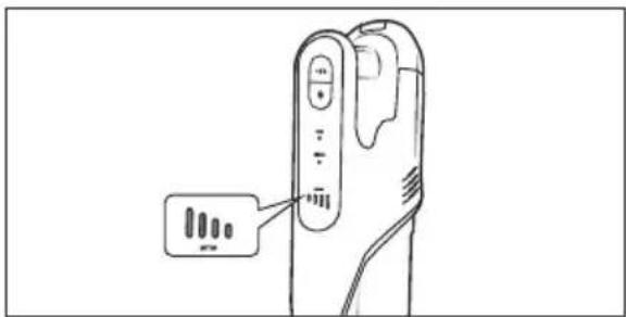
④ Ventilation slits
⑤ EPA filter
6 Stainless steel filter
⑦ Dirt container
8 Release button for dirt container
9 Dirt container lid
10 Mains adapter
⑪ Barrel plug
12 2-in-1 combination brush
13 Crevice nozzle
14 Round brush nozzle (with brush attachment)
15 Screws
16 Wall plug
⑰ Accessories holder
18 Wall bracket
19 Rotary brush release
20 Rotary brush holder
21 Rotary brush
22 Floor brush
23 Floor brush release button
24 Suction pipe
25 Suction pipe release button
26 Operating mode
27 Battery indicator
28 Display panel (battery indicator/operating mode)
29 On/Off switch
30 Operating mode button +/- (Eco/Boost)
31 Mop attachment
32 Fresh water tank
33 Closing tab
34 Mop pad
Technical data
| Appliance |
| Input voltage 26 V | —— |
| Input current 0.45 A | |
| Power consumption 130 W | |
| Polarity | 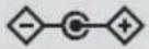 |
| Batteries |
| Capacity 2500 mAh | |
| Battery | 22.2 V---(6 x 3.7 V lithium-ion batteries) |
| Running time on a full battery charge using the floor nozzle (with mop attachment) | Eco: approx. 45 minutes (approx. 38 minutes)Boost: approx. 25 minutes (approx. 20 minutes) |
| Mains adapter |
| Manufacturer | KOMPERNASS HANDELS GMBH, BURGSTRASSE 21, 44867 BOCHUM, GERMANY Registered court: AG Bochum Register number: HRB 4598 |
| Model SHAZ 22.2 F7-1 | |
| Input voltage | 100-240 V ~ |
| Input AC frequency | 50/60 Hz |
| Output voltage | 26.0 V --- |
| Output current | 0.45 A |
| Output power | 11.7 W |
| Average efficiency in operation | 85.0% |
| Efficiency at low load (10%) | 80.5% |
| Power consumption at no load | 0.07 W |
| Input current | 0.4 A |
| Polarity | |
| Protection class | II/□double insulation) |
| Efficiency class | 6 VI |
i Note
▶ No user action is required to switch the product between 50 and 60 Hz. The product switches automatically to either 50 or 60 Hz.
Before first use
Setting up the appliance
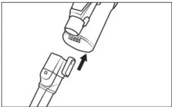
1) Push the suction pipe 24 onto the appliance until it audibly clicks into place (see Fig. 1).
natural_image
Diagram showing two mechanical components with an arrow indicating a process or transformation (no text or symbols present)
Fig. 1
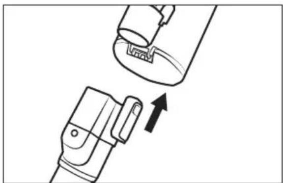
2) Push the suction pipe ②4 into the floor brush ②2 until it audibly clicks into place (see Fig. 2).
natural_image
Illustration of a hand holding a mechanical device with an arrow indicating process (no text or symbols)
Fig. 2
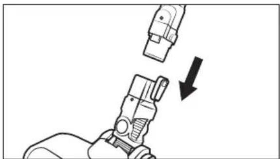
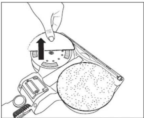
3) Push the battery ② into the appliance until it audibly clicks into place (see Fig. 3).
natural_image
Line drawing of a hand tool and a small device with a label, showing no text or symbols on the devices themselves.
Fig. 3
Mounting the wall bracket and accessories holder
DANGER!
▶ Ensure that there are no power cables or other conduits or pipes in the wall at the location where you intend to bore the holes for the wall bracket ⑱. Drilling into a current-carrying electric cable can be potentially fatal!
1) Insert the barrel plug ⑪ of the mains adapter ⑩ into the wall bracket ⑱ (see Fig. 4). Secure the barrel plug ⑪ by turning it.
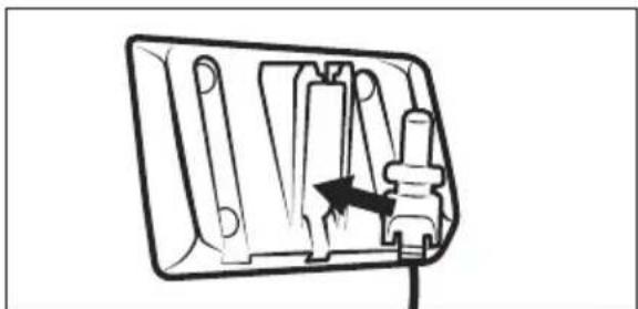
natural_image
Diagram of a mechanical switch or socket assembly with internal components and an arrow indicating direction (no text or symbols)
Fig. 4
2) Find a suitable mounting location for the wall bracket 18:
- The wall bracket 18 must be mounted with sufficient distance to the floor to ensure easy insertion and removal of the appliance from the wall bracket 18.
- A mains socket must be accessible for the mains adapter 10.
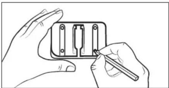
3) Use the wall bracket 18 to mark the four drill holes on the wall (see Fig. 5).
natural_image
Illustration of hands installing or adjusting a component with a tool (no text or symbols visible)
Fig. 5
4) Drill the marked holes with a 5-mm drill.
5) Push the supplied wall plugs 16 into the holes.
6) Screw the wall bracket 18 in place using the screws 15 provided.
7) Connect the mains adapter 10 to a mains socket.
Getting started
The vacuum cleaner is powered by a rechargeable, replaceable lithium-ion battery. Before using the vacuum cleaner for the first time, the battery ② must be charged for around 6 hours.
To care for the battery ^2 , we recommend the following:
Disconnect the mains adapter 10 from the mains socket after the battery 2 is charged.
i Note
The appliance is equipped with a temperature monitor to protect the battery ②.
At high ambient temperatures, the charging process may be interrupted or the appliance may switch off automatically in rare cases:
- The battery indicator ^27 flashes at one second intervals during charging. Charging is interrupted and automatically resumed as soon as the temperature of the appliance has dropped.
- The battery indicator 27 flashes five times at one second intervals during operation. The appliance switches off automatically. Allow the appliance to cool down for about 20–30 minutes before switching it on again.
Charging the battery
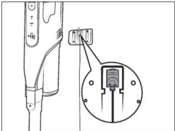
Place the vacuum cleaner in the wall bracket ⑬ from above so that the barrel plug ⑪ slips into the charging socket ③ on the bottom of the appliance.
The battery indicator 27 starts flashing and the charging process starts (see Fig. 6 and 7).
natural_image
Technical line drawing of a device with an inset showing a close-up of a mechanical component (no text or symbols)
Fig. 6

Fig. 7
When charging is complete, which can take about 6 hours if the battery ② is completely discharged, the battery indicator ⑳ lights up.
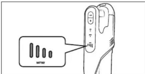
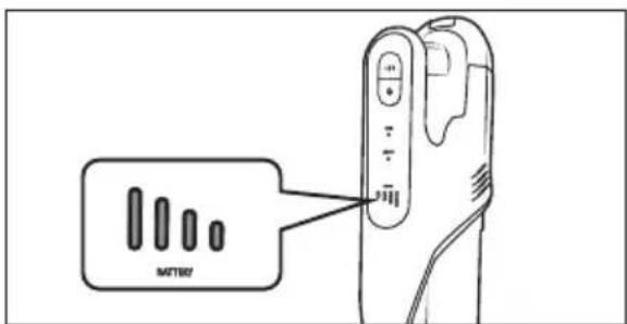
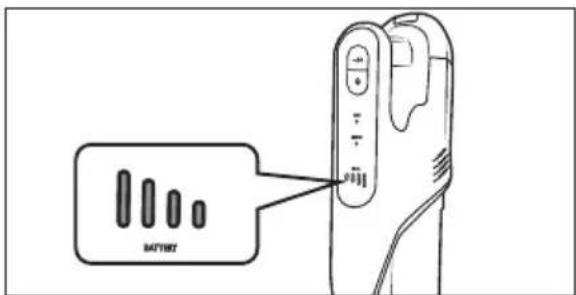
Battery indicators
The display panel 28 features five different battery indicators 27 to show the actual charging status of the battery 2:
The battery is fully charged.
The battery is charged to approx. 50%.
The battery is charged to approx. 25%.
The battery has only a small amount of charge left.
0000 The battery is empty.
i Note
▶ Recharge the battery ^2 as soon as the battery indicator ^28 shows a low remaining charge of the battery ^2 .
The appliance switches off shortly after an empty battery ② is displayed.
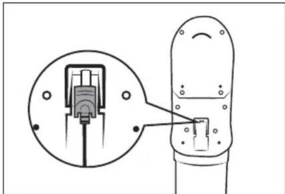
The vacuum cleaner can also be charged directly via the mains adapter 10. To do this, remove the barrel plug 11 from the wall bracket 18 by turning it slightly and insert it into the charging socket 3 on the appliance (see Fig. 8).
natural_image
Diagram of a mechanical component with an inset close-up showing internal structure (no text or symbols)
Fig. 8
Operation and use
! ATTENTION!
The suction openings of the appliance and the floor brush 22 and the suction pipe 24 must be free at all times and must not be blocked. Blockages lead to overheating and damage to the motor.
▶ Make certain that the EPA dust filter ⑤ is always inserted before using the appliance.
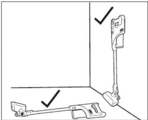
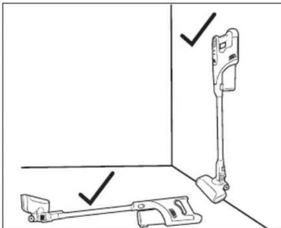
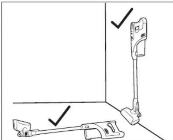
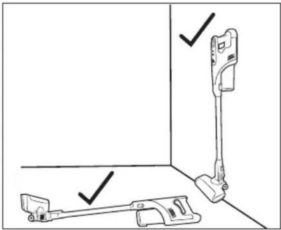
▶ Do not try to place the vacuum cleaner upright when you want to put it down or take it out of your hand in the meantime. To do this, place the vacuum cleaner in the wall bracket 18 or lay it on the floor (see Fig. 9 and 10). Due to its high centre of gravity, the vacuum cleaner may otherwise tip over and be damaged and possibly damage other objects when tipping over.
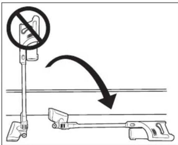
Fig. 9

natural_image
Technical line drawing of a vacuum cleaner with mounting bracket and handle (no text or symbols)
Fig. 10
Switching the appliance on
1) Remove the vacuum cleaner from the wall bracket ⑱. When you are not using the wall bracket ⑱, pull the barrel plug ⑪ out of the charging socket ③ on the underside of the appliance.
2) Press the On/Off switch ⏻ 29 to switch on the appliance. The display panel 28 shows the battery indicator 27 and operating mode 26 (Eco/Boost).
(i) Note
The appliance always starts in operating mode Eco after being switched on.
Selecting an operating mode
i Note
▶ To mop floors, see section Using the mop attachment.
The appliance has two different operating modes, each of which differs in terms of suction power and running time. Press the +/- 30 button to select the operating mode:
Eco
-For vacuuming hard floors, delicate carpets and rugs with low to medium soiling.
—The appliance consumes less battery power and the running time is therefore longer.
- Running time with fully charged battery approx. 45 minutes (with floor brush)/approx. 38 minutes (with mop attachment).
Boost
-For vacuuming hard floors and carpeting with heavy soiling
—Due to the high suction power, the best suction result is achieved with a short running time.
- Running time with fully charged battery approx. 25 minutes (with floor brush)/approx. 20 minutes (with mop attachment).
Dismantling the appliance
Suction pipe
To remove the suction pip ^24 from the appliance, hold down the suction pipe release button ^25 and pull the suction pipe ^24 off the suction opening of the appliance (see Fig. 11).
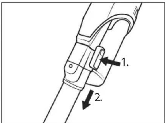
Fig. 11
Floor brush
To remove the floor brush ^22 from the suction pipe ^24 , hold down the floor brush release button ^23 and pull the suction pipe ^24 off the floor brush ^22 (see Fig. 12).
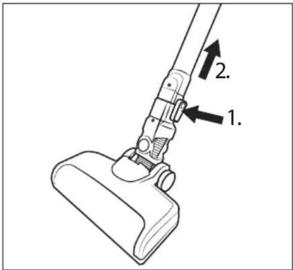
Fig. 12
Battery
To remove the battery 2 from the appliance, press and hold the battery release button 1 and pull the battery 2 out of the appliance (see Fig. 13).
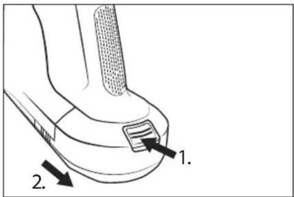
Fig. 13
Using the accessories
i Note
Before using an accessory, you must remove the floor brush 22. To remove the floor brush 22, see section Dismantling the appliance.
▶ You can use the accessories with or without the suction pipe 24 as required. To remove the suction pipe 24, see section Dismantling the appliance.
The package contents include three different nozzles/brushes for different areas of application as accessories:
Crevice nozzle
- Use the crevice nozzle ^13 to clean narrow, hard-to-reach places such as joints or corners.
2-in-1 combination brush
- The 2-in-1 combination brush ^12 can be used as a wide nozzle or as a brush. Press and hold the release button and slide the brush attachment forward or backward as needed. Use the 2-in-1 combination brush ^12 to vacuum drawers or storage compartments, for example, or to dust keyboards or delicate surfaces with the soft brush attachment.
Round brush nozzle (with brush attachment)
- Use the round brush nozzle ^14 with its hard bristles for deep-seated dirt on coarse carpets or heavily soiled car interiors. The brush attachment can be removed from the nozzle to vacuum rounded inserts or storage compartments in the car, for example.
- Push the accessory onto the suction pipe 24 or onto the suction opening of the appliance until it clicks into place (see Fig. 14). Make sure that the locking mechanism is in the correct position.
natural_image
Technical line drawing of a mechanical component with an arrow indicating assembly or motion (no text or symbols)
Fig. 14
To remove the accessory, press and hold the release button on the accessory, then pull the accessory off the suction pipe 24 or the suction opening of the appliance (see Fig. 15).
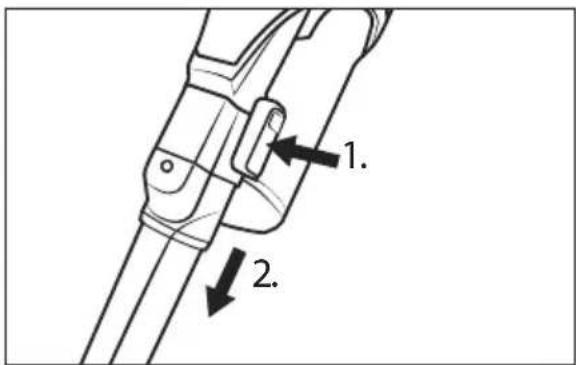
Fig. 15
Using the mop attachment
CAUTION!
▶ Fill the fresh water tap only with cold to warm tap water (up to max. 60°C) or distilled water. Do not use boiling water.
▶ Use only standard commercial, non-foaming floor cleaners as cleaning additives.
(i) Note
▶ After you have used the mop attachment ③1, clean the dirt container ⑦ immediately. Otherwise, bacteria or mould will build up inside! Make sure that the EPA filter ⑤ is completely dry before using the appliance again.
◆ Use the mop attachment to mop floors.
Remove the floor brush and fit the mop attachment on the suction pipe (see section Dismantling the appliance).
Filling the fresh water tank
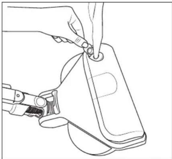
1) Grip the closing tab 33 of the fresh water tank 32 with your fingers and pull it upwards out of the filler opening of the fresh water tank 32 (see Fig. 16).
natural_image
Line drawing of a hand using a tool to adjust or install a device (no text or symbols present)
Fig. 16
2) Fill the fresh water tank ③2 with tap water or distilled water (see Fig. 16).
3) Close the filler opening of the fresh water tank ③2 again by pressing the closing tab ③3 firmly into the filler opening.
Attaching/removing the mop pads
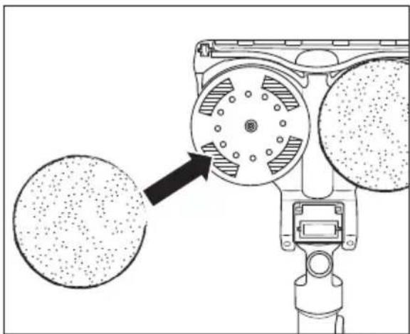
To fit a mop pad 34 to the mop attachment 31, place it centrally on one of the two rotating plates on the underside of the mop attachment 31 (see Fig. 17). Then press it firmly onto the hook and loop strips of the rotating plate.
natural_image
Technical diagram of a mechanical device with two circular components and a central rotating wheel (no text or symbols)
Fig. 17
To remove a mop pad from the mop attachment 31, grip it with your fingers and pull it upwards off the mop attachment 31 (see Fig. 18).
natural_image
Illustration of a hand using a tool to adjust a circular component, with no visible text or symbols.
Fig. 18
(i) Note
▶ Before use, moisten the mop pads ^54 a little so that they can absorb the dirt better.
▶ Clean the mop pad 34 under warm water. If necessary, add some cleaning agent to the mop pads 34. Follow the care instructions on the care label:

Hand wash up to 40°C

Do not bleach

Do not tumble dry

Do not iron

Do not dry clean
▶ Allow the mop pad 34 to dry completely before using them again.
After use
After use, press the On/Off switch ⏻ 29 to switch off the appliance. The display panel 28 goes out.
- Attach the accessories hold to the suction pipe (see Fig. 19).
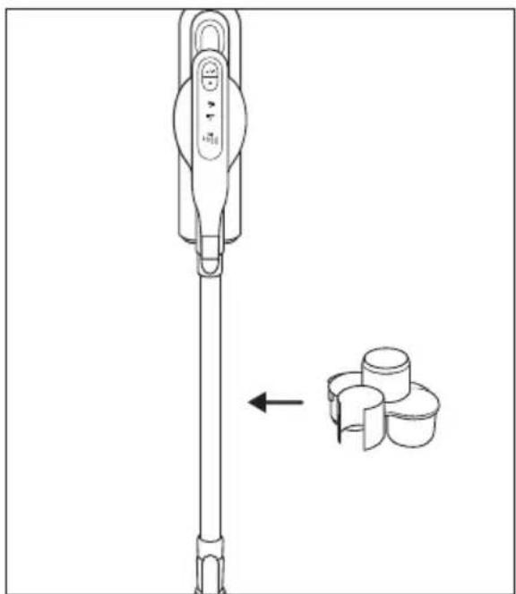
natural_image
Technical line drawing of a mechanical device with a separate inset showing three cylindrical components (no text or symbols)
Fig. 19
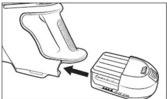
Remove accessories from the appliance and place them on the accessories holder 17 for storage (see Fig. 20).
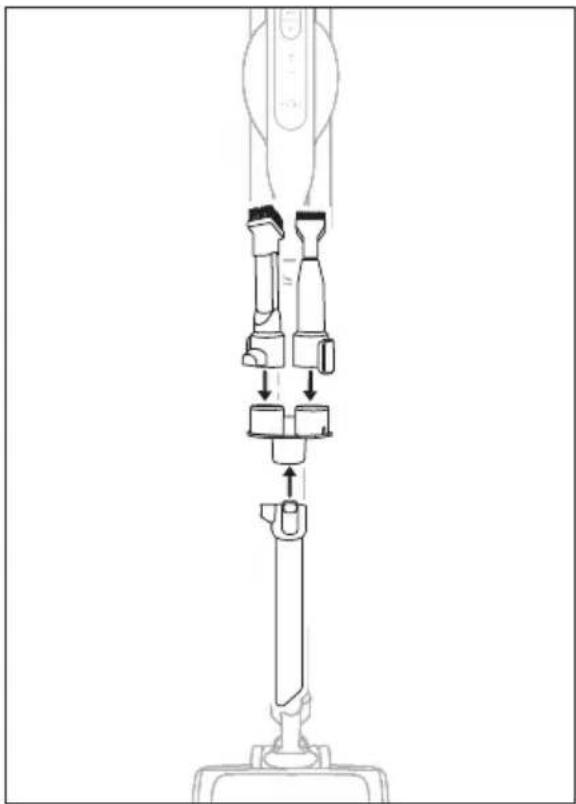
natural_image
Technical line drawing of a mechanical device with multiple ports and a central shaft (no text or symbols)
Fig. 20
Place the vacuum cleaner in the wall bracket 18. Start charging when the battery 2 has only a small amount of charge left
Cleaning

WARNING!
▶ Always switch off the appliance before cleaning it.
Emptying the dirt container and cleaning the filter
(i) Note
▶ Empty the dirt container ⑦ and clean the stainless steel filter ⑥ and the EPA filter ⑤ when the dirt container ⑦ level reaches the MAX mark.
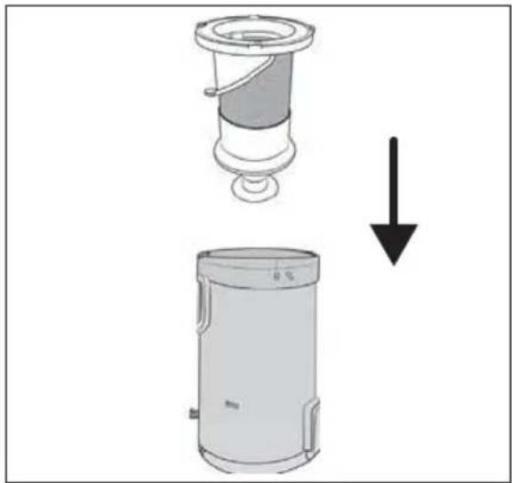
1) Hold the dirt container ⑦ in a waste bin and press the release button for the dirt container lid ⑧. The dirt container lid ⑨ opens and the contents are emptied into the waste bin (see Fig. 21). Then close the dirt container lid ⑨.
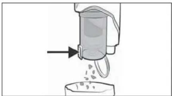
natural_image
Diagram of a chemical reactor with liquid being poured into a container (no text or labels)
Fig. 21
2) To remove the dirt container ⑦ from the appliance, turn it towards the symbol 📋 (open) until it can be detached from the appliance (see Fig. 22).
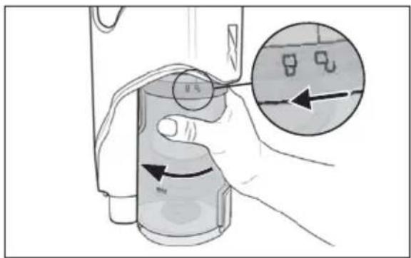
Fig. 22
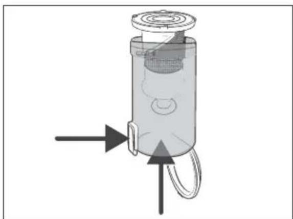
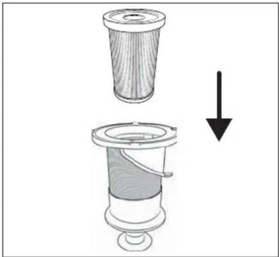
3) Remove the stainless steel filter ⑥ from the dirt container ⑦ by pressing the dirt container lid release button ⑧. Then slide the stainless steel filter ⑥ out of the dirt container ⑦ from below (see Fig. 23).
natural_image
Diagram of a cylindrical device with internal components and directional arrows, no visible text or symbols
Fig. 23
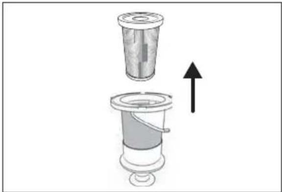
4) Remove the EPA filter 5 from the stainless steel filter 6 by reaching into the opening of the EPA filter 5 and pulling it out of the stainless steel filter 6 (see Fig. 24).
natural_image
Diagram of a mechanical device with a cylindrical component and an ascending arrow, no text or symbols present
Fig. 24
5) Rinse the EPA filter ⑤ and the stainless steel filter ⑥ under cold or lukewarm water. Allow the EPA filter ⑤ and stainless steel filter ⑥ to air dry completely before putting them back into the dirt container ⑦ (see Fig. 25).
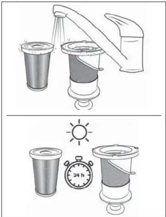
Fig. 25
(i) Note
▶ When cleaning the stainless steel filte ^6 , take care not to lose the rubber supports on the lower opening.
6) Insert the stainless steel filter ⑥ into the dirt container ⑦ and push it all the way down (see Fig. 26). Pay attention to the different sized locks on the stainless steel filter ⑥. The stainless steel filter ⑥ can only be inserted into the dirt container ⑦ in one position due to these locks.
natural_image
Diagram showing a mechanical component being lifted by a downward arrow, with no visible text or symbols.
Fig. 26
(i) Note
▶ Do not turn the stainless steel filte ⑥ while inserting it into the dirt container ⑦. Pay attention to the two markings on the stainless steel filter ⑥ and on the dirt container ⑦ to insert the stainless steel filter ⑥ correctly.
7) Insert the EPA filter ⑤ into the stainless steel filter ⑥ (see Fig. 27).
natural_image
Diagram showing a mechanical component being lifted by a load, with no visible text or symbols.
Fig. 27
8) Put the dirt container ⑦ back into the appliance and turn it in the direction of the symbol (close) until it is firmly seated in the appliance (see Fig. 28).
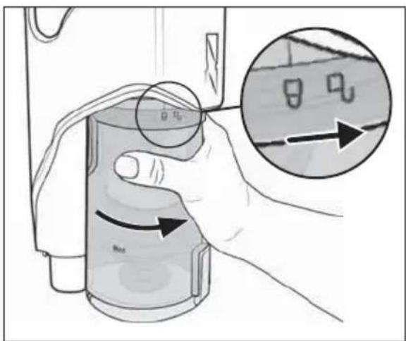
Fig. 28
Cleaning the rotary brush
ATTENTION!
▶ Only use the appliance with the rotary brush 21 properly mounted.
(i) Note
▶ Clean the rotary brush ^21 regularly to ensure proper operation of the appliance and avoid malfunctions.
1) Remove the floor brush 22 from the suction pipe 24 or from the appliance (see section Dismantling the appliance). Turn the floor brush 22 upside down.
2) Unlock the rotary brush 21 by sliding the rotary brush release 19 with your finger towards the symbol open). Remove the rotary brush holder 20 from the floor brush 22 (see Fig. 29).
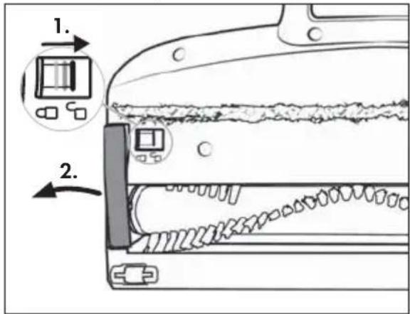
Fig. 29
3) Pull the rotary brush 21 out of the floor brush 22 by the bristles. Turn the rotary brush 21 slightly to make it easier to remove (see Fig. 30).
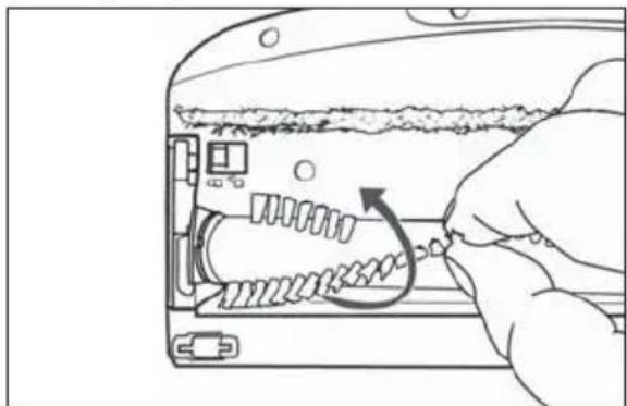
natural_image
Hand inserting a spring into a device casing (no text or symbols visible)
Fig. 30
4) Cut threads and hairs along the bristles of the rotary brush 21 with scissors (see Fig. 31). Remove threads and hair from the rotary brush 21.
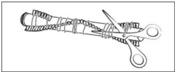
natural_image
Line drawing of a coiled spring with scissors (no text or symbols)
Fig. 31
5) Insert the rotary brush 21 into the floor brush 22. Turn the rotary brush 21 slightly to make it easier to insert.
6) Put the rotary brush holder 20 back into the floor brush 22. Push it down until it audibly clicks into the floor brush 22 (see Fig. 32).
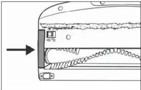
natural_image
Diagram of a car interior showing internal components and airflow direction (no text or symbols)
Fig. 32
Cleaning the appliance ⚠️ DANGER!
Always remove the barrel plug 11 of the mains adapter 10 from the charging socket 3 of the appliance before cleaning it. There is a risk of electric shock!
ATTENTION!
▶ Do not use aggressive, chemical or abrasive cleaning agents. They could damage the outer surfaces of the appliance.
▶ To avoid irreparable damage to the appliance, ensure that no moisture gets into it during cleaning.
- Clean the appliance housing and the attachments with a slightly damp cloth. For stubborn soiling use a mild detergent on the cloth.
- Dry all parts thoroughly before using the appliance again or storing it.
Storage
! ATTENTION!
▶ Never store the device when it is discharged. Prolonged storage in a discharged state can cause permanent damage to the battery. If the device is stored for a longer period of time, the charge level of the battery must be checked regularly. The optimum charge level is between 50% and 80%.
Place the appliance on the wall bracket when you are not using it.
- Attach the accessories holder ^17 to the suction pipe ^24 and place the accessory on the accessories holder ^17 for storage (see section After use).
◆ Store the appliance in a dust-free and dry location out of direct sunlight.
Disposal
Applies only to France:
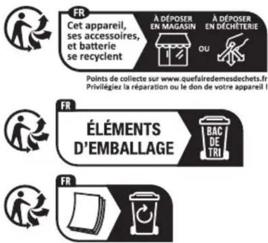
The product, its packaging and the operating instructions are recyclable. They are subject to an extended manufacturer responsibility and will be collected separately.
Disposal of the appliance
The adjacent symbol of a crossed-out dustbin means that this appliance is subject to Directive 2012/19/EU. This directive states that this appliance may not be disposed of in the normal household waste at the end of its useful life, but must be taken to specially set-up collection locations, recycling depots or disposal companies.
The disposal is free of charge for the user. Protect the environment and dispose of this appliance properly.
If your old appliance has stored any personal data, you are responsible for deleting it yourself before returning it.
If it is possible to do so without destroying the old appliance, remove the old batteries or rechargeable batteries before returning the appliance for disposal and take them to a separate collection point. In the case of permanently installed rechargeable batteries, you must indicate during disposal that the appliance contains a battery.

Your local community or municipal authorities can provide information on how to dispose of the worn-out product.
Disposal of the packaging

The packaging materials have been selected for their environmental friendliness and ease of disposal and are therefore recyclable.
Dispose of packaging materials that are no longer needed in accordance with applicable local regulations.
Dispose of the packaging in an environmentally friendly manner. Note the labelling on the packaging and separate the packaging material components for disposal, if necessary. The packaging material is labelled with abbreviations (a) and numbers (b) with the following meanings: 1-7: plastics, 20-22: paper and cardboard, 80-98: composites.
Applies only to Spain:

The packaging contains paper and/or cardboard components.

The packaging contains plastic and/or metal components.
Disposal of batteries
Batteries/rechargeable batteries must be treated as hazardous waste and must therefore be disposed of in an environmentally sound manner by appropriate bodies (dealers, specialist dealers, public municipal bodies, commercial disposal companies). Batteries/rechargeable batteries may contain toxic heavy metals.
The heavy metals contained are identified by letters below the symbol: Cd = cadmium, Hg = mercury, Pb = lead.
For this reason, do not dispose of batteries/rechargeable batteries in domestic waste. Take them to a specialist collection point.
Only return batteries that are fully discharged.
Ordering replacement parts
You can order replacement parts for this product on the Internet at www.kompernass.com.

Scan the QR code with your smartphone/tablet. You can use this QR code to go directly to our website to view and order the available spare parts.
i Note
▶ If you have problems with your online order, you can contact our service centre by phone or e-mail.
▶ Always quote the article number (IAN) 472296_2407 in your order.
▶ Please note that online ordering of replacement parts is not possible for all countries.
This appliance has a 3-year warranty valid from the date of purchase. If this product has any faults, you, the buyer, have certain statutory rights. Your statutory rights are not restricted in any way by the warranty described below.
Warranty conditions
The warranty period starts on the date of purchase. Please keep your receipt in a safe place. This will be required as proof of purchase.
If any material or manufacturing fault occurs within three years of the date of purchase of the product, we will either repair or replace the product for you or refund the purchase price (at our discretion). This warranty service requires that you present the defective appliance and the proof of purchase (receipt) within the three-year warranty period, along with a brief written description of the fault and of when it occurred.
If the defect is covered by the warranty, your product will either be repaired or replaced by us. The repair or replacement of a product does not signify the beginning of a new warranty period.
Warranty period and statutory claims for defects
The warranty period is not prolonged by repairs effected under the warranty. This also applies to replaced and repaired components. Any damage and defects present at the time of purchase must be reported immediately after unpacking. Repairs carried out after expiry of the warranty period shall be subject to a fee.
Scope of the warranty
This appliance has been manufactured in accordance with strict quality guidelines and inspected meticulously prior to delivery.
The warranty covers material faults or production faults. The warranty does not extend to product parts subject to normal wear and tear or to fragile parts which could be considered as consumable parts such as switches or parts made of glass.
The warranty does not apply if the product has been damaged, improperly used or improperly maintained. The directions in the operating instructions for the product regarding proper use of the product are to be strictly followed. Uses and actions that are discouraged in the operating instructions or which are warned against must be avoided.
This product is intended solely for private use and not for commercial purposes. The warranty shall be deemed void in cases of misuse or improper handling, use of force and modifications / repairs which have not been carried out by one of our authorised Service centres.
Warranty claim procedure
To ensure quick processing of your case, please observe the following instructions:
Please have the till receipt and the item number (IAN) 472296_2407 available as proof of purchase.
■ You will find the item number on the type plate on the product, an engraving on the product, on the front page of the operating instructions (below left) or on the sticker on the rear or bottom of the product.
If functional or other defects occur, please contact the service department listed either by telephone or by e-mail.
You can return a defective product to us free of charge to the service address that will be provided to you. Ensure that you enclose the proof of purchase (till receipt) and information about what the defect is and when it occurred.

You can download these instructions along with many other manuals, product videos and installation software at www.lidl-service.com.
This QR code will take you directly to the Lidl service page (www.lidl-service.com) where you can open your operating instructions by entering the item number (IAN) 472296_2407.
Service
GB Service Great Britain
Tel.: 0800 404 7657
E-Mail: kompernass@lidl.co.uk
IE Servicelreland
Tel.: 1800 101010
E-Mail: kompernass@lidl.ie
IAN 472296_2407
Importer
Please note that the following address is not the service address. Please use the service address provided in the operating instructions.
KOMPERNASS HANDELS GMBH
BURGSTRASSE 21
44867 BOCHUM
GERMANY
www.kompernass.com
Inhaltsverzeichnis
Einleitung 22
natural_image
Diagram showing two mechanical components with an arrow indicating motion or force (no text or symbols present)
Abb. 1
natural_image
Diagram of a vacuum cleaner with a downward arrow indicating motion (no text or symbols present)
Abb. 2
natural_image
Line drawing of a kitchen appliance with a side panel and a close-up view of its lid (no text or symbols)
Abb. 3
natural_image
Diagram of a mechanical component with internal parts and an arrow indicating direction (no text or symbols)
Abb. 4
natural_image
Line drawing of hands installing or adjusting a mechanical component with a tool (no text or symbols)
Abb. 5
natural_image
Technical line drawing of a mechanical component with an inset showing a close-up of a component (no text or symbols)
Abb. 6
natural_image
Line drawing of a handheld electronic device with ports and a small inset showing internal components (no text or symbols)
Abb. 7
natural_image
Diagram of a mechanical component with an inset close-up showing internal structure (no text or symbols)
Abb. 8
Abb. 9
natural_image
Line drawing of a vacuum cleaner with three labeled parts (no text or symbols present)
Abb. 10
Gerät einschalten
natural_image
Technical line drawing of a mechanical component with an arrow indicating assembly or motion (no text or symbols)
Abb. 14
natural_image
Line drawing of a hand using a tool to adjust or install a device (no text or symbols present)
Abb. 16
natural_image
Technical diagram of a mechanical device with two circular components and a central rotating wheel (no text or symbols)
Abb. 17
natural_image
Illustration of a hand using a tool to lift a circular component, with an arrow indicating the process (no text or symbols present)
Abb. 18
i Hinweis
natural_image
Technical line drawing of a mechanical device with a separate inset showing three cylindrical components (no text or symbols)
Abb. 19
natural_image
Technical line drawing of a mechanical device with multiple ports and a central shaft (no text or symbols)
Abb. 20
natural_image
Diagram of a mechanical device pouring granular material into a container (no text or symbols)
Abb. 21
Abb. 22
natural_image
Diagram of a cylindrical device with internal components and directional arrows, no text or symbols present
Abb. 23
natural_image
Diagram of a mechanical device with a cylindrical component and an upward arrow indicating motion (no text or symbols)
Abb. 24
Abb. 25
natural_image
Diagram showing a mechanical component being lowered into a cylindrical housing, with no visible text or symbols.
Abb. 26
i Hinweis
natural_image
Diagram showing a cylindrical filter being inserted into a mechanical component, with an arrow indicating the process (no text or symbols present)
Abb. 27
Abb. 28
Bürstenrolle reinigen
! ACHTUNG!
Abb. 29
natural_image
Line drawing of a hand inserting a spring into a device casing (no text or symbols)
Abb. 30
natural_image
Line drawing of a coiled spring with scissors and ring (no text or symbols)
Abb. 31
natural_image
Diagram of a device's internal structure showing a panel with a mouse and gear, no text or symbols present
Abb. 32
Gerät reinigen
GEFAHR!
KOMPERNASS HANDELS GMBH
BURGSTRASSE 21
44867 BOCHUM
DEUTSCHLAND
www.kompernass.com
Table des matières
Introduction 44
natural_image
Diagram showing two mechanical components with an arrow indicating direction (no text or symbols)
Fig. 1
natural_image
Illustration of a hand holding a mechanical device with a downward arrow indicating motion (no text or symbols)
Fig. 2
natural_image
Line drawing of a hand tool interacting with a device labeled 'Hand tool' (no text or symbols on the diagram itself)
Fig. 3
natural_image
Diagram of a mechanical switch or connector assembly with internal components and an arrow indicating direction (no text or symbols)
Fig. 4
natural_image
Line drawing of hands installing or adjusting a component with a tool (no text or symbols visible)
Fig. 5
natural_image
Technical line drawing of a mechanical component with an inset close-up showing internal components (no text or symbols)
Fig. 6
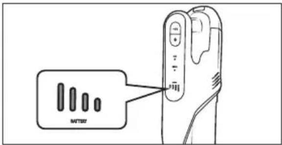
Fig. 7
natural_image
Technical diagram of a mechanical component with an inset close-up showing internal structure (no text or symbols)
Fig. 8
Fig. 9

natural_image
Technical line drawing of a vacuum cleaner with mounting bracket and handle (no text or symbols)
Fig. 10
Allumer l'appareil
natural_image
Technical line drawing of a mechanical component with an arrow indicating assembly or motion (no text or symbols)
Fig. 14
natural_image
Line drawing of a hand using a tool to adjust or install a device (no text or symbols present)
Fig. 16
natural_image
Technical diagram of a mechanical device with two circular components and a central rotating component, showing no text or symbols.
Fig. 17
natural_image
Illustration of a hand using a tool to lift a circular component, with an arrow indicating the direction (no text or symbols present)
Fig. 18
i Remarque
natural_image
Technical line drawing of a handheld device with a separate inset showing three cylindrical components (no text or symbols)
Fig. 19
natural_image
Technical line drawing of a mechanical device with three ports and a central shaft, showing internal components and directional arrows (no text or symbols)
Fig. 20
natural_image
Diagram of a mechanical device pouring granular material into a container (no text or symbols)
Fig. 21
Fig. 22
natural_image
Diagram of a cylindrical device with internal components and directional arrows, no text or symbols present
Fig. 23
natural_image
Diagram of a mechanical device with a cylindrical component and an ascending arrow, no text or symbols present
Fig. 24
Fig. 25
natural_image
Diagram showing a mechanical component being lifted by a downward arrow, with no visible text or symbols.
Fig. 26
i Remarque
natural_image
Diagram showing a cylindrical filter being inserted into a mechanical component, with an arrow indicating the process (no text or symbols present)
Fig. 27
Fig. 28
natural_image
Hand inserting a component into a device casing, showing internal wiring and a circular arrow indicating rotation (no text or symbols)
Fig. 30
natural_image
Line drawing of a coiled spring with scissors cutting through it (no text or symbols)
Fig. 31
natural_image
Diagram of a device interior showing internal components and a directional arrow (no text or symbols)
Fig. 32
Nettoyer l'appareil
DANGER!
KOMPERNASS HANDELS GMBH
BURGSTRASSE 21
44867 BOCHUM
ALLEMAGNE
www.kompernass.com
Inhoud
Inleiding 66
⚠ WAARSCHUWING! LETSELGEVAAR!
natural_image
Diagram showing two mechanical components with an arrow indicating a process or transformation (no text or symbols present)
Afb. 1
natural_image
Illustration of a hand holding a mechanical device with an arrow indicating process (no text or symbols)
Afb. 2
natural_image
Line drawing of a hand tool interacting with a device, showing a left-hand tool and a right-hand tool (no text or symbols present)
Afb. 3
natural_image
Diagram of a mechanical switch or socket assembly with internal components and an arrow indicating direction (no text or symbols)
Afb. 4
natural_image
Line drawing of hands installing or adjusting a component with a tool (no text or symbols)
Afb. 5
natural_image
Technical line drawing of a mechanical component with an inset close-up showing internal components (no text or symbols)
Afb. 6
Afb. 7
natural_image
Diagram of a mechanical component with an inset close-up showing internal structure (no text or symbols)
Afb. 8
Afb. 9

natural_image
Technical line drawing of a vacuum cleaner assembly with mounting bracket and handle (no text or symbols)
Afb. 10
natural_image
Technical line drawing of a mechanical component with an arrow indicating assembly or adjustment (no text or symbols present)
Afb. 14
natural_image
Line drawing of a hand using a tool to adjust or install a device (no text or symbols present)
Afb. 16
natural_image
Diagram of a mechanical device with two circular components and a central rotating wheel (no text or symbols)
Afb. 17
natural_image
Illustration of a hand using a tool to adjust a circular component with an arrow indicating upward motion (no text or symbols present)
Afb. 18
i Opmerking
natural_image
Technical line drawing of a mechanical device with a separate inset showing three cylindrical components (no text or symbols)
Afb. 19
natural_image
Technical line drawing of a mechanical device with multiple ports and a central shaft (no text or symbols)
Afb. 20
natural_image
Diagram of a mechanical device pouring granular material into a container (no text or symbols)
Afb. 21
Afb. 22
natural_image
Diagram of a cylindrical device with internal components and directional arrows, no text or symbols present
Afb. 23
natural_image
Diagram of a mechanical device with a cylindrical component and an upward arrow indicating motion (no text or symbols)
Afb. 24
Afb. 25
natural_image
Diagram showing a mechanical device with a top component and a side view of a cylindrical device, both without any text or symbols.
Afb. 26
i Opmerking
natural_image
Diagram showing a cylindrical device with a hollow top and a side view of its internal structure, both without any text or symbols.
Afb. 27
Afb. 28
Borstelrol reinigen
LET OP!
Afb. 29
natural_image
Hand inserting a component into a device casing, showing internal wiring and a circular arrow indicating rotation (no text or symbols)
Afb. 30
natural_image
Line drawing of a coiled spring with scissors cutting through it (no text or symbols)
Afb. 31
natural_image
Diagram of a device interior showing internal components and a directional arrow (no text or symbols)
Afb. 32
Apparaat reinigen
GEVAAR!
KOMPERNASS HANDELS GMBH
BURGSTRASSE 21
44867 BOCHUM
DUITSLAND
www.kompernass.com
Obsah
Úvod....86
natural_image
Diagram showing two mechanical components with an arrow indicating direction (no text or symbols)
Obr. 1
natural_image
Illustration of a hand holding a mechanical device with an arrow indicating downward motion (no text or symbols)
Obr. 2
natural_image
Line drawing of a blender and its internal component, showing a handle and lid assembly (no text or symbols)
Obr. 3
natural_image
Diagram of a mechanical switch or connector assembly with internal components and an arrow indicating direction (no text or symbols)
Obr. 4
natural_image
Line drawing of hands installing or adjusting a component with a tool (no text or symbols)
Obr. 5
natural_image
Technical line drawing of a mechanical component with an inset showing a close-up of a connector detail (no text or symbols)
Obr. 6
Obr. 7
natural_image
Diagram of a mechanical component with an inset close-up showing internal structure (no text or symbols)
Obr. 8
Obsluha a provoz
POZOR!
Obr. 9
natural_image
Technical line drawing of a vacuum cleaner assembly with mounting bracket and vertical guide (no text or symbols)
Obr. 10
Zapnutí přístroje
Obr. 11
podlahový kartáč
natural_image
Technical line drawing of a mechanical component with an arrow indicating assembly or motion (no text or symbols)
Obr. 14
natural_image
Line drawing of a hand using a tool to lift a device into a package (no text or symbols)
Obr. 16
natural_image
Technical diagram of a mechanical device with two circular components and a central rotating wheel (no text or symbols)
Obr. 17
natural_image
Illustration of a hand using a tool to adjust a circular component, with no visible text or symbols.
Obr. 18
i Upozornění
natural_image
Line drawing of a handheld device with a left-side arrow indicating a mechanical component (no text or symbols present)
Obr. 19
natural_image
Technical line drawing of a mechanical device with multiple ports and a central shaft (no text or symbols)
Obr. 20
natural_image
Diagram of a mechanical device pouring granular material into a container (no text or symbols)
Obr. 21
Obr. 22
natural_image
Diagram of a cylindrical device with internal components and directional arrows, no text or symbols present
Obr. 23
natural_image
Diagram of a mechanical device with a cylindrical component and an upward arrow indicating motion (no text or symbols)
Obr. 24
Obr. 25
i Upozornění
natural_image
Diagram showing a mechanical device with a downward arrow indicating a process or transformation (no text or symbols present)
Obr. 26
i Upozornění
natural_image
Diagram showing a mechanical component being lifted by a force, with an arrow indicating downward motion (no text or symbols present)
Obr. 27
Obr. 28
natural_image
Hand inserting a spring into a device casing (no text or symbols visible)
Obr. 30
natural_image
Line drawing of a coiled spring with scissors cutting through it (no text or symbols)
Obr. 31
natural_image
Diagram of a mechanical component with internal structure and directional arrow (no text or symbols)
Obr. 32
Čištění přístroje
NEBEZPEČÍ!
KOMPERNASS HANDELS GMBH
BURGSTRASSE 21
44867 BOCHUM
NĚMECKO
www.kompernass.com
Spis treści
W step 106
natural_image
Diagram showing two mechanical components with an arrow indicating direction (no text or symbols)
Rys. 1
natural_image
Illustration of a hand holding a mechanical device with an arrow indicating downward motion (no text or symbols)
Rys. 2
natural_image
Line drawing of a hand tool interacting with a device labeled 'AT&T 4.01 SIM' (no text or symbols on the diagram itself)
Rys. 3
natural_image
Diagram of a mechanical switch or socket assembly with internal components and an arrow indicating direction (no text or labels)
Rys. 4
natural_image
Illustration of hands installing or adjusting a component with a tool (no text or symbols visible)
Rys. 5
natural_image
Technical line drawing of a mechanical component with an inset showing a close-up of a connector detail (no text or symbols)
Rys. 6
Rys. 7
Rys. 8
Rys. 9

natural_image
Technical line drawing of a vacuum cleaner assembly with mounting bracket and handle (no text or symbols)
Rys. 10
Rys. 11
Szczotka do podłóg
natural_image
Technical line drawing of a mechanical component with an arrow indicating assembly or motion (no text or symbols)
Rys. 14
natural_image
Line drawing of a hand using a tool to adjust or install a device (no text or symbols present)
Rys. 16
natural_image
Diagram of a mechanical device with two circular components and a central rotating wheel, showing no text or symbols.
Rys. 17
natural_image
Illustration of a hand using a tool to lift a circular component, with no visible text or symbols.
Rys. 18
i Wskazówka
natural_image
Technical line drawing of a handheld device with a separate inset showing three cylindrical components (no text or symbols)
Rys. 19
natural_image
Technical line drawing of a mechanical device with multiple ports and a central shaft (no text or symbols)
Rys. 20
natural_image
Diagram of a mechanical device pouring granular material into a container (no text or symbols)
Rys. 21
Rys. 22
natural_image
Diagram of a cylindrical device with internal components and directional arrows, no text or symbols present
Rys. 23
natural_image
Diagram of a mechanical device with a cylindrical component and an upward arrow indicating motion (no text or symbols)
Rys. 24
Rys. 25
natural_image
Diagram showing a mechanical component being lifted by a downward arrow, with no visible text or symbols.
Rys. 26
i Wskazówka
natural_image
Diagram showing a cylindrical filter being inserted into a mechanical component, with a downward arrow indicating the process (no text or symbols present)
Rys. 27
natural_image
Hand inserting a device into a device casing, showing internal components and a circular arrow indicating rotation (no text or symbols)
Rys. 30
natural_image
Line drawing of a coiled spring with scissors cutting through it (no text or symbols)
Rys. 31
natural_image
Diagram of a car interior showing internal components and airflow direction (no text or symbols)
Rys. 32
KOMPERNASS HANDELS GMBH
BURGSTRASSE 21
44867 BOCHUM
NIEMCY
www.kompernass.com
Obsah
Úvod....126
natural_image
Diagram showing two mechanical components with an arrow indicating direction (no text or symbols)
Obr. 1
natural_image
Illustration of a hand holding a mechanical device with a downward arrow indicating motion (no text or symbols)
Obr. 2
natural_image
Line drawing of a blender and its internal component, showing a close-up of the blender's handle (no text or symbols present)
Obr. 3
natural_image
Diagram of a mechanical switch or socket assembly with internal components and an arrow indicating direction (no text or labels)
Obr. 4
natural_image
Line drawing of hands assembling a mechanical component with a tool (no text or symbols)
Obr. 5
natural_image
Technical line drawing of a device with an inset showing a close-up of a mechanical component (no text or symbols)
Obr. 6

Obr. 7
natural_image
Diagram of a mechanical component with an inset close-up showing internal structure (no text or symbols)
Obr. 8
Obsluha a prevádzka
! POZOR!
Obr. 9

natural_image
Technical line drawing of a vacuum cleaner with mounting bracket and handle (no text or symbols)
Obr. 10
Zapnutie prístroja
Obr. 11
Podlahová kefa
natural_image
Technical line drawing showing a mechanical assembly with a cylindrical component and a separate pipe fitting (no text or symbols)
Obr. 14
natural_image
Line drawing of hands using a tool to adjust or install a device (no text or symbols present)
Obr. 16
natural_image
Diagram of a mechanical device with two circular components and a central rotating wheel (no text or symbols)
Obr. 17
natural_image
Illustration of a hand using a tool to lift a circular component, with an arrow indicating the process (no text or symbols present)
Obr. 18
i Upozornenie
Pred použitím podložky na stierani ^34 trochu navlhčite, aby lepšie absorbovali nečistoty.
natural_image
Technical line drawing of a handheld device with a separate inset showing three cylindrical components (no text or symbols)
Obr. 19
natural_image
Technical line drawing of a mechanical device with three vertical components and an upward arrow indicating motion (no text or symbols)
Obr. 20
Vysávač nasadte do držiaka na stenu 18.
Proces nabijania spustite, ked' akumulátor 2
má ešte malé zvyškové nabitie
Čistenie
⚠️ VÝSTRAHA!
natural_image
Diagram of a mechanical device pouring granular material into a container (no text or symbols)
Obr. 21
Obr. 22
natural_image
Diagram of a cylindrical device with internal components and directional arrows, no text or symbols present
Obr. 23
natural_image
Diagram of a mechanical device with a cylindrical component and an ascending arrow, no text or symbols present
Obr. 24
Obr. 25
natural_image
Diagram showing a mechanical component being lifted by a downward arrow, with no visible text or symbols.
Obr. 26
i Upozornenie
natural_image
Diagram showing a cylindrical filter being inserted into a mechanical component, with an arrow indicating the process (no text or symbols present)
Obr. 27
Obr. 28
Obr. 29
natural_image
Hand inserting a spring into a device casing (no text or symbols visible)
Obr. 30
natural_image
Line drawing of a mechanical tool with coiled spring and hook (no text or symbols)
Obr. 31
5) Rotačnú kefu21 vložte do podlahovej kefy 22. Rotačnú kefu 21 pritom trochu otočte, aby ste ju mohli l'ahko vložit'.
natural_image
Diagram of a car interior showing internal components and a directional arrow (no text or symbols)
Obr. 32
Čistenie prístroja
NEBEZPEČENSTVO!
KOMPERNASS HANDELS GMBH
BURGSTRASSE 21
44867 BOCHUM
NEMECKO
www.kompernass.com
Índice
Introducción....146
Uso previsto 146
natural_image
Diagram showing two mechanical components with an arrow indicating a process or transformation (no text or symbols present)
Fig. 1
natural_image
Illustration of a hand holding a mechanical device with an arrow indicating downward motion (no text or symbols)
Fig. 2
natural_image
Line drawing of a blender and its internal component, showing a device with a handle and lid (no text or symbols)
Fig. 3
natural_image
Diagram of a mechanical component with internal parts and an arrow indicating direction (no text or symbols)
Fig. 4
natural_image
Illustration of hands installing or adjusting a component with a tool (no text or symbols visible)
Fig. 5
natural_image
Technical line drawing of a device with an inset showing a close-up of a mechanical component (no text or symbols)
Fig. 6
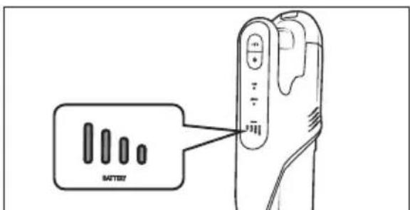
Fig. 7
natural_image
Diagram of a mechanical component with an inset close-up showing internal structure (no text or symbols)
Fig. 8
Fig. 9
natural_image
Technical line drawing of a right-angle mechanical bracket with mounting base and support structure (no text or symbols)
Fig. 10
natural_image
Technical line drawing of a mechanical component with an arrow indicating assembly or adjustment (no text or symbols present)
Fig. 14
natural_image
Line drawing of a hand using a tool to lift a device into a container (no text or symbols)
Fig. 16
natural_image
Technical diagram of a mechanical device with two circular components and a central rotating component, showing no text or symbols.
Fig. 17
natural_image
Illustration of a hand using a tool to lift a circular component, with an arrow indicating the motion (no text or symbols present)
Fig. 18
i Indicación
natural_image
Technical line drawing of a mechanical device with a separate inset showing three cylindrical components (no text or symbols)
Fig. 19
natural_image
Technical line drawing of a mechanical device with multiple ports and a central shaft (no text or symbols)
Fig. 20
natural_image
Diagram of a mechanical device pouring granular material into a container (no text or symbols)
Fig. 21
Fig. 22
natural_image
Diagram of a cylindrical device with internal components and directional arrows, no visible text or symbols
Fig. 23
natural_image
Diagram of a mechanical device with a cylindrical component and an upward arrow indicating motion (no text or symbols)
Fig. 24
Fig. 25
i Indicación
natural_image
Diagram showing a mechanical device with a downward arrow indicating a process or transformation (no text or symbols present)
Fig. 26
i Indicación
natural_image
Diagram showing a filter component being inserted into a cylindrical device, with a downward arrow indicating the process (no text or symbols present)
Fig. 27
Fig. 28
Fig. 29
natural_image
Hand inserting a device into a device casing, showing internal components and a circular arrow indicating rotation (no text or symbols)
Fig. 30
natural_image
Line drawing of a coiled spring with scissors cutting through it (no text or symbols)
Fig. 31
natural_image
Diagram of a car interior showing airflow direction and component placement (no text or symbols)
Fig. 32
KOMPERNASS HANDELS GMBH
BURGSTRASSE 21
44867 BOCHUM
ALEMANIA
www.kompernass.com
Indholdsfortegnelse
Indledning 170
Anvendelsesområde 170
natural_image
Diagram showing two mechanical components with an arrow indicating direction (no text or symbols)
Fig. 1
natural_image
Illustration of a hand holding a mechanical device with an arrow indicating process (no text or symbols)
Fig. 2
natural_image
Line drawing of a hand tool and a device with an arrow indicating process (no text or symbols)
Fig. 3
natural_image
Diagram of a mechanical switch or electrical component with internal parts and an arrow indicating direction (no text or symbols)
Fig. 4
natural_image
Illustration of hands installing or adjusting a mechanical component with a tool (no text or symbols visible)
Fig. 5
natural_image
Technical line drawing of a mechanical component with an inset close-up showing internal components (no text or symbols)
Fig. 6

Fig. 7
natural_image
Diagram of a mechanical component with an inset close-up showing internal structure (no text or symbols)
Fig. 8
Fig. 9

natural_image
Technical line drawing of a vacuum cleaner assembly with three mounting brackets and a vertical support (no text or symbols)
Fig. 10
Fig. 11
Gulvbørste
natural_image
Technical line drawing of a mechanical component with an arrow indicating assembly or motion (no text or symbols)
Fig. 14
natural_image
Line drawing of a hand using a tool to adjust or install a device (no text or symbols present)
Fig. 16
natural_image
Diagram of a mechanical device with two circular components and a central rotating wheel (no text or symbols)
Fig. 17
natural_image
Illustration of a hand using a tool to adjust a circular component with a pointer (no text or symbols)
Fig. 18
i Bemærk
natural_image
Technical line drawing of a handheld device with a cylindrical component and a separate stack of three cups (no text or symbols)
Fig. 19
natural_image
Technical line drawing of a mechanical device with multiple ports and a central shaft (no text or symbols)
Fig. 20
natural_image
Diagram of a hand pouring granular material into a container (no text or symbols)
Fig. 21
Fig. 22
natural_image
Diagram of a cylindrical device with internal components and directional arrows, no visible text or symbols
Fig. 23
natural_image
Diagram of a mechanical device with a cylindrical component and an upward arrow indicating motion (no text or symbols)
Fig. 24
Fig. 25
i Bemærk
natural_image
Diagram showing a mechanical component being lifted by a downward arrow, with no visible text or symbols.
Fig. 26
i Bemærk
natural_image
Diagram showing a filter component being inserted into a cylindrical device, with an arrow indicating the process (no text or symbols present)
Fig. 27
Fig. 28
Fig. 29
natural_image
Hand inserting a component into a device casing, showing internal wiring and mounting holes (no text or symbols)
Fig. 30
natural_image
Line drawing of a coiled spring with scissors cutting through it (no text or symbols)
Fig. 31
natural_image
Diagram of a mechanical device showing internal components and a directional arrow (no text or symbols)
Fig. 32
KOMPERNASS HANDELS GMBH
BURGSTRASSE 21
44867 BOCHUM
TYSKLAND
www.kompernass.com
Indice
Introduzione....190
Uso conforme 190
natural_image
Diagram showing two mechanical components with an arrow indicating direction (no text or symbols)
Fig. 1
natural_image
Illustration of a hand holding a mechanical device with an arrow indicating downward motion (no text or symbols)
Fig. 2
natural_image
Line drawing of a kitchen appliance with a right-hand rule for adding a component (no text or symbols)
Fig. 3
natural_image
Diagram of a mechanical component with internal parts and an arrow indicating direction (no text or symbols)
Fig. 4
natural_image
Line drawing of hands installing or adjusting a mechanical component with a tool (no text or symbols)
Fig. 5
natural_image
Technical line drawing of a device with an inset close-up showing internal components (no text or symbols)
Fig. 6

Fig. 7
natural_image
Diagram of a mechanical component with an inset close-up showing internal structure (no text or symbols)
Fig. 8
Fig. 9
natural_image
Technical line drawing of a vacuum cleaner assembly with mounting bracket (no text or symbols)
Fig. 10
natural_image
Technical line drawing of a mechanical component with an arrow indicating assembly or motion (no text or symbols)
Fig. 14
natural_image
Line drawing of hands using a tool to adjust or install a device (no text or symbols present)
Fig. 16
natural_image
Technical diagram of a mechanical device with circular components and a pointer indicating direction (no text or symbols)
Fig. 17
natural_image
Illustration of a hand using a tool to lift a circular component, with an arrow indicating the direction (no text or symbols present)
Fig. 18
i Nota
natural_image
Technical line drawing of a mechanical device with a separate inset showing three cylindrical components (no text or symbols)
Fig. 19
natural_image
Technical line drawing of a mechanical device with multiple ports and a central shaft (no text or symbols)
Fig. 20
natural_image
Diagram of a mechanical device pouring liquid into a container (no text or symbols)
Fig. 21
Fig. 22
natural_image
Diagram of a cylindrical device with internal components and directional arrows, no text or symbols present
Fig. 23
natural_image
Diagram of a mechanical device with a cylindrical component and an upward arrow indicating motion (no text or symbols)
Fig. 24
Fig. 25
natural_image
Diagram showing a mechanical device with a downward arrow indicating a process or transformation (no text or symbols present)
Fig. 26
i Nota
natural_image
Diagram showing a cylindrical filter being inserted into a mechanical component, with an arrow indicating the process (no text or symbols present)
Fig. 27
Fig. 28
Fig. 29
natural_image
Hand inserting a component into a device casing, showing internal wiring and a circular arrow indicating rotation (no text or symbols)
Fig. 30
natural_image
Line drawing of a coiled spring with scissors cutting through it (no text or symbols)
Fig. 31
natural_image
Diagram of a device interior showing internal components and a directional arrow (no text or symbols)
Fig. 32
KOMPERNASS HANDELS GMBH
BURGSTRASSE 21
44867 BOCHUM
GERMANIA
www.kompernass.com
Tartalomjegyzék
Bevezető 212
natural_image
Diagram showing two mechanical components with an arrow indicating direction (no text or symbols)
- ábra
natural_image
Illustration of a hand holding a mechanical device with a downward arrow indicating motion (no text or symbols)
- ábra
natural_image
Line drawing of a kitchen appliance with a right-hand rule for adding a component (no text or symbols)
- ábra
natural_image
Diagram of a mechanical switch or connector with internal components and an arrow indicating direction (no text or symbols)
- ábra
natural_image
Line drawing of hands assembling a mechanical component with a tool (no text or symbols)
- ábra
natural_image
Technical line drawing of a mechanical component with an inset close-up showing internal components (no text or symbols)
- ábra

- ábra
natural_image
Diagram of a mechanical component with an inset close-up showing internal structure (no text or symbols)
- ábra
- ábra

natural_image
Technical line drawing of a vacuum cleaner assembly with mounting bracket and handle (no text or symbols)
- ábra
natural_image
Technical line drawing of a mechanical component with an arrow indicating assembly or motion (no text or symbols)
- ábra
natural_image
Line drawing of hands using a tool to adjust or install a device (no text or symbols present)
- ábra
natural_image
Technical diagram of a mechanical device with two circular components and a central rotating knob (no text or symbols)
- ábra
natural_image
Illustration of a hand using a tool to adjust or clean a circular object, with no visible text or symbols.
- ábra
i Tudnivaló
natural_image
Line drawing of a handheld device with a left-side arrow indicating a component or operation (no text or symbols present)
- ábra
natural_image
Technical line drawing of a mechanical device with multiple ports and a central shaft (no text or symbols)
- ábra
natural_image
Diagram of a mechanical device pouring granular material into a container (no text or symbols)
- ábra
natural_image
Diagram of a cylindrical device with internal components and directional arrows, no text or symbols present
- ábra
natural_image
Diagram of a mechanical device with a cylindrical component and an ascending arrow, no text or symbols present
- ábra
- ábra
natural_image
Diagram showing a mechanical component being lifted by a downward arrow, with no visible text or symbols.
- ábra
iTudnivaló
natural_image
Diagram showing a cylindrical filter component being inserted into a mechanical component, with an arrow indicating the process (no text or symbols present)
- ábra
- ábra
natural_image
Hand inserting a component into a device casing, showing internal wiring and a circular arrow indicating rotation (no text or symbols)
- ábra
natural_image
Line drawing of a coiled spring with scissors cutting through it (no text or symbols)
- ábra
natural_image
Diagram of a car interior showing airflow direction and component placement (no text or symbols)
- ábra
KOMPERNASS HANDELS GMBH
BURGSTRASSE 21
44867 BOCHUM
NÉMETORSZÁG
www.kompernass.com

KOMPERNASS HANDELS GMBH
BURGSTRASSE 21
44867 BOCHUM
GERMANY
www.kompernass.com
Last Information Update · Stand der Informationen · Version des informations
Stand van de informatie · Stav informací · Stan informacji · Stav informácií
Estado de las informaciones · Tilstand af information · Versione delle informazioni