STAR_ATFE_05 - Office Fromm & Starck - Free user manual and instructions
Find the device manual for free STAR_ATFE_05 Fromm & Starck in PDF.

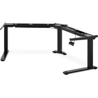
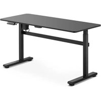
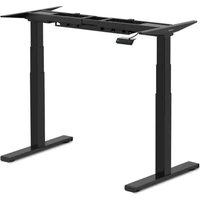
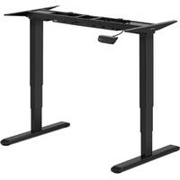
| Product type | Electric sit-stand desk |
| Brand | Fromm & Starck |
| Model | STAR_ATFE_05 |
| Rated voltage | 230 V~ |
| Frequency | 50 Hz |
| Protection class | II |
| Protection degree (IP) | 20 |
| Width (adjustable) | 1000 - 1700 mm |
| Depth | 650 mm |
| Height (adjustable) | 620 - 1280 mm |
| Maximum load capacity | 125 kg |
| Maximum adjustment speed | 38 mm/s |
| Working temperature | -5 °C to 40 °C |
| Number of motors | 2 |
| Control type | Button control panel |
| Cable management | Yes (cable duct and adhesive clips) |
| Frame material | Steel |
| Cleaning | Soft damp cloth, do not immerse |
| Maintenance | Regularly check fastenings and proper operation |
| Safety | Do not sit or climb, stop before cleaning |
| Usage | Indoor, private use |
| Adjustable feet | Yes (leveling pads) |
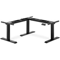
| Included accessories | Crossbar, lateral supports, lifting columns, feet, mounting plate, control box, cable duct, hooks, control panel, screws, washers |
Frequently Asked Questions - STAR_ATFE_05 Fromm & Starck
User questions about STAR_ATFE_05 Fromm & Starck
0 question about this device. Answer the ones you know or ask your own.
Ask a new question about this device
Download the instructions for your Office in PDF format for free! Find your manual STAR_ATFE_05 - Fromm & Starck and take your electronic device back in hand. On this page are published all the documents necessary for the use of your device. STAR_ATFE_05 by Fromm & Starck.
USER MANUAL STAR_ATFE_05 Fromm & Starck
natural_image
Technical line drawing of a mechanical assembly with a hand operating a bracket and a close-up inset showing a component (no text or symbols)natural_image
Line drawing of a hand operating a tool on a metal frame structure (no text or symbols)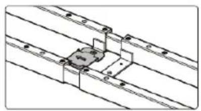
natural_image
Pure technical line drawing of a mechanical assembly with no text or symbols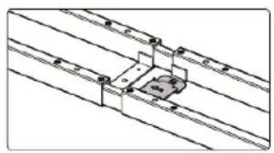
natural_image
Pure technical line drawing of a mechanical assembly with no text or symbolsnatural_image
Technical line drawing of a mechanical assembly with two views (1 and 2) showing internal components connected to wires, no text or symbols present.natural_image
Technical line drawing of a mechanical assembly with a rotating component (no text or symbols)natural_image
Technical line drawing of a structural frame with vertical supports and a hanging control unit (no text or symbols)natural_image
Technical line drawing of a mechanical assembly with no visible text or symbolsnatural_image
Line drawings of a simple table with legs and supports, showing structural details and a close-up of the lid (no text or symbols)The user manual is designed to assist in the safe and trouble-free use of the device. The product is designed and manufactured in accordance with strict technical guidelines, using state-of-the-art technologies and components. Additionally, it is produced in compliance with the most stringent quality standards.
DO NOT USE THE DEVICE UNLESS YOU HAVE THOROUGHLY READ AND UNDERSTOOD THIS USER MANUAL.
To increase the product life of the device and to ensure trouble-free operation, use it in accordance with this user manual and regularly perform maintenance tasks. The technical data and specifications in this user manual are up to date. The manufacturer reserves the right to make changes associated with quality improvement. The device is designed to reduce noise emission risks to a minimum, taking into account technological progress and noise reduction opportunities.
Legend
CE | The product satisfies the relevant safety standards.Read instructions before use. |
 | The product must be recycled. |
 | WARNING! or CAUTION! or REMEMBER! Applicable to the given situation.(general warning sign) |
 | ATTENTION! Electric shock warning! |
 | Class II protection device with double insulation. |
 | Only use indoors. |

PLEASE NOTE! Drawings in this manual are for illustration purposes only and in some details may differ from the actual product.
The original operation manual is written in German. Other language versions are translations from the German.
2. Usage safety

ATTENTION! Read all safety warnings and all instructions. Failure to follow the warnings and instructions may result in electric shock, fire and/or serious injury or even death.
The terms "device" or "product" are used in the warnings and instructions to refer to an ELECTRIC SIT STAND DESK FRAME.
2.1. Electrical safety
a) The plug must fit the socket. Do not modify the plug in any way. Using original plugs and matching sockets reduces the risk of electric shock.
b) Avoid touching earthed elements such as pipes, heaters, boilers and refrigerators. There is an increased risk of electric shock if the earthed device is exposed to rain, comes into direct contact with a wet surface or is operating in a damp environment. Water getting into the device increases the risk of damage to the device and of electric shock.
c) Do not touch the device with wet or damp hands.
d) Use the cable only for its designated use. Never use it to carry the device or to pull the plug out of a socket. Keep the cable away from heat sources, oil, sharp edges or moving parts. Damaged or tangled cables increase the risk of electric shock.
e) If using the device in a damp environment cannot be avoided, a residual current device (RCD) should be applied. The use of an RCD reduces the risk of electric shock.
f) Do not use the device if the power cord is damaged or shows obvious signs of wear. A damaged power cord should be replaced by a qualified electrician or the manufacturer's service centre.
g) To avoid electric shock, do not immerse the cord, plug or device in water or other liquids. Do not use the device on wet surfaces.
2.2. Safety in the workplace
a) Make sure the workplace is clean and well lit. A messy or poorly lit workplace may lead to accidents. Try to think ahead, observe what is going on and use common sense when working with the device.
b) If you are unsure about whether the product is operating correctly or if you find damage, please contact the manufacturer's service centre.
c) Only the manufacturer's service centre may make repairs to the product. Do not attempt to make repairs yourself!
d) Regularly inspect the condition of the safety labels. If the labels are illegible, they must be replaced.
e) Please keep this manual available for future reference. If this device is passed on to a third party, the manual must be passed on with it.
f) Keep packaging elements and small assembly parts in a place not available to children.
g) If this device is used together with another equipment, the remaining instructions for use shall also be followed.
h) The product may be used by children over 8 years of age who have been instructed on how to use it, and are under the care of an adult.
2.3. Personal safety
a) Do not use the device when tired, ill or under the influence of alcohol, narcotics or medication which can significantly impair the ability to operate the device.
b) The device is not designed to be handled by persons (including children) with limited mental and sensory functions or persons lacking relevant experience and/or knowledge unless they are supervised by a person responsible for their safety or they have received instruction on how to operate the device.
c) The device can be handled only by physically fit persons who are capable of handling it, properly trained, familiar with this manual and trained within the scope of occupational health and safety.
d) When working with the device, use common sense and stay alert. Temporary loss of concentration while using the device may lead to serious injuries.
e) The device is not a toy. Children must be supervised to ensure that they do not play with the device.
2.4. Safe device use
a) Do not overload the device. Use the appropriate tools for the given task. A correctly-selected device will perform the task for which it was designed better and in a safer manner.
b) Do not use the device if the ON/OFF switch does not function properly (does not switch the device on and off). Devices which cannot be switched on and off using the ON/OFF switch are hazardous, should not be operated and must be repaired.
c) Disconnect the device from the power supply before commencement of adjustment, cleaning and maintenance. Such a preventive measure reduces the risk of accidental activation.
d) When not in use, store in a safe place, away from children and people not familiar with the device who have not read the user manual. The device may pose a hazard in the hands of inexperienced users.
e) Keep the device in perfect technical condition. Before each use check for general damage and especially check for cracked parts or elements and for any other conditions which may impact the safe operation of the device. If damage is discovered, hand over the device for repair before use.
f) Device repair or maintenance should be carried out by qualified persons, only using original spare parts. This will ensure safe use.
g) To ensure the operational integrity of the device, do not remove factory-fitted guards and do not loosen any screws.
h) When transporting and handling the device between the warehouse and the destination, observe the occupational health and safety principles for manual
transport operations which apply in the country where the device will be used.
i) Clean the device regularly to prevent stubborn grime from accumulating.
j) The device is not a toy. Cleaning and maintenance may not be carried out by children without supervision by an adult person.
k) It is forbidden to interfere with the structure of the device in order to change its parameters or construction.
I) Keep the device away from sources of fire and heat.
m) Do not overload the device.
n) Improper use of the product, e.g. sitting on a counter, may result in a damage of the product and / or injury. Do not sit on the counter to prevent serious injury.
o) It is forbidden to move or lie under the desk during adjustment. Do not sit or stand on the desk frame. Take special care when adjusting.
p) Regularly check if the desk adjustment mechanism works properly and remove any obstacles blocking the possibility of efficient adjustment.
q) Make sure that cables, connections and plugs do not interfere with the use of the product.
r) When adjusting the height of the desk, make sure that the cables are of sufficient length. Too short cables and connections can make height adjustment difficult or damage other devices.
s) Do not use the product if the control box makes a noise or emits an unpleasant smell. Do not attempt to modify the power supply or the control box.

ATTENTION! Despite the safe design of the device and its protective features, and despite the use of additional elements protecting the operator, there is still a slight risk of accident or injury when using the device. Stay alert and use common sense when using the device.
3. Use guidelines
The product is intended to support and adjust the height of the counter. The product is intended for home use only!
The user is liable for any damage resulting from unintended use of the device.
3.1. Device description
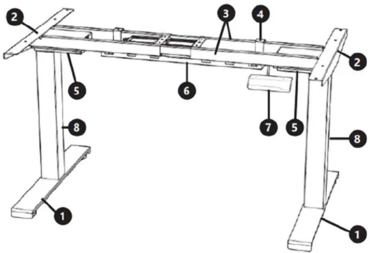
- Foot
- Side bracket
- Traverse
- Hook
- Control box
- Cable management tray
- Control panel
- Lifting column
APPLIANCE LOCATION
The device should always be used when positioned on an even, stable, clean, fireproof and dry surface, and be out of the reach of children and persons with limited mental and sensory functions.
ASSEMBLING THE APPLIANCE
To assemble the product you will need the following:
- spirit level,
- Allen key,
- drill,
• Phillips screwdriver.
After unpacking the set, check that it contains screws, spacers, and the following items:
 A (x1) A (x1) | 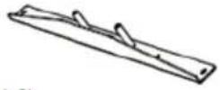 B (x2) B (x2) | 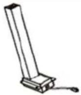 C (x2) C (x2) | 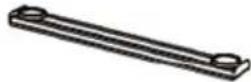 D (x2) D (x2) |
 E (x1) E (x1) | 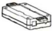 F (x1) F (x1) | 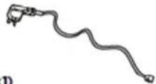 G (x1) G (x1) | 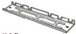 M (x1) M (x1) |
 I (x2) I (x2) | 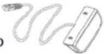 J (x1) J (x1) |
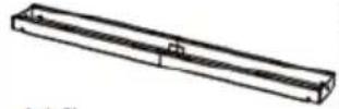
A - crossbar
B - side bracket
C - lifting column
D - foot
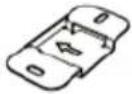
E - mounting plate
F - control box
G - plug
H - cable management tray
I - hook
J - control panel
1. Attaching the side supports:
- Put the worktop on the floor.
- Place the crossbar on the worktop and attach the side supports to its ends.
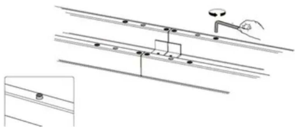
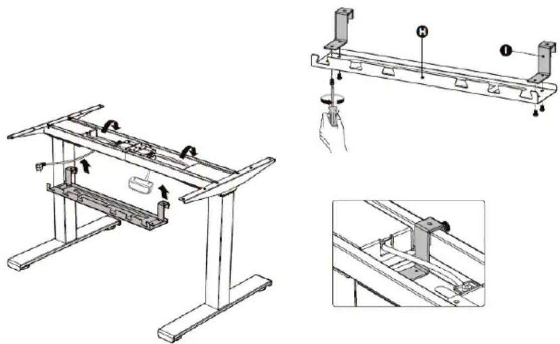
2. Frame adjustment:
- Loosen the hexagonal bolts securing the adjustable joint, but do not remove them.
natural_image
Technical line drawing of a mechanical assembly with a hand operating a lever and a small inset view of a component (no text or symbols)- Make sure the frame is placed in the centre of the worktop.
- Now, adjust the frame to the size of the table top.
- When adjusting the position of the frame, make sure it does not exceed the screen printing range on the crossbar.
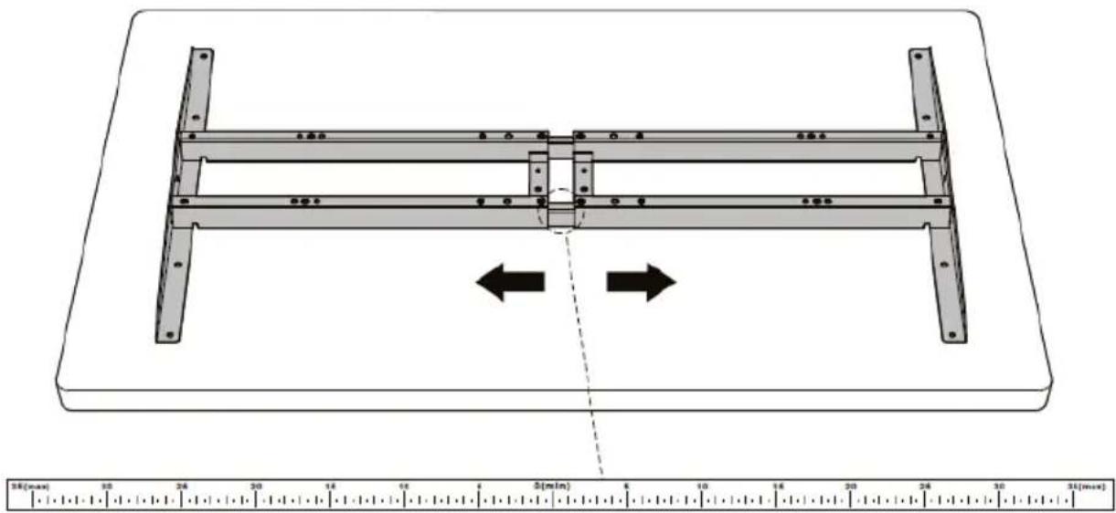
- Tighten the screws after completing the adjustment.
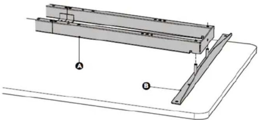
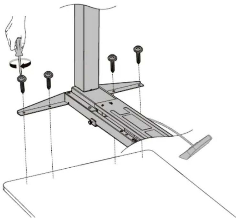
3. Drilling the mounting holes:
-
Use a drill to make mounting holes on the back of the table top.
-
The drill should be put successively in the 8 mounting holes on the side supports.
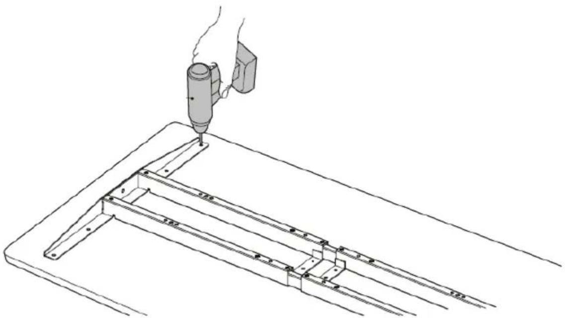
natural_image
Line drawing of a hand using a tool to lift a metal frame structure (no text or symbols)Please note: the depth of the mounting holes should be more than 10mm, and the diameter should be less than 3mm.
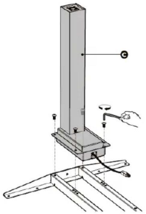
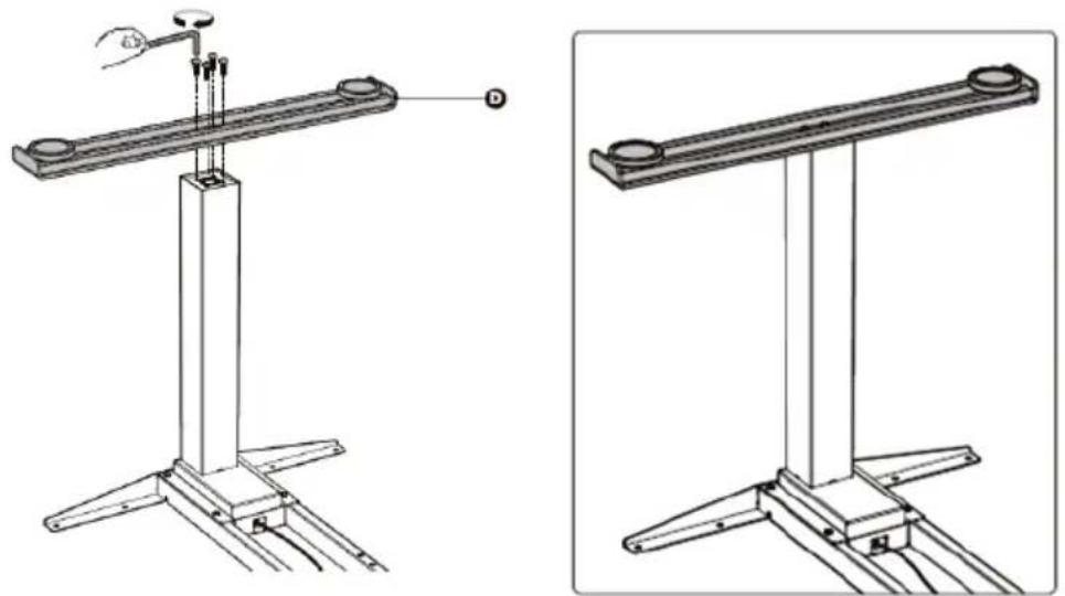
4. Mounting the lifting columns:
- Place a lifting column on one end of the crossbar pointing its head inwards.
- Make sure the mounting holes on the lifting column align with the holes on the crossbar.
- Attach the lifting column with 4 bolts using the Allen key.
- Repeat these steps to assemble the other lifting column.
natural_image
Technical line drawing of a vertical mechanical device with base mount and support structure (no text or symbols)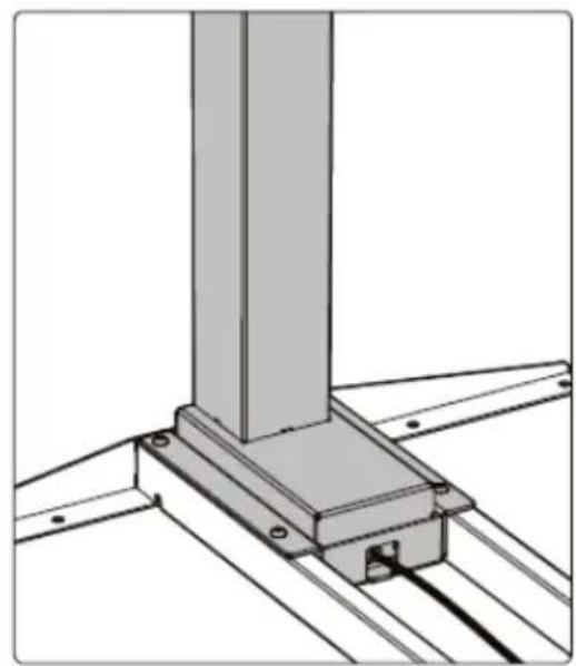
natural_image
Technical line drawing of a structural support bracket with mounting flanges (no text or symbols)5. Mounting the feet:
- Place the foot on the bottom of the lifting column.
- Align the mounting holes on the foot with the holes in the lifting column.
- Secure the foot with 4 screws using the Allen key.
- Repeat these steps to attach the other foot.
6. Mounting the mounting plate:
- Align the mounting holes in the mounting plate with the holes in the crossbar.
- Attach the mounting plate in the centre of the crossbar with 2 screws using a Phillips screwdriver. The mounting plate can be attached to both the right and left side.
Please note: The arrow on the mounting plate shows the direction of movement of the control box.

7. Control box assembly:
-
Turn the desk frame over so that the crossbar is facing up. It is recommended that at least two people participate in the turning the desk frame over.
-
Connect the wires, the control box, and the motor. Connect the two motor leads to the two sockets marked "M1" and "M2" (one on each side of the control box). Connect the control panel J cable to the socket marked "HS". Insert the plug into the "AC" socket.
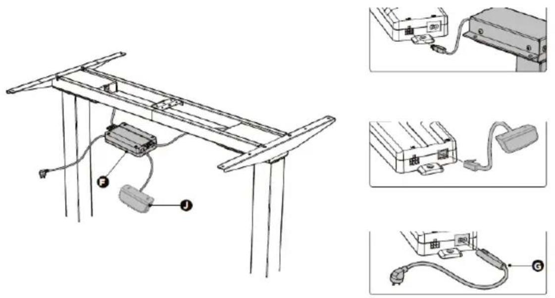
- Make sure the control box socket is facing up. There is no direct connection between the motor and the lifting columns.
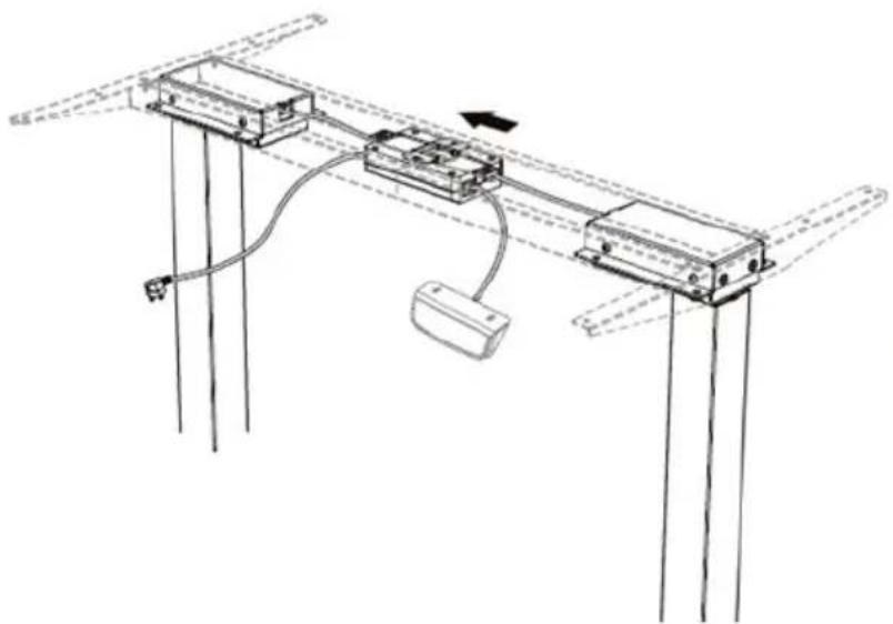
- The arrow on the mounting plate indicates the direction of movement of the control box.
Move the control box to the centre of the mounting plate.
natural_image
Technical line drawing of a mechanical assembly with mounting brackets and wiring (no text or symbols)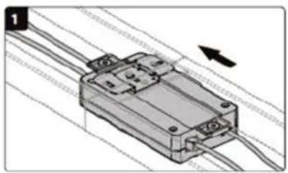
natural_image
Technical illustration of a mechanical assembly with wires and a directional arrow (no text or symbols)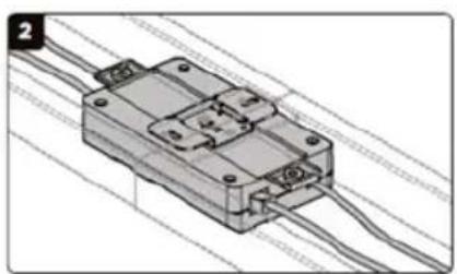
natural_image
Technical illustration of a mechanical component with wires, no visible text or symbols-
Installation of the cable tray:
-
Align the mounting holes in the hooks with the holes on the cable management tray.
-
Install the hooks on the tray with the 4 screws inserted from below using a Phillips screwdriver.
-
Attach the cable management tray to the crossbar in the position shown in the picture.
natural_image
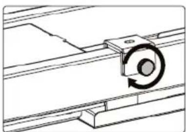
Technical line drawings of a mechanical assembly with structural supports and a hand holding a tool (no text or symbols present)- Tighten the knobs on the tray.
natural_image
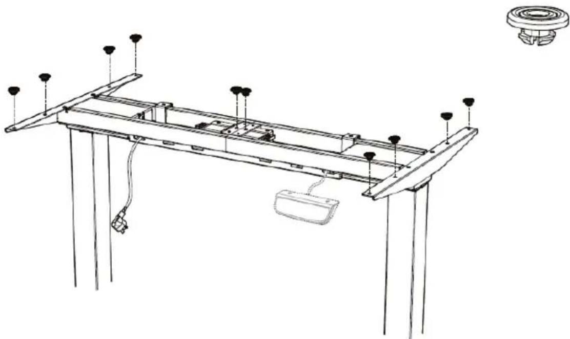
Technical line drawing of a mechanical assembly with a rotating component (no text or symbols)9. Worktop assembly:
- Attach the anti-vibration pads to the crossbar in the ten locations shown in the illustration.
natural_image
Technical line drawing of a structural frame with supports and a hanging component (no text or symbols)- Align the previously drilled holes with the holes on the crossbar. Insert and tighten the 4 screws from below.
- Repeat the same steps on the other side of the table top.
natural_image
Technical line drawing of a mechanical assembly with tools and components (no text or symbols)-
Attach the control panel to the worktop with 2 screws using a drill.
-
Stick the self-adhesive cable clip under the worktop to organize the cables.
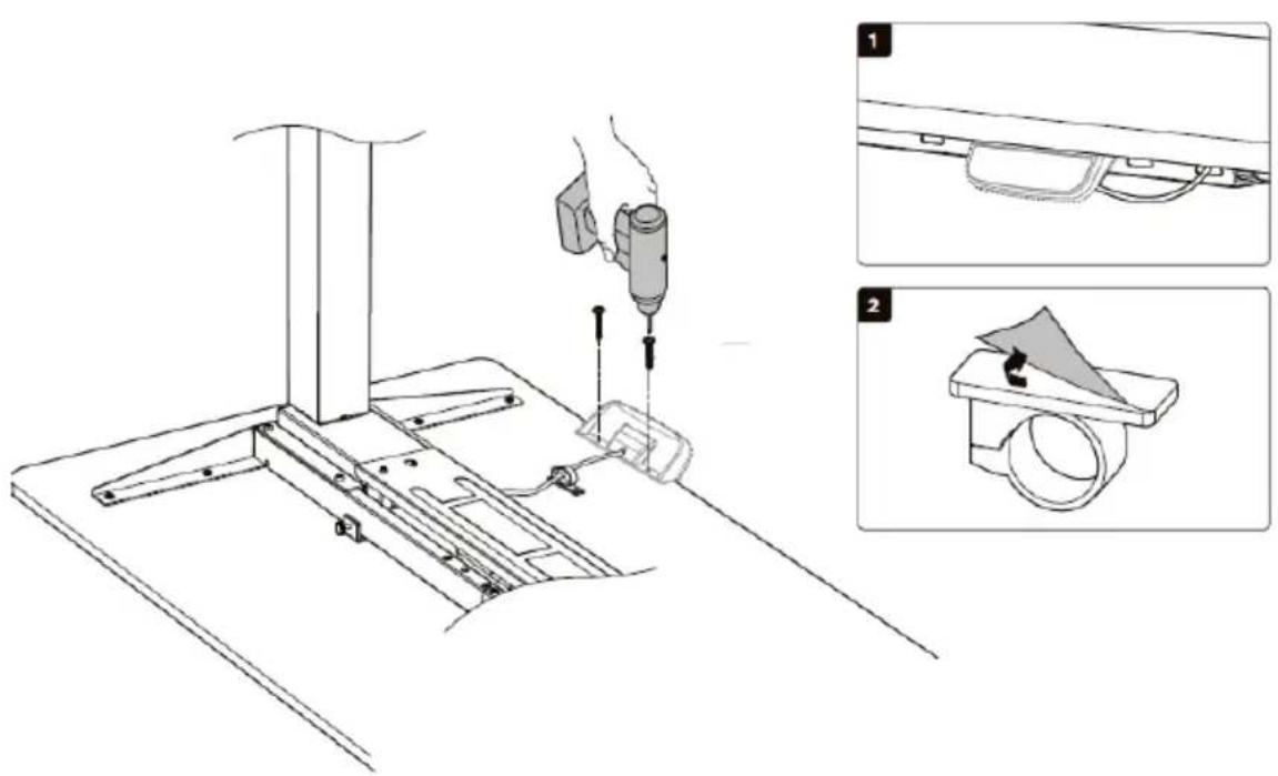
-
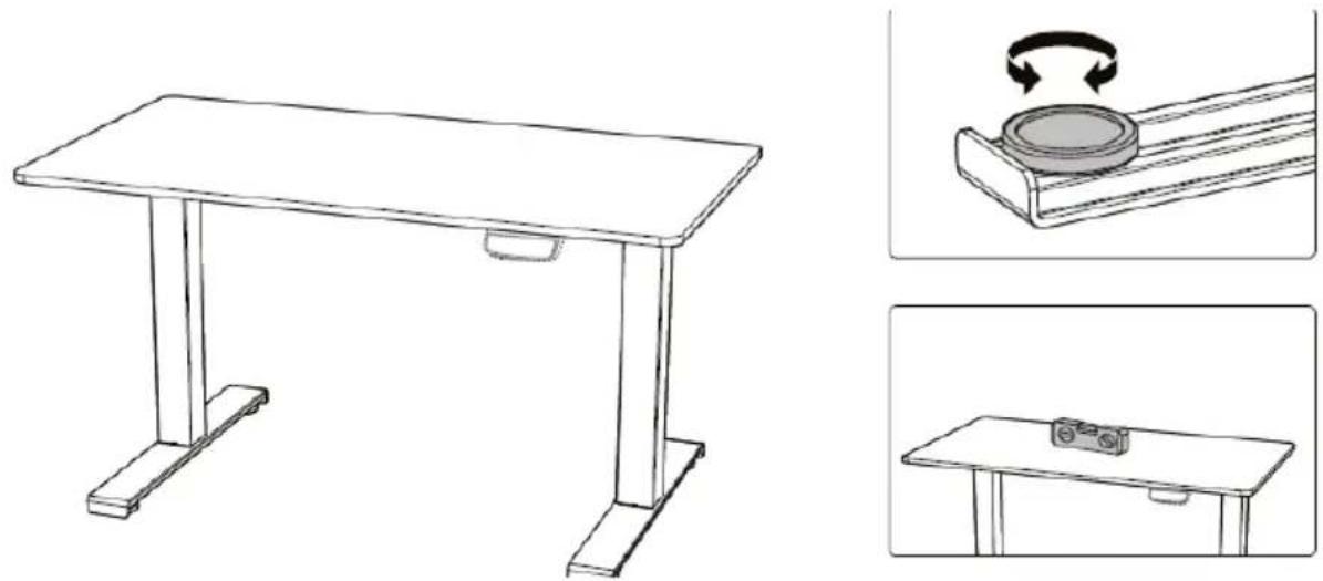
Using a spirit level, check that the table top is mounted evenly.
-
There are two adjustable spacers under each foot. If the floor is uneven, simply turn the spacer to adjust the level.
natural_image
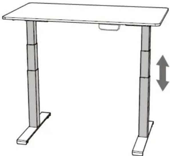
Line drawings of a simple wooden table with base supports and side supports, alongside three zoomed-in views showing mechanical components (no text or symbols)3.2. Device use
Height adjustment:
- Connect the plug to the mains socket.
- Adjust the height with the buttons on the panel.
natural_image
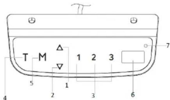
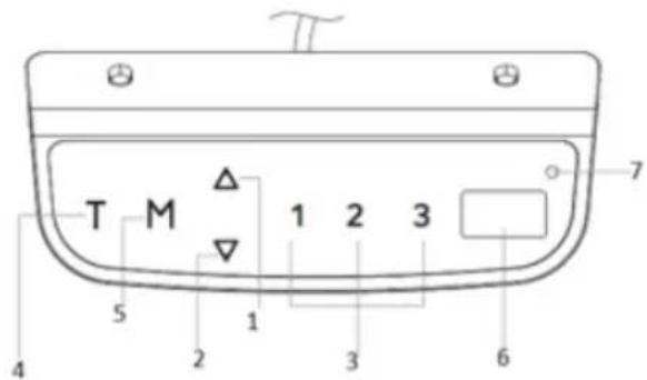
Simple line drawing of a two-legged desk with a horizontal shelf and vertical legs, showing a double-headed arrow indicating vertical displacement (no text or symbols)Control panel description
STAR_ATFE_06/STAR_ATFE_05
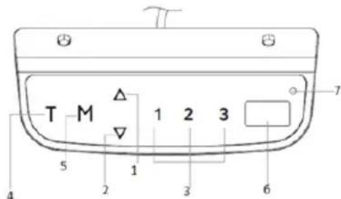
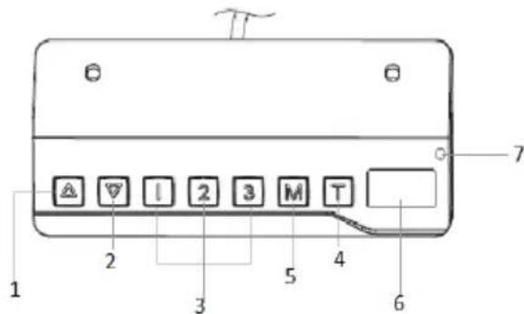
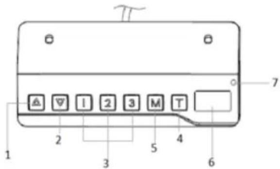
STAR_ATFE_07
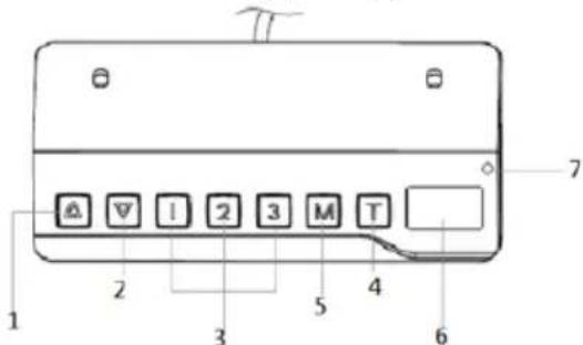
1 - lifting
2-lowering
3 - saved frame position
4 - timer
5 - memory function button/panel lock
6 - display
7 - lamp
APPLIES TO ALL MODELS:
Before the panel is used for the first time, it must first be reset:
-
Hold down the up and down arrows at the same time. The panel beeps and the display shows "rSr". The frame will begin lowering to the lowest level possible.
-
Hold the arrows down again until the panel beeps. The frame will raise slightly, and the display will show the current height.
Timer settings:
Using the timer, you can set the time after which the frame will automatically go up.
-
Press the T button. Each time you press it, the remaining time increases by 30 minutes. The maximum setting is 2 hours.
-
After the time is set, the display will flash for a moment, and then return to displaying the current height. The LED on the panel will come on.
-
After the set time has elapsed, the panel will beep 5 times.
-
To cancel the timer, press the T button several times until the LED goes out.
Panel memory:
You can save a given position (height) of the frame in the panel memory.
-
Press the M button.
-
When the display shows "S-" press a number: 1, 2, or 3.
-
To automatically set the memorized position of the frame, press the number under which the position was saved.
-
Press any button to stop the adjustment.
Panel Lock:
- Hold down the M button for 3 seconds.
- If the panel is locked, the display should read "----". Also, no operation can be performed using the panel.
- To unlock, hold the M button again for 3 seconds. The display will show the current height.
- The panel locks automatically after 1 minute of inactivity.
Unit change:
Pressing and holding the T button for 3 seconds you can toggle between the height reading in centimetres or inches.
Energy saving mode:
After 10 minutes of inactivity, the panel will automatically enter the energy saving mode. The panel will return to normal operation if you press any button.
Programming:
The user is able to program some of the parameters (S1-S7) as needed.
| Step 1:select the parameter | Step 2:description | Step3:adjust | Step4:record | Message | |
| S1 | In every case, to start the setting, hold down the M and T buttons simultaneously for about 5 seconds.The letter S with a number will appear on the display. Using arrows you can switch between parameters. | S1: setting the minimum height. Factory setting: 62.Range: 62–118 (cm)/24.4–46.4 ("). | 1.Press the M button to display the current saved value.2.Chang e using the arrows. | Press M to save. | The L-S change has been saved.L-F change has not been saved. |
| S2 | S2: setting the maximum height. Factory setting: 128.Range: 72-128 (cm)/28.3-50.4 ("). | The H-S change has been saved.H-F change has not been saved. | |||
| S3 | S3: Set the anti-collision sensitivity (move up). Factorysetting: 4. Range: 0 - 8. | S-S change has beensaved. S-F change has not been saved. | |||
| S4 | S4: Setting the anti-collision (downward motion) sensitivity. Factory setting: 4 .. Range: 0 - 8. | S-S change has been saved. S-F change has not been saved. | |||
| S5 | S5: Set the anti-collision sensitivity (spatial orientation). Factory setting: 4. Range: 0 - 8. | S-S change has been saved. S-F change has not been saved. | |||
| S6 | S6: setting the worktop thickness. Factory setting: 0.0. Range: 0-5 (cm)/0-1.9 ("). | T-S change has been saved. T-F change has not been saved. | |||
| S7 | S7: Activate/deactivate the locking function. | A-S change has | |||
| Range: 0 (disabled) -1 (enabled). | been saved. A-F change has not been saved. |
The display can show the changed value with a delay.
To exit the programming mode, press the T button.
After 10 seconds of inactivity, the panel will automatically return to normal operation.
3.3. Cleaning and maintenance
a) Always unplug the device before cleaning it.
b) Store the unit in a dry, cool place, free from moisture and direct exposure to sunlight.
c) Do not spray the device with a water jet or submerge it in water.
d) The device must be regularly inspected to check its technical efficiency and spot any damage.
e) Use a soft cloth for cleaning.
f) Use a soft, damp cloth for cleaning.
g) Do not use sharp and/or metal objects for cleaning (e.g. a wire brush or a metal spatula) because they may damage the surface material of the appliance.
PROBLEM SOLVING
APPLIES TO ALL MODELS:
| Problem | Description |
| E01/E06/E07/E12/E22 | There is a problem with network - pull the plug out of the socket. If the problem persists, replace the control box. |
| HOT | HOT Overheating - Stop working for approximately 18 minutes and let the device cool down. |
| E02 | E02 The columns don’t rise evenly - reset the system. |
| E04 | E04 The panel doesn’t work - check the connection, disconnect and reconnect the panel. |
| E05 | E05 The system has recognized a risk of collisionwith another object - remove objects interfering with the adjustment. |
| E08 | Danger of collision.Control box problem - the control box is probably not positioned correctly. Check that it is firmly attached to the frame and it is on a level surface, and that it is not the fault of the cables - if they are not placed in an orderly manner, they may cause the box to move. |
| E11/E21E13/23E14/24 | Disconnecting the cables powering of the lifting columns - check the connection.Damage to the lifting columns cables - check and replace.E11/13/14 indicates socket M1 error.E21/23/24 indicates M2 slot error. |
| E15/E25 | Short circuit - replace elements that have shorted and are no longer usable.E15 indicates a short circuit in socket M1.E25 indicates a short circuit in socket M2. |
| E16/E26E18/E28 | Overload - remove items from the table top. |
| E17/E27 | The frame moves in wrong direction - check lifting column wiring connection and replace if necessary.E17 indicates an error in socket M1.E27 indicates an error in socket M2. |
| E42 | Unable to read the memory - disconnect and reconnect the power cord. If the problem persists, replace the control box. |
| E43 | Collision detection system failure - replace the control box. |
Dane techniczne
natural_image
Technical diagram of a mechanical assembly with labeled parts A and B (no text or symbols beyond labels)2. Regulacja ramy:
natural_image
Technical line drawing of a mechanical assembly with mounting brackets and a hand operating a tool (no text or symbols)natural_image
Line drawing of a hand using a tool to lift a mechanical component on a flat base (no text or symbols)natural_image
Technical diagram of a vertical mechanical device with mounting base and support structure, showing hand operating arm (no text or symbols)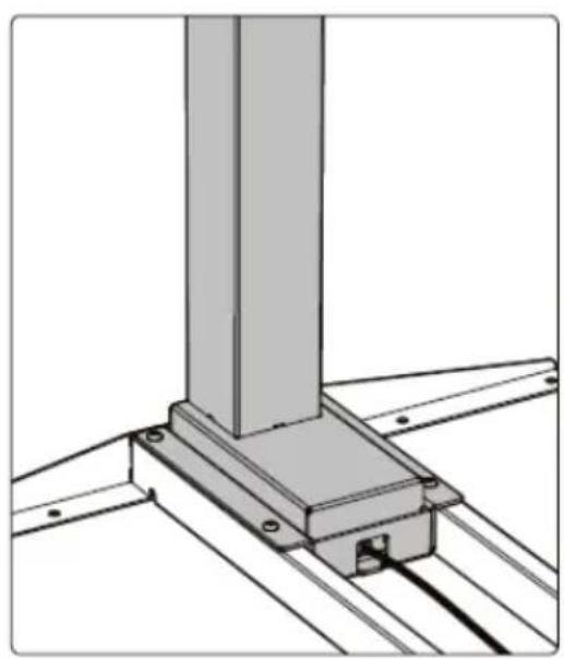
natural_image
Technical line drawing of a structural support bracket with mounting flanges (no text or symbols)5. Montaż stopek:
natural_image
Technical line drawing of a mechanical apparatus with a vertical support and base mount (no text or symbols)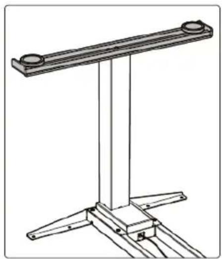
natural_image
Technical line drawing of a mechanical support structure with two circular components and three triangular supports (no text or symbols)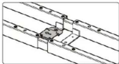
natural_image
Pure technical line drawing of a mechanical assembly with no text, numbers, or symbols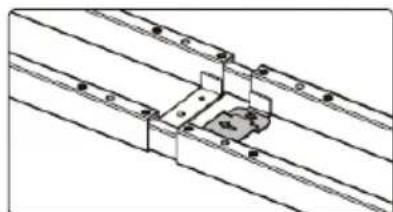
natural_image
Technical line drawing of a mechanical assembly with mounting brackets and fasteners (no text or symbols)natural_image
Technical line drawing of a mechanical assembly with mounting brackets and wiring (no text or symbols)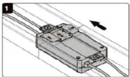
natural_image
Technical illustration of a mechanical component with wires and a directional arrow (no text or symbols)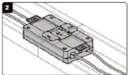
natural_image
3D diagram of a mechanical component with wires and mounting holes (no text or symbols)natural_image
Technical line drawing of a mechanical assembly with a rotating component (no text or symbols)9. Montaż blatu:
natural_image
Technical line drawing of a structural frame with supports and a hanging component (no text or symbols)natural_image
Technical line drawing of a mechanical assembly with tools and components (no text or symbols)natural_image
Line drawing of a simple wooden table with two legs and a side shelf (no text or symbols)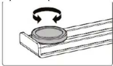
natural_image
Diagram of a rotating mechanical component with a circular base and curved arrows indicating rotation (no text or symbols)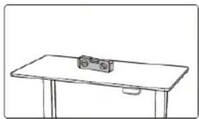
natural_image
Simple line drawing of a table with a small object on top (no text or symbols)natural_image
Simple line drawing of a two-legged desk with a horizontal shelf and vertical legs, showing a double-headed arrow indicating vertical displacement (no text or symbols)OPIS PANELU STEROWANIA:
STAR_ATFE_06/STAR_ATFE_05
STAR_ATFE_07
2. Nastavení rámu:
natural_image
Diagram of musical notation on a track with a hand holding a staff, showing alignment and movement (no text or symbols)natural_image
Technical line drawing of a mechanical assembly with a tool and base plate (no text or symbols)natural_image
Technical diagram of a vertical mechanical device with base, legs, and mounting bracket (no text or symbols)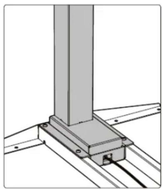
natural_image
Technical line drawing of a structural support bracket with mounting holes and beams (no text or symbols)5. Montáž patek:
natural_image
Technical line drawing of a mechanical testing apparatus with a vertical column and base, no text or symbols present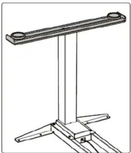
natural_image
Technical line drawing of a mechanical support structure with two vertical supports and circular components (no text or symbols)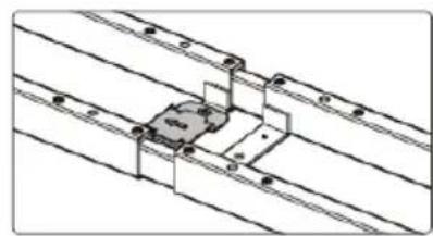
natural_image
Pure technical diagram of a mechanical assembly with parallel lines and no visible text or symbols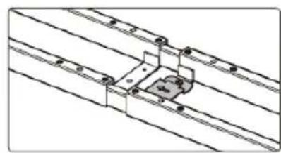
natural_image
Technical line drawing of a mechanical assembly with parallel lines and mounting holes (no text or symbols)natural_image
Technical line drawing of a mechanical assembly with vertical supports and connected components (no text or symbols)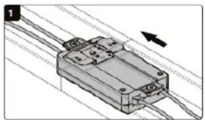
natural_image
3D diagram of a mechanical component with wires and mounting holes, no visible text or symbols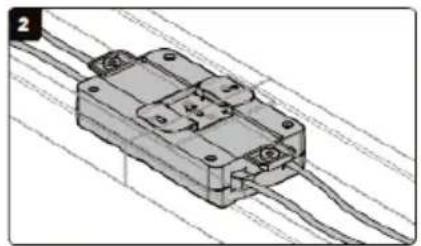
natural_image
3D diagram of a mechanical component with wires and mounting holes (no text or symbols)natural_image
Technical line drawing of a mechanical assembly with a circular component and base plate (no text or symbols)natural_image
Technical line drawing of a structural frame with supports and a hanging component (no text or symbols)natural_image
Technical line drawing of a mechanical assembly with multiple screwdrivers and a vertical support (no text or symbols)natural_image
Line drawings of a simple wooden table with base supports and side supports, alongside three zoomed-in views showing the same table and a circular component being handled (no text or symbols present)natural_image
Simple line drawing of a two-legged desk with vertical legs and a horizontal shelf, showing a double-headed arrow indicating vertical displacement (no text or symbols)POPIS OVLÁDACÍHO PANELU:
STAR_ATFE_06/STAR_ATFE_05
STAR_ATFE_07
natural_image
Technical line drawing of a mechanical assembly with a hand operating a bracket and a close-up inset showing a small component (no text or symbols)natural_image
Line drawing of a hand using a tool to lift a mechanical component on a wooden base (no text or symbols)natural_image
Technical line drawing of a mechanical device with a vertical support and labeled component (no text or symbols present)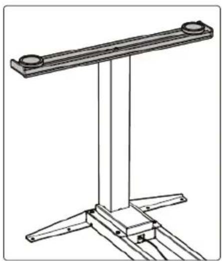
natural_image
Technical line drawing of a mechanical support structure with two circular components and three triangular supports (no text or symbols)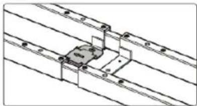
natural_image
Technical line drawing of a mechanical assembly with parallel lines and a central component (no text or symbols)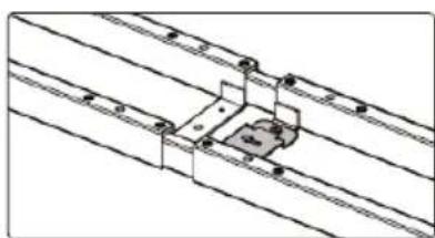
natural_image
Technical line drawing of a mechanical assembly with parallel lines and a central bracket (no text or symbols)natural_image
Technical line drawing of a mechanical assembly with mounting brackets and wiring (no text or symbols)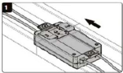
natural_image
3D diagram of a mechanical component with wires and mounting holes, no visible text or symbols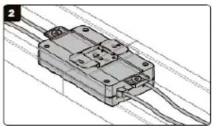
natural_image
3D diagram of a mechanical component with wires and mounting holes (no text or symbols)natural_image
Technical line drawings of a mechanical assembly with structural supports and a hand tool (no text or symbols)natural_image
Technical line drawing of a mechanical assembly with a rotating component (no text or symbols)9. Montage du plan:
natural_image
Technical line drawing of a structural frame with vertical supports and mounting points (no text or symbols)natural_image
Technical line drawing of a mechanical assembly with tools and components (no text or symbols)natural_image
Line drawings of a simple table with supports and a circular component, shown in three views: top-down, side-up, and front-down (no text or symbols)natural_image
Simple line drawing of a two-legged desk with vertical legs and a horizontal shelf, showing a double-headed arrow indicating vertical displacement (no text or symbols)natural_image
Technical line drawing of a musical instrument with tuning pegs and staff (no text or symbols)natural_image
Technical diagram of a mechanical frame assembly with two vertical supports and a central horizontal bar, showing dimension annotations (no text labels or symbols)natural_image
Line drawing of a hand using a tool to lift a metal frame structure (no text or symbols)natural_image
Technical line drawing of a mechanical device with a vertical column and base supports, showing no text or symbols.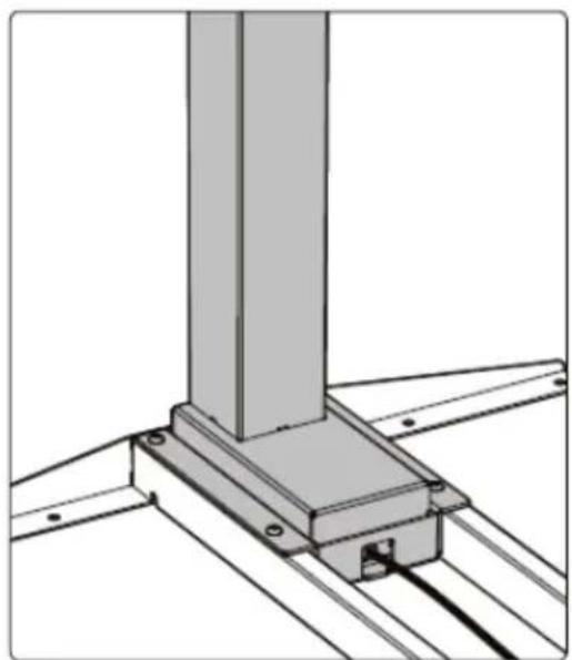
natural_image
Technical line drawing of a structural support bracket with mounting flanges (no text or symbols)natural_image
Technical line drawings of a mechanical support structure with base supports and a dial indicator (no text or symbols)natural_image
Technical line drawing of a mechanical assembly with supports and a central component (no text or symbols)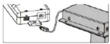
natural_image
Diagram showing two connected devices with a cable, no text or symbols present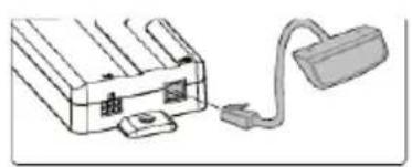
natural_image
Simple line drawing of a device with a fuse and connector (no text or symbols)
natural_image
Diagram of a cable with a connector and plug, no text or symbols presentnatural_image
Technical diagram showing two views of a mechanical assembly with connected components and wiring (no text or symbols present)natural_image
Technical line drawings of a mechanical assembly with structural supports and a hand holding a tool (no text or symbols present)natural_image
Technical line drawing of a mechanical assembly with a rotating component (no text or symbols)natural_image
Technical line drawing of a structural frame with supports and a hanging device (no text or symbols)natural_image
Technical line drawing of a mechanical assembly with tools and components (no text or symbols)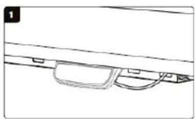
natural_image
Simple line drawing of a mechanical component with no text or symbols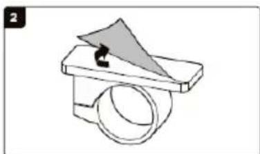
natural_image
Simple line drawing of a mechanical component with a triangular load and cylindrical body (no text or symbols)natural_image
Line drawings of a simple wooden table with base supports and side supports, alongside two views showing a circular component being turned by a rotating arm (no text or symbols present)natural_image
Simple line drawing of a two-legged desk with a horizontal shelf and vertical legs, showing a double-headed arrow indicating vertical displacement (no text or symbols)J - panel de control
2. Ajuste del marco:
natural_image
Technical line drawing of a mechanical assembly with mounting holes and a hand holding a tool (no text or symbols)natural_image
Line drawing of a hand using a tool to lift a metal frame structure (no text or symbols)natural_image
Technical diagram of a vertical support structure with mounting base and wiring, no visible text or symbols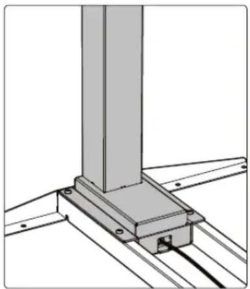
natural_image
Technical line drawing of a structural support bracket with mounting flanges (no text or symbols)natural_image
Technical line drawing of a mechanical scale with base, legs, and support components (no text or symbols)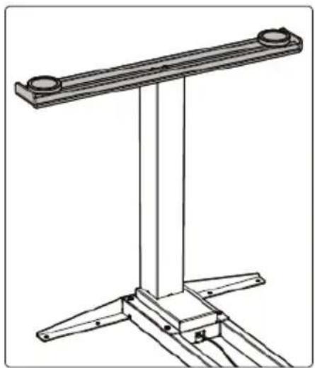
natural_image
Technical line drawing of a mechanical support structure with two circular components and three triangular supports (no text or symbols)natural_image
Technical line drawing of a mechanical assembly with rods, pulleys, and a central component (no text or symbols)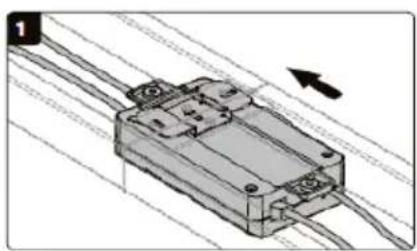
natural_image
Mechanical component with wiring and mounting holes, no visible text or symbols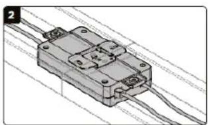
natural_image
3D diagram of a mechanical component with wires and mounting holes (no text or symbols)natural_image
Technical line drawings of a mechanical assembly with structural supports and a close-up inset showing a hand holding a tool (no text or symbols present)natural_image
Technical line drawing of a mechanical assembly with a rotating component (no text or symbols)natural_image
Technical line drawing of a structural frame with supports and a hanging component (no text or symbols)natural_image
Technical line drawing of a mechanical assembly with multiple screw fasteners and a vertical support (no text or symbols)natural_image
Line drawing of a simple wooden table with two legs and a side shelf (no text or symbols)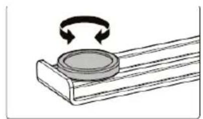
natural_image
Diagram of a rotating mechanical component with curved arrows indicating rotation (no text or symbols)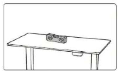
natural_image
Simple line drawing of a wooden table with a small object on top (no text or symbols)natural_image
Simple line drawing of a two-legged desk with a horizontal shelf and vertical legs, showing a double-headed arrow indicating vertical displacement (no text or symbols)For the disposal of the device please consider and act according to the national and local rules and regulations.
CONTACT
expondo Polska sp. z o.o. sp. k.