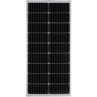
MSMO-75 - Solar panel Mestic - Free user manual and instructions
Find the device manual for free MSMO-75 Mestic in PDF.


| Product type | Photovoltaic solar panel |
| Brand | Mestic |
| Model | MSMO-75 |
| Rated power | 75 W |
| Rated voltage | 12 V |
| Junction box | Yes, with positive and negative terminals |
| Cables included | Yes, pre-wired in the junction box |
| Mounting brackets | Included |
| Roof penetration | Included |
| Installation method | Fixing with adhesive or glue on flat surface |
| Possible connections | In series (24 V) or in parallel (12 V) |
| System compatibility | With battery and charge controller |
| Installation orientation | Horizontal or vertical, junction box at top |
| Maintenance | Occasional cleaning of the glass |
| Cleaning | Soft cloth with mild detergent and water (50%) |
| Back protection | Protective film that must not be damaged |
| Recycling | Yes, compliant with WEEE directive (2012/19/EU) |
| Standards | EC directives 2014/30/EU and 2014/35/EU |
| Usage | Standalone solar system for charging batteries |
Frequently Asked Questions - MSMO-75 Mestic
User questions about MSMO-75 Mestic
0 question about this device. Answer the ones you know or ask your own.
Ask a new question about this device
Download the instructions for your Solar panel in PDF format for free! Find your manual MSMO-75 - Mestic and take your electronic device back in hand. On this page are published all the documents necessary for the use of your device. MSMO-75 by Mestic.
USER MANUAL MSMO-75 Mestic
natural_image
Close-up of a grid of black rectangular panels with white vertical lines, no text or symbols visible.



FR
| MSMO-75 | MSMO-100 | MSMO-120 | MSMO-140 | MSMO-160 | MSMO-180 | MSMO-200 | |
| Maximaal vermogen (Pmax) | 75W | 100W | 120W | 140W | 160W | 180W | 200W |
| Spanning bij Pmax (Vmpp) | 18.56 V | 23.2 V | 19.14 V | 22.62 V | 24.36 V | 24.36 V | 24.36 V |
| Stroom bij Pmax (Impp) | 4.04 A | 4.31 A | 6.27 A | 6.19 A | 6.57 A | 7.39 A | 8.21 A |
| Open klemspanning (Voc) | 21.76 V | 27.2 V | 22.11 V | 26.13 V | 28.14 V | 28.14 V | 28.14 V |
| Kortsluitstroom (Isc) | 4.28 A | 4.57 A | 6.65 A | 6.56 A | 6.96 A | 7.83 A | 8.70 A |
Serie- en parallelschakeling
natural_image
Pure technical line drawing of a mechanical component without any text, numbers, or symbols- Junction box
- Cables
- Roof penetration
- Mounting bracket
natural_image
Close-up of a solar panel with grid lines and metallic contacts (no text or symbols visible)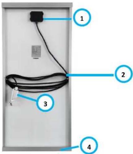
| MSMO-75 | MSMO-100 | MSMO-120 | MSMO-140 | MSMO-160 | MSMO-180 | MSMO-200 | |
| Maximum power (Pmax) | 75W | 100W | 120W | 140W | 160W | 180W | 200W |
| Voltage at Pmax (Vmpp) | 18.56 V | 23.2 V | 19.14 V | 22.62 V | 24.36 V | 24.36 V | 24.36 V |
| Current at Pmax (Impp) | 4.04 A | 4.31 A | 6.27 A | 6.19 A | 6.57 A | 7.39 A | 8.21 A |
| Open-circuit voltage (Voc) | 21.76 V | 27.2 V | 22.11 V | 26.13 V | 28.14 V | 28.14 V | 28.14 V |
| Short-circuit current (Isc) | 4.28 A | 4.57 A | 6.65 A | 6.56 A | 6.96 A | 7.83 A | 8.70 A |
General instructions
Before using this appliance, read the operating instructions carefully.
Keep the manual for future use.
Assembly
Note: as soon as the solar panel is exposed to light or sunlight, the terminals in the junction box are energised. To avoid short circuits when mounting and connecting the solar panels, you can turn the panels away from the light or cover them so that they do not produce electricity during the assembly process. Remove the cover when the connection is complete.
General assembly instructions:
- Always mount the panel on a straight, flat surface. Do not bend or twist the panel.
- Never try to disassemble the panel.
- Avoid drilling or welding in the frame wherever possible.
- Do not use sharp metal tools or other objects that may scratch the surface of the panel.
- Install the panel horizontally or vertically with the junction box at the top.
- Choose a location for the panel with as little shade as possible. Keep in mind that if the solar panel is shaded, the power output will decrease.
- Mount the panel so that air can circulate freely around it.
- The supplied cables are already connected for you in the junction box. Do not disconnect it or swap the plus and minus terminals.
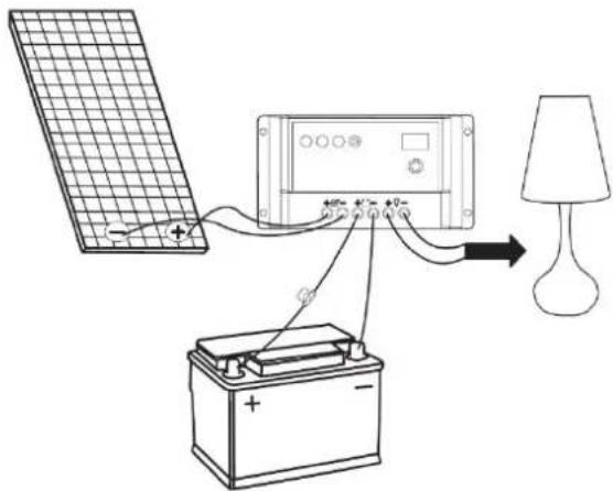
- Always connect the battery to the charge controller before connecting the solar module.
- Check the system regularly to make sure it is functioning normally.
Determining location:
- Determine the location for installing the solar panel, by placing it in the desired spot.
- Mark this location and check that there is enough space around the panel.
- Plan the laying of your wiring before proceeding with the installation.
Mounting:
-
Once you have checked your mounting location, you fix the panels to the desired location with the brackets, using appropriate mounting sealant or glue. Follow the instructions on the packaging of the respective product.
-
Note: make sure the surface on which the brackets are placed is clean, free of grease and dust, and dry. We recommend roughing up the surface first before degreasing it thoroughly. Sealant or glue in a clean, dry environment.
- Make sure the adhesive forms a good seal on the mounting surface by applying an even, continuous strip in the ridges at the bottom of the mounting brackets. The volume of the sealant or glue should be greater than the ridges.
- Evenly and carefully press the panel down at the selected location.
- Remove excess sealant or glue.
- Let the sealant or glue dry thoroughly. Follow the instructions on the packaging of the respective product for this.
- Note: preferably double-check the dimensions of the panel with the mounting brackets and the chosen location to avoid errors. The sealant or adhesive is very difficult to remove once applied.
Routing cables:
- Before you can install the roof penetration, find the most suitable location for your power cables to go through the roof. Before drilling, check again that there are no other cables, pipes, etc. at the place you want to drill.
- Once you are sure what your entry point is, drill holes of the right size.
- Check that the cables are through the cable holes in the roof penetration and route the cables through holes drilled in the roof to the desired location.
- Note: make sure the surface on which the roof penetration is placed is clean, free of grease and dust, and dry. We recommend roughing up the surface first before degreasing it thoroughly.
- Apply an even, continuous strip of sealant or glue to the underside of the cable penetration and attach it to the mounting surface, ensuring that the drilled holes are completely covered.
- After the sealant or glue has cured, you can also apply a sealant to ensure a watertight seal around the cable penetration.
Note: a solar panel must be connected to a battery system via a charge controller. For correct installation, follow the instructions supplied with the product.
Series and parallel connection
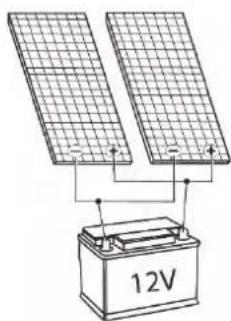
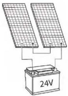
If more than one panel is used, they can be connected either in series or in parallel.
natural_image
Diagram of two solar panels connected to a 12V battery (no text or symbols on the components)Parallel:
To connect 2 solar panels in a 12 V system, connect the panels in parallel by connecting the plus to the plus and the minus to the minus.
Series:
To connect 2 solar panels in a 24 V system, connect the panels in series by connecting the plus of one panel to the minus of the next panel.
natural_image
Pure technical line drawing of a mechanical bracket or bracket (no text or symbols)Plus and minus connection view:
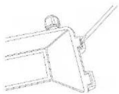
Open the junction box by gently loosening the tabs with a screwdriver.
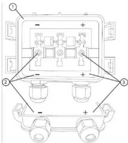
- Junction box
- Negative pole and connection
- Positive pole and connection
Please note: The supplied cables have already been connected for you in the connection box. Do not disconnect this and do not swap the plus and minus connections.
Maintenance
- Normally, normal rainfall and wind are enough to keep the module glass clean. If necessary, you can clean the glass with a soft cloth with a mild detergent and 50% water.
- Note: do not damage the protective film on the back of the solar panels.

Recycling
This product bears the selective sorting symbol for waste electrical and electronic equipment This means that this product must be handled pursuant to European Directive (2012/19/EU) in order to be recycled or dismantled to minimize its impact on the environment. For further information, please contact your local or regional authorities. Electronic products not included in the selective sorting process are potentially dangerous for the environment and human heath due to the presence of hazardous substances.
Declaration of conformity
Hereby EURO ACCESSOIRES declares that the device MSMO-75/-100/-120/-140/-160/-180/-200 applies all basic requirements and other relevant regulations listed in the European directive for electromagnetic compatibility (2014/30/EU) and low voltage directive (2014/35/EU). If you require a full declaration of conformity, you can contact the address listed on the backside of this manual.
DEUTSCH
natural_image
Close-up of a solar panel with grid lines and rectangular panels (no text or symbols visible)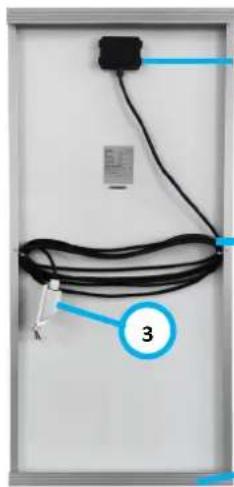
natural_image
Close-up of a black cable with a connector and label '3' pointing to it, mounted on a white panel (no readable text or symbols beyond labels)
flowchart
graph TD
    A["1"] --> B["2"]
    B --> C["4"]
| MSMO-75 | MSMO-100 | MSMO-120 | MSMO-140 | MSMO-160 | MSMO-180 | MSMO-200 | |
| Maximale Leistung (Pmax) | 75W | 100W | 120W | 140W | 160W | 180W | 200W |
| Spannung bei Pmax (Vmpp) | 18.56 V | 23.2 V | 19.14 V | 22.62 V | 24.36 V | 24.36 V | 24.36 V |
| Strom bei Pmax (Impp) | 4.04 A | 4.31 A | 6.27 A | 6.19 A | 6.57 A | 7.39 A | 8.21 A |
| Leerlaufspannung (Voc) | 21.76 V | 27.2 V | 22.11 V | 26.13 V | 28.14 V | 28.14 V | 28.14 V |
| Kurzschlussstrom (Isc) | 4.28 A | 4.57 A | 6.65 A | 6.56 A | 6.96 A | 7.83 A | 8.70 A |
Allgemeine Hinweise
natural_image
Diagram of two solar panels connected to a 12V battery, no text or symbols presentParallel:
natural_image
Pure technical line drawing of a mechanical component without any text, numbers, or symbolsnatural_image
Close-up of a black solar panel with grid lines (no text or symbols visible)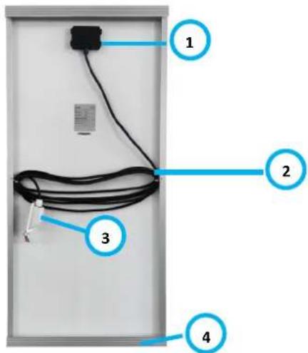
| MSMO-75 | MSMO-100 | MSMO-120 | MSMO-140 | MSMO-160 | MSMO-180 | MSMO-200 | |
| Puissance maximum (Pmax) | 75W | 100W | 120W | 140W | 160W | 180W | 200W |
| Tension à Pmax (Vmpp) | 18.56 V | 23.2 V | 19.14 V | 22.62 V | 24.36 V | 24.36 V | 24.36 V |
| Courant à Pmax (Impp) | 4.04 A | 4.31 A | 6.27 A | 6.19 A | 6.57 A | 7.39 A | 8.21 A |
| Tension de circuit ouvert (Voc) | 21.76 V | 27.2 V | 22.11 V | 26.13 V | 28.14 V | 28.14 V | 28.14 V |
| Courant de court-circuit (Isc) | 4.28 A | 4.57 A | 6.65 A | 6.56 A | 6.96 A | 7.83 A | 8.70 A |
natural_image
Pure technical line drawing of a mechanical component without any text, numbers, or symbolsnatural_image
Close-up of a solar panel with grid lines and uniform square photovoltaic cells (no text or symbols visible)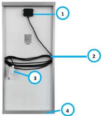
| MSMO-75 | MSMO-100 | MSMO-120 | MSMO-140 | MSMO-160 | MSMO-180 | MSMO-200 | |
| Potencia máxima (Pmax) | 75W | 100W | 120W | 140W | 160W | 180W | 200W |
| Tensión en Pmax (Vmpp) | 18.56 V | 23.2 V | 19.14 V | 22.62 V | 24.36 V | 24.36 V | 24.36 V |
| Corriente en Pmax (Impp) | 4.04 A | 4.31 A | 6.27 A | 6.19 A | 6.57 A | 7.39 A | 8.21 A |
| Tensión de circuito abierto (Voc) | 21.76 V | 27.2 V | 22.11 V | 26.13 V | 28.14 V | 28.14 V | 28.14 V |
| Courant de court-circuit (Isc) | 4.28 A | 4.57 A | 6.65 A | 6.56 A | 6.96 A | 7.83 A | 8.70 A |
natural_image
Pure technical line drawing of a mechanical bracket or bracket (no text or symbols)natural_image
Close-up of a solar panel with grid lines and metallic contacts (no text or symbols visible)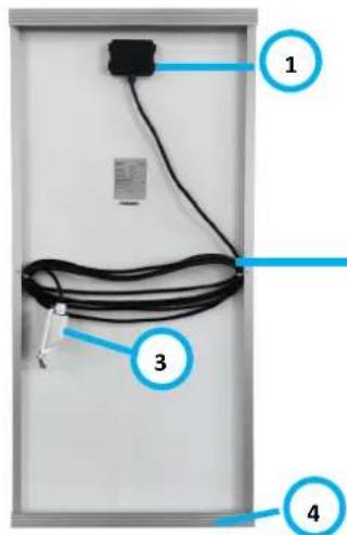
| MSMO-75 | MSMO-100 | MSMO-120 | MSMO-140 | MSMO-160 | MSMO-180 | MSMO-200 | |
| Potenza massima (Pmax) | 75W | 100W | 120W | 140W | 160W | 180W | 200W |
| Tensione a Pmax (Vmpp) | 18.56 V | 23.2 V | 19.14 V | 22.62 V | 24.36 V | 24.36 V | 24.36 V |
| Corrente a Pmax (Impp) | 4.04 A | 4.31 A | 6.27 A | 6.19 A | 6.57 A | 7.39 A | 8.21 A |
| Tensione a circuito aperto (Voc) | 21.76 V | 27.2 V | 22.11 V | 26.13 V | 28.14 V | 28.14 V | 28.14 V |
| Corrente di cortocircuito (Isc) | 4.28 A | 4.57 A | 6.65 A | 6.56 A | 6.96 A | 7.83 A | 8.70 A |
Istruzioni generali
natural_image
Pure technical line drawing of a mechanical bracket or bracket (no text or symbols)natural_image
Close-up of a solar panel with grid lines and metallic contacts (no text or symbols visible)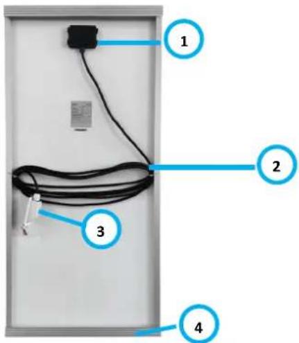
| MSMO-75 | MSMO-100 | MSMO-120 | MSMO-140 | MSMO-160 | MSMO-180 | MSMO-200 | |
| Maksimal effekt (Pmax) | 75W | 100W | 120W | 140W | 160W | 180W | 200W |
| Spænding ved Pmax (Vmpp) | 18.56 V | 23.2 V | 19.14 V | 22.62 V | 24.36 V | 24.36 V | 24.36 V |
| Strøm ved Pmax (Impp) | 4.04 A | 4.31 A | 6.27 A | 6.19 A | 6.57 A | 7.39 A | 8.21 A |
| Åben kredsløbsspænding (Voc) | 21.76 V | 27.2 V | 22.11 V | 26.13 V | 28.14 V | 28.14 V | 28.14 V |
| Kortslutningsstrøm (Isc) | 4.28 A | 4.57 A | 6.65 A | 6.56 A | 6.96 A | 7.83 A | 8.70 A |
Generelle instruktioner
natural_image
Pure technical line drawing of a mechanical component without any text, numbers, or symbolsnatural_image
Close-up of a solar panel with grid lines and metallic contacts (no text or symbols visible)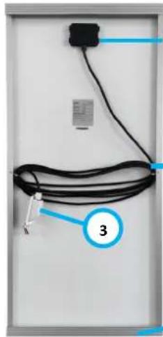
natural_image
Close-up of a black cable with a labeled connector (number 3) and a small electronic device on top (no text or symbols on the cable itself)1
2
4
| MSMO-75 | MSMO-100 | MSMO-120 | MSMO-140 | MSMO-160 | MSMO-180 | MSMO-200 | |
| Maximal effekt (Pmax) | 75W | 100W | 120W | 140W | 160W | 180W | 200W |
| Spänning vid Pmax (Vmpp) | 18.56 V | 23.2 V | 19.14 V | 22.62 V | 24.36 V | 24.36 V | 24.36 V |
| Ström vid Pmax (Impp) | 4.04 A | 4.31 A | 6.27 A | 6.19 A | 6.57 A | 7.39 A | 8.21 A |
| Öppen kretsspänning (Voc) | 21.76 V | 27.2 V | 22.11 V | 26.13 V | 28.14 V | 28.14 V | 28.14 V |
| Kortslutningsström (Isc) | 4.28 A | 4.57 A | 6.65 A | 6.56 A | 6.96 A | 7.83 A | 8.70 A |
natural_image
Pure technical line drawing of a mechanical component without any text, numbers, or symbolsnatural_image
Close-up of a solar panel with grid lines and metallic contacts (no text or symbols visible)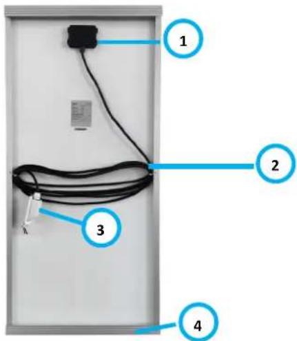
| MSMO-75 | MSMO-100 | MSMO-120 | MSMO-140 | MSMO-160 | MSMO-180 | MSMO-200 | |
| Maksimal effekt (Pmax) | 75W | 100W | 120W | 140W | 160W | 180W | 200W |
| Spenning ved Pmax (Vmpp) | 18.56 V | 23.2 V | 19.14 V | 22.62 V | 24.36 V | 24.36 V | 24.36 V |
| Strøm ved Pmax (Impp) | 4.04 A | 4.31 A | 6.27 A | 6.19 A | 6.57 A | 7.39 A | 8.21 A |
| Åpen kretsspenning (Voc) | 21.76 V | 27.2 V | 22.11 V | 26.13 V | 28.14 V | 28.14 V | 28.14 V |
| Kortslutningsstrøm (isc) | 4.28 A | 4.57 A | 6.65 A | 6.56 A | 6.96 A | 7.83 A | 8.70 A |
Serie- og parallellkobling
natural_image
Pure technical line drawing of a mechanical component without any text, numbers, or symbols- Serie- en parallelschakeling
- General instructions
- Assembly
- General assembly instructions:
- Determining location:
- Mounting:
- Routing cables:
- Series and parallel connection
- Parallel:
- Maintenance
- Recycling
- Declaration of conformity
- DEUTSCH
- Allgemeine Hinweise
- Istruzioni generali
- Generelle instruktioner
- Serie- og parallellkobling
Brand : Mestic
Model : MSMO-75
Category : Solar panel