
DE7461 - Table saw accessory DEWALT - Free user manual and instructions
Find the device manual for free DE7461 DEWALT in PDF.

User questions about DE7461 DEWALT
0 question about this device. Answer the ones you know or ask your own.
Ask a new question about this device
Download the instructions for your Table saw accessory in PDF format for free! Find your manual DE7461 - DEWALT and take your electronic device back in hand. On this page are published all the documents necessary for the use of your device. DE7461 by DEWALT.
USER MANUAL DE7461 DEWALT
A
B
 |  |
| C1 | C2 |
 |  |
| [C3] | |
 |  |
| [D1 D2] | |
 |  |
| E1 |
J1
J2
K
natural_image
Technical diagram of a mechanical assembly with labeled parts 43 and 44 (no text or symbols beyond labels)L1
L2
L3
M
N
LILLE GLIDEBORD DE7461
Tillykke!
1 Torx-Schlüssel T50
You have chosen a DeWALT product. Years of experience, thorough product development and innovation make DeWALT one of the most reliable partners for professional users.
Table of contents
| Technical data en - 1 |
| Manufacturer's declaration en - 1 |
| Safety instructions en - 1 |
| Package contents en - 1 |
| Description en - 2 |
| Assembly and adjustment en - 2 |
| Maintenance en - 4 |
| Guarantee en - 4 |
Technical data
DE7461
| Length mm 420 |
| Width mm 686 |
| Height mm 100 |
| Weight kg 53.6 |
The following symbols are used throughout this manual:

Denotes risk of personal injury, loss of life or damage to the tool in case of non-observance of the instructions in this manual.
Manufacturer's declaration

DE7461
DEWALT declares that this unit has been designed in compliance with 98/37/EEC.
This unit must not be put into service until it was established that the Power Tool to be connected to this unit is in compliance with 98/37/EEC (identified by the CE-marking on the Power Tool).
Director Engineering and Product Development Horst Großmann

Observe the safety regulations in the instruction manual of the Power Tool to be connected to this attachment. Also observe any applicable additional safety rules. Read the following safety instructions before attempting to operate this product. Keep these instructions in a safe place!
General
1 Keep work area clean
Cluttered areas and benches can cause accidents.
2 Keep children away
Do not let children come into contact with the tool or its attachments. Keep all people away from the work area.
3 Dress properly
Do not wear loose clothing or jewellery. They can be caught in moving parts. Preferably wear rubber gloves and non-slip footwear when working outdoors. Wear protective hair covering to keep long hair out of the way.
4 Wear safety goggles
Also use a face or dust mask in case the operations produce dust or flying particles.
5 Beware of maximum sound pressure
Take appropriate measures for the protection of hearing if the sound pressure of 85 dB(A) is exceeded.
6 Stay alert
Watch what you are doing. Use common sense. Do not operate the tool when you are tired.
7 Use appropriate tool
The intended use is laid down in this instruction manual. Do not force small tools or attachments to do the job of a heavy-duty tool. The tool will do the job better and safer at the rate for which it was intended.
Warning! The use of any accessory or attachment or performance of any operation with this tool, other than those recommended in this instruction manual may present a risk of personal injury.
8 Have your Power Tool Attachment repaired by an authorized DEWALT repair agent
Repair of your Power Tool Attachment being a matter of precision and skill, always take it to your DeWALT Authorized Repair Agent.
Package contents
The package contains:
1 Box containing:
1 Sliding table
1 Support bracket
2 Support rails
3 Rear support brackets
2 Stabilizing legs
1 Mitre gauge
1 Mitre gauge stop
1 Mitre gauge clamp
1 Box containing:
1 Torx wrench T50
11 Hex head bolts M10 x 35
4 Hex head bolts M8 x 55
2 Coach bolts M8 x 25
3 Torx bolts T50, M10 x 30
11 Hex nuts M10
10 Hex nuts M8
10 Lock washers 8 mm
11 Lock washers 10 mm
2 Flat washers 8 mm
7 Flat washers 10 mm
8 Large flat washers 10 mm
4 Leg clamp brackets
2 Cap head screws 5 x 16 mm
1 Instruction manual
1 Exploded drawing
- Check for damage to the tool, parts or accessories which may have occurred during transport.
- Take the time to thoroughly read and understand this manual prior to operation.
Description (fig. A1 & A2)
Your DE7461 small sliding table has been designed to extend the capabilities of your DEWALT woodworker's table saw.
Fig. A
1 Sliding table
2 Rear rail
3 Front rail
4 Leg stabilizer
Assembly and adjustment

Also refer to the manual of the machine to be used with this attachment.
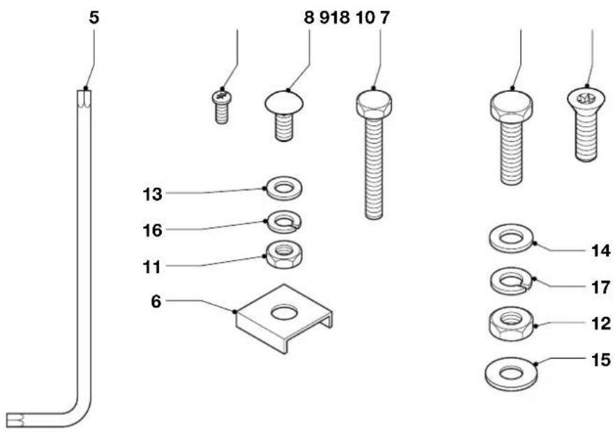
Identifying the hardware parts (fig. B)
We recommend that you unpack and sort all hardware parts.
5 Torx wrench T50
6 Leg clamp bracket
7 Torx bolt T50, M10 x 30
8 Coach bolt M8 x 25
9 Hex head bolt M8 x 55
10 Hex head bolt M10 x 35
11 Hex nut M8
12 Hex nut M10
13 Flat washer M8
14 Flat washer M10
15 Large flat washer M10
16 Lock washer M8
17 Lock washer M10
18 Cap head screw 5 x 16 mm
Required and recommended tools
Apart from the tools included with the attachment, the following tools are required:
- Flat blade screwdriver
- Open end wrench 16 mm
- Open end wrench 13 mm
- Ruler
- Soft hammer (or regular hammer and block of wood)
The following tools would be helpful:
- Socket wrench 16 mm
- Socket wrench 13 mm

Always use the correct type and size of tool.
Preparations before assembling and mounting the attachment
In case the machine has already been set up, you will need to remove the accessories and some of the parts including the associated hardware.
- Remove all accessories attached to the saw.
- Remove the support table attached to the left-hand side of the saw.
- If attached, remove the outfeed table.
- Remove the ripping fence, front rail and rear rail.
In case the machine has not been set up yet, you will need to mount some of the parts in advance.
- Unpack the saw.
- Mount the bevel adjuster.
- Mount the wrench hook.

Refer to the manual of the machine to perform these preparations.
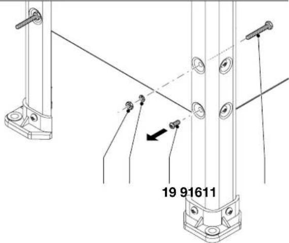
Replacing the leg screws (fig. C1 & C2)
Required hardware parts: 4 hex head bolts (9), 4 lock washers (16), 4 nuts (11) (fig. C1).
In order to mount the leg stabilizers, you need to replace the leg screws at the left-hand side of the machine.
- Replace the first screw (19) with the hex head bolt (9).
- Place a lock washer (16) and a nut (11) onto the end of the bolt.
- Tighten the nut.
- Repeat the procedure for the other screws.
- Continue one at a time, until all four bolts have been fixed.

Replace the screws one at a time. Don't replace the screws simultaneously!
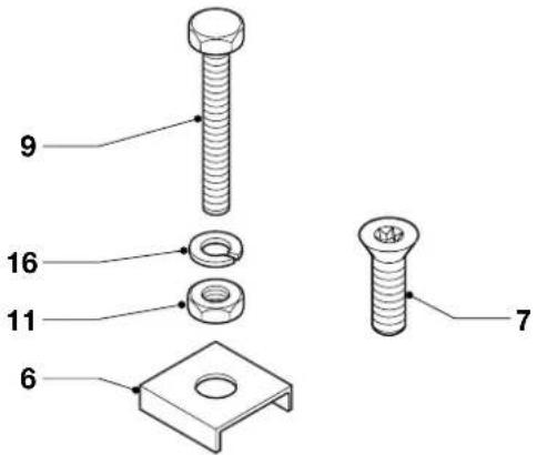
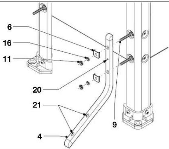
Mounting the leg stabilizers (fig. C1 & C3)
The leg stabilizers can be mounted for conventional use or for use with the DE7460 mobile base.
Conventional mounting
Required hardware parts: 4 leg clamp brackets (6), 4 lock washers (16), 4 nuts (11) (fig. C1).
- Place the leg stabilizer (4) over the bolts (9) using the slots that have been marked by the identification mark (20) (fig. C3).
- Place a leg clamp bracket (6), a lock washer (16) and a nut (11) onto the end of each of the bolts.
- Tighten the nuts finger tight.
- Repeat the procedure for the other leg stabilizer.
Mounting for use with DE7460 mobile base
Required hardware parts: 4 leg clamp brackets (6), 4 lock washers (16), 4 nuts (11) (fig. C1).
- Place the leg stabilizer (4) over the bolts (9) using the unmarked slots (21) (fig. C3).
- Place a leg clamp bracket (6), a lock washer (16) and a nut (11) onto the end of each of the bolts.
- Tighten the nuts finger tight.
- Repeat the procedure for the other leg stabilizer.
Adjusting the leg stabilizers (fig. C3)
- Make sure that the leg stabilizers (4) contact the floor.
- Securely tighten the nuts (11).
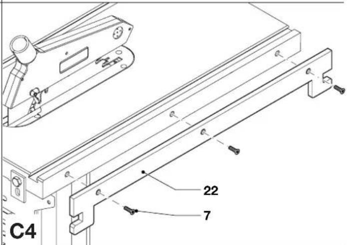
Mounting the support bracket (fig. C1 & C4)
Required hardware parts: 3 Torx bolts (11) (fig. C1).
- Hold the support bracket (22) against the left-hand side of the machine (fig. C4).
- Mount the support bracket to the machine using the Torx bolts (7).
Assembling the front rail (fig. D1 & G2)
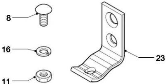
Required hardware parts: 5 coach bolts (8), 3 front rail brackets (23), 3 lock washers (16), 3 nuts (11) (fig. D1).
- Insert a coach bolt (8) into the bottom hole of each of the front rail brackets (23) (fig. D2).
-
Place a lock washer (16) and nut (11) onto the coach bolts and tighten the nuts a few threads.
-
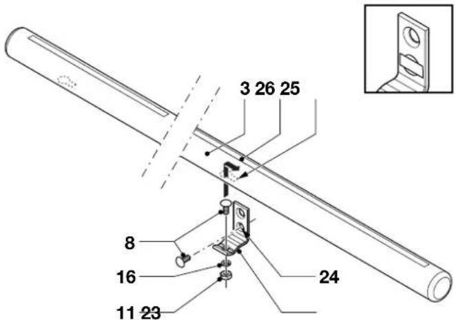
Insert a coach bolt into the lower hole (24) of two of the brackets. Keep the bolts in place with a piece of tape.
- Insert the head of the coach bolts into the keyhole slots (25) in the front rail (3) leaving the outer left position empty. Make sure that the brackets are pointing up (with the scale (26) on the front rail facing up).
- Engage the square part of the bolts.
- Tighten the nuts finger tight.
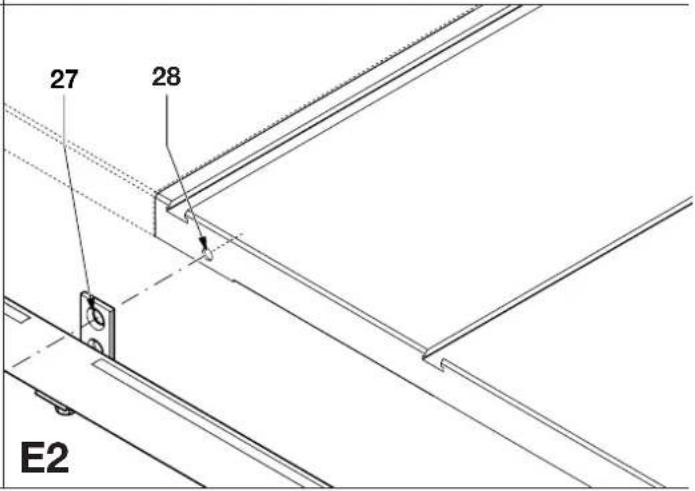
Mounting the front rail to the saw (fig. E1 - E3)
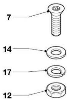
Required hardware parts: 3 Torx bolts (7), 3 flat washers (14), 3 lock washers (17), 3 nuts (12) (fig. E1).
- Make sure that a support table is mounted to the right-hand side of the machine.
- Hold the front rail (3) against the front side of table top with the brackets (23) pointing up (fig. E3).
- Align the upper holes (27) in the brackets with the corresponding holes (28) in the table top (fig. E2).
- Insert a Torx bolt (7) into the upper holes in the brackets and the table top (fig. E3).
- Place a flat washer (14), a lock washer (17) and a nut (12) onto the end of each of the Torx bolts.
- Tighten the nuts finger tight.
- Tighten the rail bracket nuts holding the front rail to the machine.
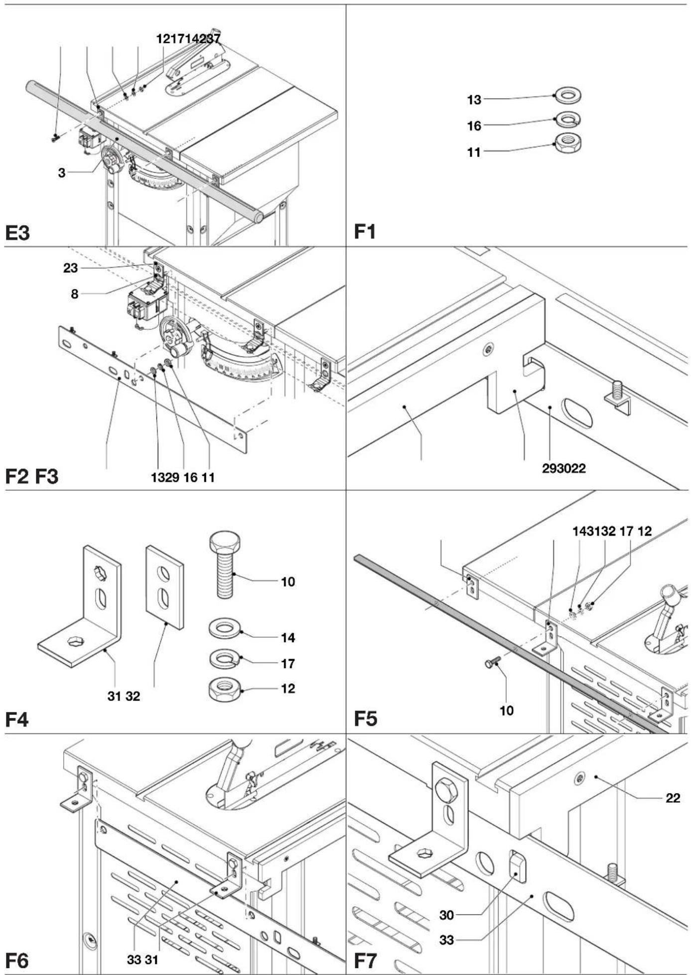
Mounting the front support rail (fig. F1 - F3)
Required hardware parts: 2 flat washers (13), 2 lock washers (16), 2 nuts (11) (fig. F1).
- Hold the front support rail (29) against the back side of the brackets (23) with the coach bolts (8) into the holes as shown (fig. F2).
- The tab (30) on the support bracket (22) should fit in the rectangular hole of the support rail (29) as shown (fig. F3).
- Place a flat washer (13), a lock washer (16) and a nut (11) onto the end of each of the coach bolts (fig. F2).
- Tighten the nuts.
Mounting the rear support rail (fig F4 - F7)
Required hardware parts: 2 L-shaped brackets (31), 1 flat bracket (32), 3 hex head bolts (10), 3 flat washers (14), 3 lock washers (17), 3 nuts (12) (fig. F4).
The rear support rail should be mounted in conjunction with the rear rail.
- Mount 2 L-shaped brackets (31) for the outfeed table to the rear of the machine using hex head bolts (10), flat washers (14), lock washers (17) and nuts (12) as shown (fig. F5). Make sure that the brackets are at a right angle to the saw table.
- Mount 1 flat bracket (32) to the rear of the support table using a hex head bolt (10), a flat washer (14), a lock washer (17) and a nut (12).
- Hold the rear support rail (33) against the back side of the brackets (31) as shown (fig. F6).
- The tab (30) on the support bracket (22) should fit in the rectangular hole of the support rail (33) as shown (fig. F7).
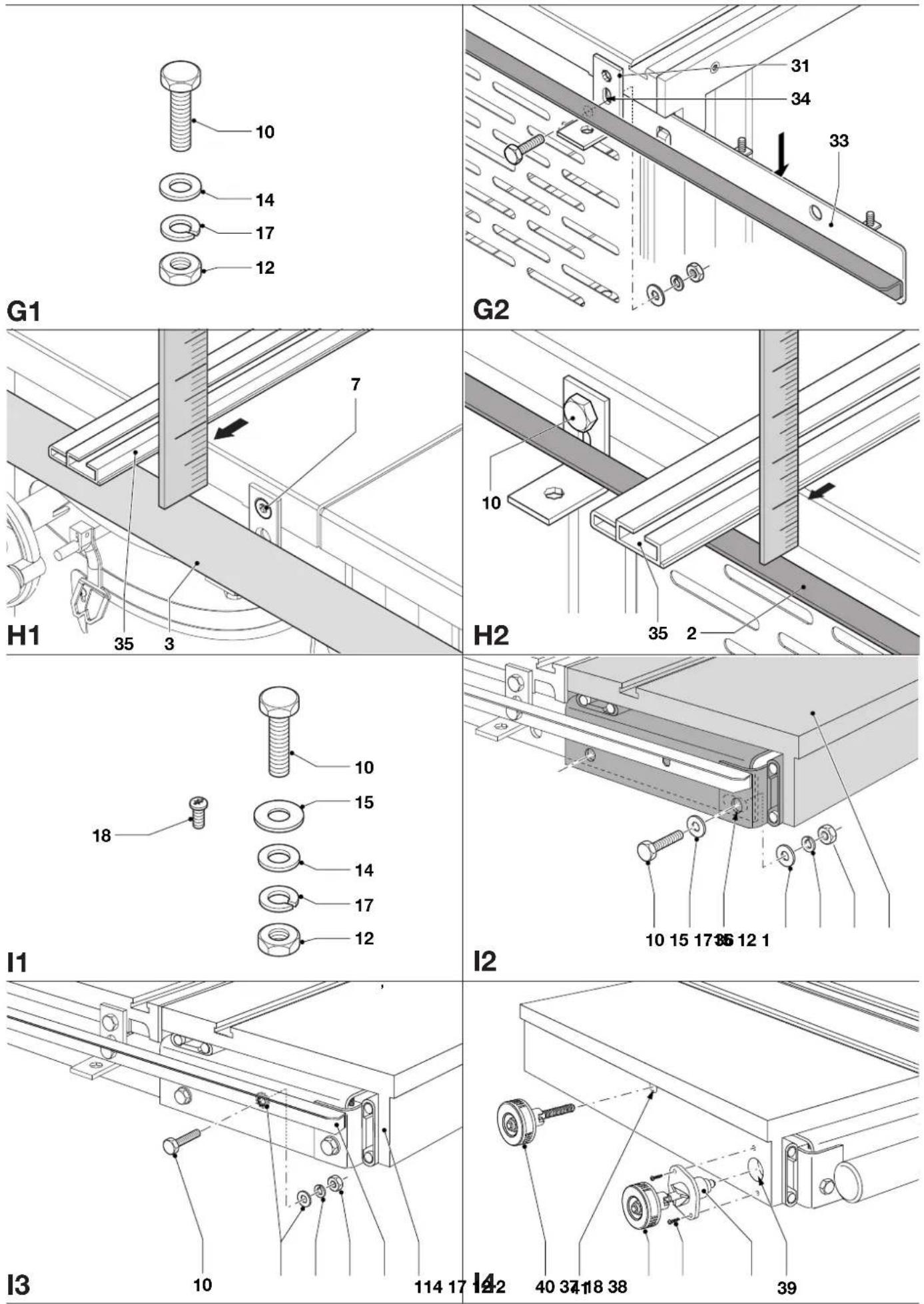
Mounting the rear rail to the saw (fig. G1 & G2)
Required hardware parts: 3 hex head bolts (10), 3 flat washers (14), 3 lock washers (17), 3 nuts (12) (fig. G1).
- With the rear support rail (33) held in its position, leaving the outer left hole empty (from the woodworker's point of view), align 2 holes in the rear rail (2) with the lower holes (34) in the L-shaped brackets (31). The flat side of the rail should be facing up (fig. G2).
- Mount the rear rail and the rear support rail to the brackets using short hex head bolts (10), flat washers (14), lock washers (17) and nuts (12). Do not fully tighten.
Parallel the rails to the table top
Front rail (fig. H1)
- Use the fence face (35) to extend the table surface over the front rail (3).
- Using a ruler, measure the distance between the table top and the rail at both ends of the table top. The distance should be equal at both ends.
- If adjustment is required, slacken the bolts (10) holding the brackets to the saw. Tap the brackets using a soft hammer until the distances are equal at both ends of the table top.
- Securely tighten the bolts.
Rear rail (fig. H2)
- Use the fence face (35) to extend the table surface over the rear rail (2).
- Measure the distance between the table top and the rail at both ends of the table top. The distance should be equal at both ends.
- If adjustment is required, slacken the bolts (10) holding the brackets to the saw. Tap the brackets using a soft hammer until the distances are equal at both ends of the table top.
- Securely tighten the bolts.
Mounting the sliding table (fig. 11 - 13)
Required hardware parts: 5 hex head bolts (10), 8 large flat washers (15), 2 flat washer (14), 5 lock washers (17), 5 nuts (12) (fig. 11).
- Place the sliding table over the support rails and push up tight against the machine.
- Insert a bolt (10) with a large flat washer (15) placed onto it into each of the holes (36 in the front and rear side of the sliding table (1) and the support rails (fig. 12).
- Place a large flat washer (15), a lock washer (17) and a nut (12) onto the end of each of the bolts.
- Tighten the nuts finger tight.
- Hold a flat washer (14) in place between the rear rail (2) and the side of the sliding table (1) (fig. 13).
- Insert a hex head bolt (10) into the holes in the rear rail and the sliding table.
- Place a flat washer (14), a lock washer (17) and a nut (12) onto the end of the bolt.
- Tighten the nut finger tight.

The sliding table has been equipped with shipping plugs to limit slide movement. Do not remove the shipping plugs before the sliding table has been fully installed!
Mounting the slide locking knob (fig. 11 & 14)
Required hardware parts: 2 cap head screws (18) (fig. I1).
- Set the slide locking knob (37) to the unlock position with the pin (38) most retracted (fig. 14).
- Place the knob with the pin fitting into the hole (39).
- Mount the knob to the table using the screws (18).
- Set the knob to the lock position. The lock will automatically engage.
Mounting the mitre locking knob (fig. 14)
- Screw the mitre locking knob (40) into the hole (41).
- Tighten the locking knob hand tight.
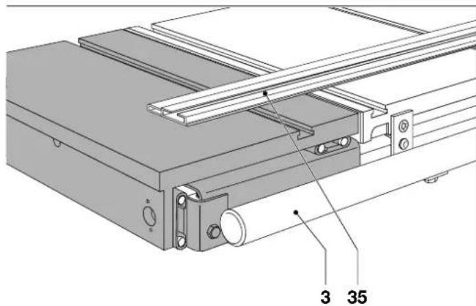
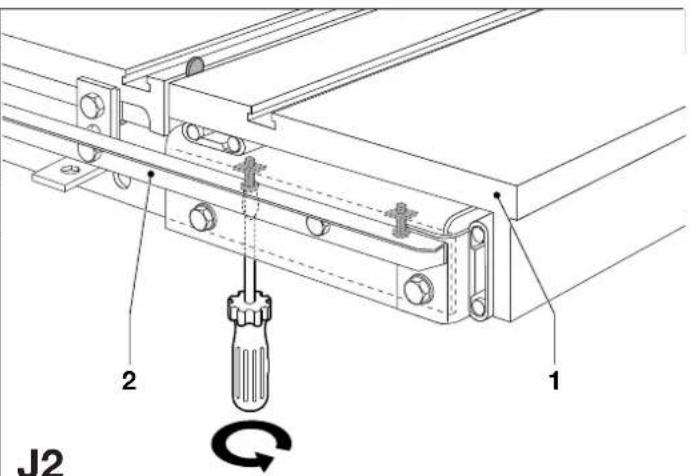
Parallel the sliding table to the table top (fig. I2, I3, J1 & J2)
The table height should be just above flush with the table saw top.
- Use the fence face (35) to extend the table surface over the sliding table (fig. J1).
- Use the leveling hardware (fig. J2) to adjust, gauging against the rear rail (2) and front rail (3) (fig. J1).
- Slightly move the sliding table (1) from the table saw top creating a small clearance (fig. J2).
- Use a thin object, e.g. a small coin, to gauge the gap along its length. Adjust the sliding table to make the gap consistent.
- Securely tighten the fasteners holding the sliding table to the machine (fig. 12 & 13).
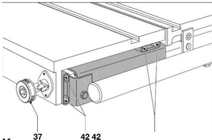
Removing the shipping plugs (fig. K)
- Set the slide locking knob (37) to the unlock position.
- Use a soft hammer to tap the rear of the sliding table enforcing the shipping plugs (42) to come off.
- Once the plugs have been removed the sliding table should move freely.

Save the shipping plugs for future transportation.
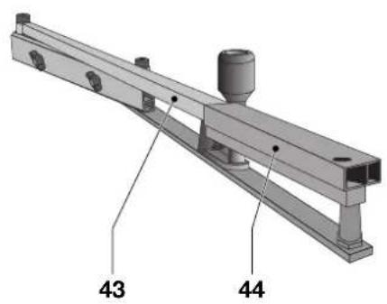
Assembling the mitre gauge (fig. L1 - L3)
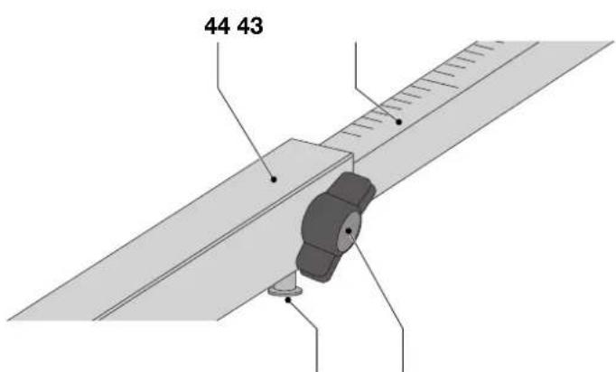
- Insert the scale (43) into the telescope arm (44) (fig. L1).
- Set the telescope arm (44) to 90^ using the scale (43) (fig. L2).
- Tighten the locking knob (45).
- Slide the assembly into the slot in the sliding table (fig. L3).
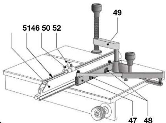
- Slide the mitre fence (46) onto the fence base (47).
- Tighten the locking knobs (48).
- Place the quick release clamp (49) on the assembly with the clamp fully turned up and facing rearward.
- Slide the adjustable stop (50) into the slot (51) on top of the mitre fence.
• Tighten the locking knob (52).
Adjusting the mitre angle (fig. L2)
- Loosen the locking knob (45).
- Set the telescope arm (44) to the required angle using the scale (43).
- Tighten the locking knob.
Angle detent system (fig. L2)
The detent system can be used for easily setting of frequently used mitre angles.
- Loosen the locking knob (45).
- Set the telescope arm (44) to the required angle using the scale (43).
- Press and hold the detent button (52) and slide the scale in until the detent catches.
- Tighten the locking knob.
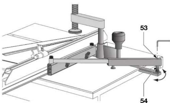
Mitre gauge calibration (fig. M)
- Set the mitre angle to 90^ .
- Loosen the Allen screw (53).
- Tum the eccentric (54) to create a perfect 90^ mitre angle using a square.
- Tighten the Allen screw.
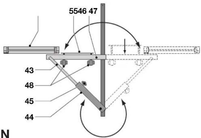
Reversing the mitre gauge (fig. N)
- Loosen the locking knobs (48) and remove the mitre fence (46).
- Remove the locking knobs (48) and the clamping plate (55) from the fence base (47).
- Loosen the locking knob (45) and pull the scale (43) out of the telescope arm (44).
- Rotate the telescope arm and the fence base to the opposite side.
- Insert the scale into the telescope arm and tighten the locking knob (45).
- Mount the clamping plate and the locking knobs (48).
- Mount the fence and tighten the locking knobs (48).
Consult your dealer for further information on the appropriate accessories.
Maintenance
Your DeWALT attachment has been designed to operate over a long period of time with a minimum of maintenance. Continuous satisfactory operation depends upon proper tool care and regular cleaning.

Cleaning
- On a daily basis, remove sawdust from the sliding table and the sliding support.

Lubricating the slides
The sliding system should periodically be lubricated.
- Regularly clean and lubricate the ball-bearing slides in the sliding support.

Unwanted products and the environment
Take your attachment to an authorized DeWALT repair agent where it will be disposed of in an environmentally safe way.
GUARANTEE
• 30 DAY NO RISK SATISFACTION GUARANTEE •
If you are not completely satisfied with the performance of your DEWALT tool, simply return it within 30 days, complete as purchased, to the point of purchase, for a full refund or exchange. Proof of purchase must be produced.
• ONE YEAR FREE SERVICE CONTRACT •
If you need maintenance or service for your DEWALT tool, in the 12 months following purchase, it will be undertaken free of charge at an authorized DEWALT repair agent. Proof of purchase must be produced. Includes labour and spare parts for the attachments. Excludes accessories.
• ONE YEAR FULL WARRANTY •
If your D≡WALT product becomes defective due to faulty materials or workmanship within 12 months from the date of purchase, we guarantee to replace all defective parts free of charge or, at our discretion, replace the unit free of charge provided that:
• The product has not been misused.
• Repairs have not been attempted by unauthorized persons.
• Proof of purchase date is produced.
This guarantee is offered as an extra benefit and is additional to consumers statutory rights.
For the location of your nearest authorized DEWALT repair agent, please use the appropriate telephone number on the back of this manual. Alternatively, a list of authorized DEWALT repair agents and full details on our after-sales service are available on the Internet at www.2helpU.com.
MESA PEQUEÑA DE DESLIZAMIENTO DE7461
¡Enhorabuena!
Director Engineering and Product Development
Horst Großmann

L'emballage contient:
1 Boîte contenant:
1 Table coulissante
1 Étrier de support
2 Barres d'appui
Director Engineering and Product Development
Horst Großmann

Director Engineering and Product Development Horst Großmann

DeWALT, Richard-Klinger-Straße 40, D-65510, Idstein, Tyskland
Sikkerhetsforskrifter
Director Engineering and Product Development Horst Großmann

DeWALT, Richard-Klinger-Straße 40, D-65510, Idstein, Alemanha
Director Engineering and Product Development
Horst Großmann

Your DE7461 small sliding table has been designed to extend the capabilities of your DEWALT woodworker's table saw.
Director Engineering and Product Development Horst Großmann

DeWALT, Richard-Klinger-Straße 40, D-65510, Idstein, Tyskland
Säkerhetsinstruktioner
3 Vridbult T50, M10 x 30
11 Sexkantmutter M10
10 Sexkantmutter M8
10 Spärrbricka 8 mm