
GCM 340-305 D Professional - Saw BOSCH - Free user manual and instructions
Find the device manual for free GCM 340-305 D Professional BOSCH in PDF.

| Product Type | Radial miter saw (miter saw combined with radial movement) |
| Brand | Bosch |
| Model | GCM 340-305 D Professional |
| Category | Saw |
| Weight | 22.2 kg (without cord and plug) |
| Rated power input | 1800 W |
| Rated voltage | 230 V ~ |
| No-load speed | 4050 rpm |
| Blade diameter | 305 mm |
| Arbor hole | 25.4 mm |
| Blade body thickness | 1.4 – 2.2 mm |
| Max. cut width | 3.2 mm |
| Miter angle range (horizontal) | -52° to +60° |
| Bevel angle range (vertical) | 47° left to 47° right |
| Max. cutting capacity (0°/0°) | 105 x 340 mm (height x width) |
| Max. cutting depth | 105 mm |
| Main functions | Radial motion, pulling device, quick adjustment of standard angles, LED lighting, groove cutting, integrated dust extraction |
| Maintenance and cleaning | Clean the ventilation slots, sliding carriage, and protective cover regularly; replace the blade when worn; empty the dust bag |
| Safety | Pendulum protective cover, transport safety, spindle lock, switch lock, quick stop |
| Spare parts and repairability | Included accessories: dust bag, dust extraction adapter, 2 workpiece supports, clamp, hex key, protractor triangle. Repair by authorized Bosch service centers. |
| General information | Intended for stationary sawing of wood, aluminum, and plastics. Use blades conforming to EN 847-1. |
Frequently Asked Questions - GCM 340-305 D Professional BOSCH
User questions about GCM 340-305 D Professional BOSCH
0 question about this device. Answer the ones you know or ask your own.
Ask a new question about this device
Download the instructions for your Saw in PDF format for free! Find your manual GCM 340-305 D Professional - BOSCH and take your electronic device back in hand. On this page are published all the documents necessary for the use of your device. GCM 340-305 D Professional by BOSCH.
USER MANUAL GCM 340-305 D Professional BOSCH
natural_image
Mechanical assembly of a cutting mill with a blade and workpiece (no visible text or symbols)en Original instructions
fr Notice originale
pt Manual original
zh 正本使用说明书
zh原始使用說明書
English ...... Page 14
Français Page 23
natural_image
Mechanical assembly diagram showing a cutting machine with a workpiece, mounted on a workbench (no text or symbols visible)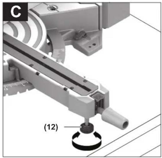
natural_image
Mechanical assembly diagram showing a robotic arm with a labeled component (12), no readable text or symbols present.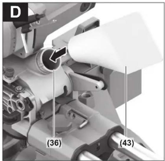
Bosch Power Tools 1 609 92A C5U | (09.04.2025)
8
1 609 92A C5U | (09.04.2025) Bosch Power Tools
|9
natural_image
Mechanical assembly diagram showing internal components and a numbered label (28), with an arrow indicating direction (no readable text or symbols beyond label)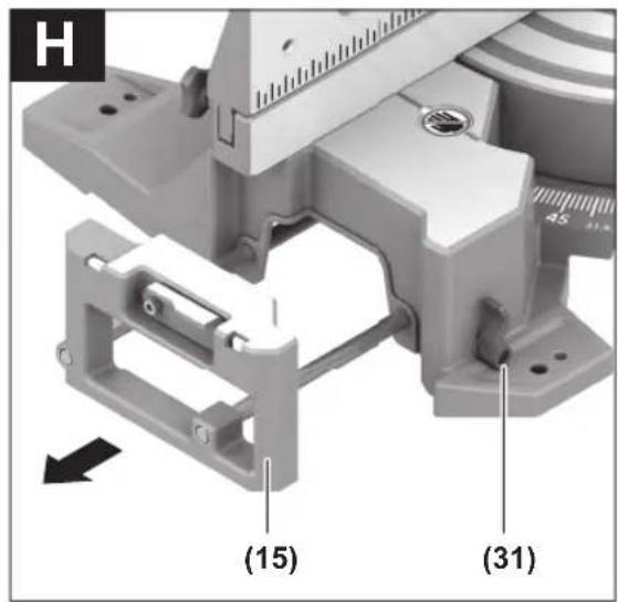
natural_image
Group of identical 3D-rendered mechanical devices arranged in two rows, each with a small box on its side (no text or symbols visible)10
natural_image
Mechanical assembly diagram showing internal components and motion arrows (no text or symbols)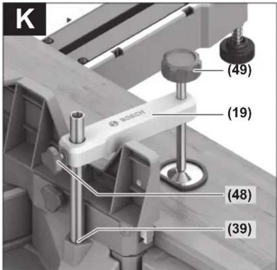
1 609 92A C5U | (09.04.2025) Bosch Power Tools
|11
natural_image
Close-up of a mechanical device with labeled component (53), no readable text or symbols beyond label and numbers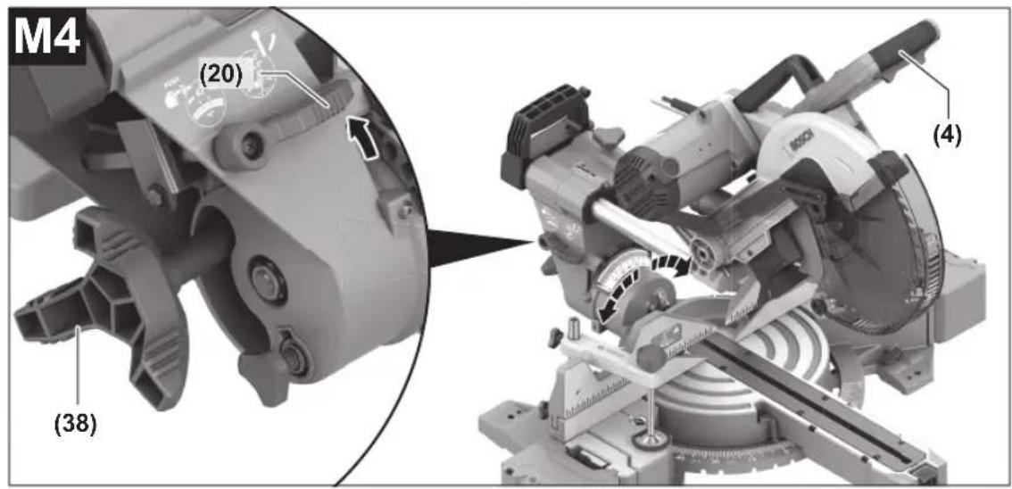
natural_image
Person using a Bosch cutting cutter on a workbench (no text or symbols visible)Bosch Power Tools 1 609 92A C5U | (09.04.2025)
12
natural_image
Close-up of a cut-out mechanical machine with visible blade and cutting edge (no text or symbols)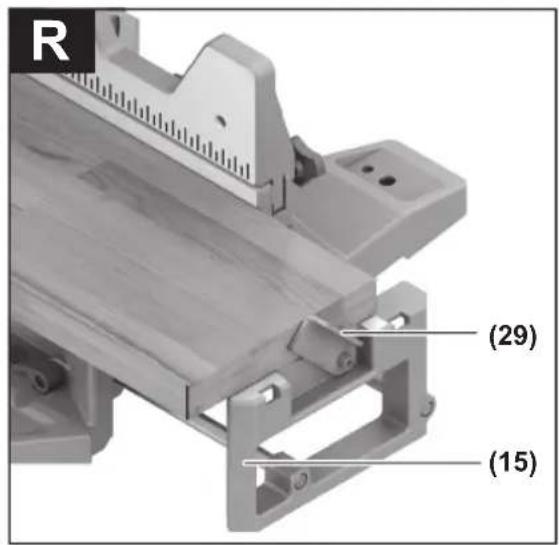
| 13

natural_image
Mechanical assembly diagram showing internal components and labeled parts (U2, 56), no readable text or symbols beyond labels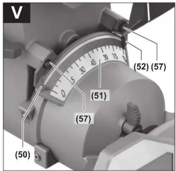
English
Safety instructions
General Power Tool Safety Warnings
WARNING
Read all safety warnings, instructions, illustrations and specifica-
tions provided with this power tool. Failure to follow all instructions listed below may result in electric shock, fire and/or serious injury.
Save all warnings and instructions for future reference.
The term "power tool" in the warnings refers to your mains-operated (corded) power tool or battery-operated (cordless) power tool.
Work area safety
▶ Keep work area clean and well lit. Cluttered or dark areas invite accidents.
▶ Do not operate power tools in explosive atmospheres, such as in the presence of flammable liquids, gases or dust. Power tools create sparks which may ignite the dust or fumes.
▶ Keep children and bystanders away while operating a power tool. Distractions can cause you to lose control.
Electrical safety
▶ Power tool plugs must match the outlet. Never modify the plug in any way. Do not use any adapter plugs with earthed (grounded) power tools. Unmodified plugs and matching outlets will reduce risk of electric shock.
▶ Avoid body contact with earthed or grounded surfaces, such as pipes, radiators, ranges and refrigerators. There is an increased risk of electric shock if your body is earthed or grounded.
▶ Do not expose power tools to rain or wet conditions. Water entering a power tool will increase the risk of electric shock.
▶ Do not abuse the cord. Never use the cord for carrying, pulling or unplugging the power tool. Keep cord away from heat, oil, sharp edges or moving parts.
Damaged or entangled cords increase the risk of electric shock.
▶ When operating a power tool outdoors, use an extension cord suitable for outdoor use. Use of a cord suitable for outdoor use reduces the risk of electric shock.
▶ If operating a power tool in a damp location is unavoidable, use a residual current device (RCD) protected supply. Use of an RCD reduces the risk of electric shock.
Personal safety
▶ Stay alert, watch what you are doing and use common sense when operating a power tool. Do not use a power tool while you are tired or under the influence of drugs, alcohol or medication. A moment of inatten-
tion while operating power tools may result in serious personal injury.
▶ Use personal protective equipment. Always wear eye protection. Protective equipment such as a dust mask, non-skid safety shoes, hard hat or hearing protection used for appropriate conditions will reduce personal injuries.
▶ Prevent unintentional starting. Ensure the switch is in the off-position before connecting to power source and/or battery pack, picking up or carrying the tool. Carrying power tools with your finger on the switch or energising power tools that have the switch on invites accidents.
Remove any adjusting key or wrench before turning the power tool on. A wrench or a key left attached to a rotating part of the power tool may result in personal injury.
▶ Do not overreach. Keep proper footing and balance at all times. This enables better control of the power tool in unexpected situations.
▶ Dress properly. Do not wear loose clothing or jewellery. Keep your hair and clothing away from moving parts. Loose clothes, jewellery or long hair can be caught in moving parts.
▶ If devices are provided for the connection of dust extraction and collection facilities, ensure these are connected and properly used. Use of dust collection can reduce dust-related hazards.
Do not let familiarity gained from frequent use of tools allow you to become complacent and ignore tool safety principles. A careless action can cause severe injury within a fraction of a second.
Power tool use and care
▶ Do not force the power tool. Use the correct power tool for your application. The correct power tool will do the job better and safer at the rate for which it was designed.
▶ Do not use the power tool if the switch does not turn it on and off. Any power tool that cannot be controlled with the switch is dangerous and must be repaired.
▶ Disconnect the plug from the power source and/or remove the battery pack, if detachable, from the power tool before making any adjustments, changing accessories, or storing power tools. Such preventive safety measures reduce the risk of starting the power tool accidentally.
▶ Store idle power tools out of the reach of children and do not allow persons unfamiliar with the power tool or these instructions to operate the power tool. Power tools are dangerous in the hands of untrained users.
- Maintain power tools and accessories. Check for misalignment or binding of moving parts, breakage of parts and any other condition that may affect the power tool's operation. If damaged, have the power tool repaired before use. Many accidents are caused by poorly maintained power tools.
▶ Keep cutting tools sharp and clean. Properly maintained cutting tools with sharp cutting edges are less likely to bind and are easier to control.
▶ Use the power tool, accessories and tool bits etc. in accordance with these instructions, taking into account the working conditions and the work to be performed. Use of the power tool for operations different from those intended could result in a hazardous situation.
▶ Keep handles and grasping surfaces dry, clean and free from oil and grease. Slippery handles and grasping surfaces do not allow for safe handling and control of the tool in unexpected situations.
Service
▶ Have your power tool serviced by a qualified repair person using only identical replacement parts. This will ensure that the safety of the power tool is maintained.
Safety Warnings for Mitre Saws
- Mitre saws are intended to cut wood or wood-like products, they cannot be used with abrasive cut-off wheels for cutting ferrous material such as bars, rods, studs, etc. Abrasive dust causes moving parts such as the lower guard to jam. Sparks from abrasive cutting will burn the lower guard, the kerf insert and other plastic parts.
▶ Use clamps to support the workpiece whenever possible. If supporting the workpiece by hand, you must always keep your hand at least 100 mm from either side of the saw blade. Do not use this saw to cut pieces that are too small to be securely clamped or held by hand. If your hand is placed too close to the saw blade, there is an increased risk of injury from blade contact.
The workpiece must be stationary and clamped or held against both the fence and the table. Do not feed the workpiece into the blade or cut "freehand" in any way. Unrestrained or moving workpieces could be thrown at high speeds, causing injury.
▶ Push the saw through the workpiece. Do not pull the saw through the workpiece. To make a cut, raise the saw head and pull it out over the workpiece without cutting, start the motor, press the saw head down and push the saw through the workpiece. Cutting on the pull stroke is likely to cause the saw blade to climb on top of the workpiece and violently throw the blade assembly towards the operator.
▶ Never cross your hand over the intended line of cutting either in front or behind the saw blade. Supporting the workpiece “cross handed” i.e. holding the workpiece to the right of the saw blade with your left hand or vice versa is very dangerous.
▶ Do not reach behind the fence with either hand closer than 100 mm from either side of the saw blade, to remove wood scraps, or for any other reason while the blade is spinning. The proximity of the spinning saw blade to your hand may not be obvious and you may be seriously injured.
Inspect your workpiece before cutting. If the workpiece is bowed or warped, clamp it with the outside bowed face toward the fence. Always make certain that there is no gap between the workpiece, fence and table along the line of the cut. Bent or warped workpieces can twist or shift and may cause binding on the spinning saw blade while cutting. There should be no nails or foreign objects in the workpiece.
Do not use the saw until the table is clear of all tools, wood scraps, etc., except for the workpiece. Small debris or loose pieces of wood or other objects that contact the revolving blade can be thrown with high speed.
▶ Cut only one workpiece at a time. Stacked multiple workpieces cannot be adequately clamped or braced and may bind on the blade or shift during cutting.
▶ Ensure the mitre saw is mounted or placed on a level, firm work surface before use. A level and firm work surface reduces the risk of the mitre saw becoming unstable.
Plan your work. Every time you change the bevel or mitre angle setting, make sure the adjustable fence is set correctly to support the workpiece and will not interfere with the blade or the guarding system. Without turning the tool "ON" and with no workpiece on the table, move the saw blade through a complete simulated cut to assure there will be no interference or danger of cutting the fence.
▶ Provide adequate support such as table extensions, saw horses, etc. for a workpiece that is wider or longer than the table top. Workpieces longer or wider than the mitre saw table can tip if not securely supported. If the cut-off piece or workpiece tips, it can lift the lower guard or be thrown by the spinning blade.
▶ Do not use another person as a substitute for a table extension or as additional support. Unstable support for the workpiece can cause the blade to bind or the workpiece to shift during the cutting operation pulling you and the helper into the spinning blade.
The cut-off piece must not be jammed or pressed by any means against the spinning saw blade. If confined, i.e. using length stops, the cut-off piece could get wedged against the blade and thrown violently.
▶ Always use a clamp or a fixture designed to properly support round material such as rods or tubing. Rods have a tendency to roll while being cut, causing the blade to "bite" and pull the work with your hand into the blade.
▶ Let the blade reach full speed before contacting the workpiece. This will reduce the risk of the workpiece being thrown.
If the workpiece or blade becomes jammed, turn the mitre saw off. Wait for all moving parts to stop and disconnect the plug from the power source and/or remove the battery pack. Then work to free the jammed material. Continued sawing with a jammed workpiece could cause loss of control or damage to the mitre saw.
▶ After finishing the cut, release the switch, hold the saw head down and wait for the blade to stop before
16 | English
removing the cut-off piece. Reaching with your hand near the coasting blade is dangerous.
▶ Hold the handle firmly when making an incomplete cut or when releasing the switch before the saw head is completely in the down position. The braking action of the saw may cause the saw head to be suddenly pulled downward, causing a risk of injury.
▶ Do not let go of the handle once the saw head has reached the lowest position. Always guide the saw head back to the top position by hand. There is a risk of injury if the saw head moves in an uncontrolled manner.
- Keep your work area clean. Material mixtures are particularly hazardous. Light metal dust may catch fire or explode.
▶ Do not use dull, cracked, bent or damaged saw blades. Unsharpened or improperly set saw blades produce narrow kerf causing excessive friction, blade binding and kickback.
▶ Do not use saw blades made from high speed steel (HSS). Such saw blades can easily break.
▶ Always use saw blades with correct size and shape (diamond versus round) of arbour holes. Saw blades that do not match the mounting hardware of the saw will run off-centre, causing loss of control.
▶ Never remove cuttings, wood chips, etc. from the cutting area while the power tool is running. Always guide the tool arm back to the neutral position first and then switch the power tool off.
▶ Do not touch the saw blade after working before it has cooled. The saw blade becomes very hot while working.
Symbols
The following symbols may be important for the operation of your power tool. Please take note of these symbols and their meaning. Correctly interpreting the symbols will help you to operate the power tool more effectively and safely.
Symbols and their meaning

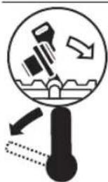
Keep hands away from the cutting area while the power tool is running. Contact with the saw blade can lead to injuries.

Wear a dust mask.

Wear safety goggles.
Symbols and their meaning

Wear hearing protection. Exposure to noise can cause hearing loss.

Danger area! Keep hands, fingers and arms away from this area.
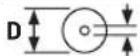
d Take note of the dimensions of the saw blade (saw blade diameter D, hole diameter d). The hole diameter d must match the tool spindle without play. If it is necessary to use reducers, ensure that the dimensions of the reducer are suitable for the base blade thickness and the saw blade hole diameter, as well as the tool spindle diameter. Wherever possible, use the reducers provided with the saw blade.
The saw blade diameter D must match the information specified on the symbol.
See also: "Dimensions of suitable saw blades" in the "Technical Data" section.
When sawing bevel angles, the adjustable fences must be pulled outwards or removed completely.
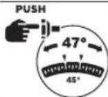
In order to adjust the right-hand bevel angle range, you must first tilt the tool arm slightly to the left and then push the adjusting lever to the left.
In order to set the entire bevel angle range up to 47^ (to the left and to the right), the lock button must be pushed in.
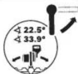
To adjust the standard bevel angle (22.5° and 33.9°), the locking lever must be released upwards.
Product Description and Specifications

Read all the safety and general instructions.
Failure to observe the safety and general instructions may result in electric shock, fire and/or serious injury.
Please observe the illustrations at the beginning of this operating manual.
Intended Use
The power tool is intended as a stationary machine for making straight cuts in wood with and against the grain. It is possible to cut mitre angles of -52^ to +60^ and bevel angles of 47^ (to the left) to 47^ (to the right).
The power tool is designed with sufficient capacity for sawing hardwood and softwood as well as chipboard and fibreboard.
When using appropriate saw blades, sawing aluminium profiles and plastic is also possible.
Product Features
The numbering of the product features refers to the diagram of the power tool on the graphics page.
(1) Locking screw for slide device
(2) Slide device
(3) Transport handle
(4) Handle
(5) Lock-off function for on/off switch
(6) Protective guard
(7) Retracting blade guard
(8) Mounting holes
(9) Insert plate
(10) Lock button for mitre angles
(11) Locking knob for all mitre angles
(12) Tilt protector
(13) Angle indicator for mitre angles
(14) Detents for standard mitre angles
(15) Saw table extension
(16) Workpiece support
(17) Fixed fence
(18) Adjustable fence
(19) Screw clamp
(20) Adjusting lever for the bevel angle range (to the left or right)
(21) Locking lever for standard bevel angle
(22) Guide roller
(23) Spindle lock
(24) Worklight outlet aperture
(25) Depth stop
(26) Depth stop adjusting screw
(27) Hex key
(28) Transport safety lock
(29) Length stop
(30) Recessed handles
(31) Clamping lever of the saw table extension
(32) Saw table
(33) Scale for mitre angles
(34) On/off switch
(35) On/Off switch for worklight
(36) Chip ejector
(37) Wing bolt for fixing the adjustable fence
(38) Clamping wheel for bevel angles
(39) Holes for screw clamp
(40) Opening for workpiece support (on power tool)
(41) Opening for second workpiece support (on workpiece support)
(42) Dust extraction adapter
(43) Dust bag
(44) Hex socket screw for mounting the saw blade
(45) Clamping flange
(46) Saw blade
(47) Inner clamping flange
(48) Wing bolt for adjusting the height of the threaded rod
(49) Threaded rod
(50) Angle indicator for right-hand bevel angle range
(51) Scale for bevel angle
(52) Angle indicator for left-hand bevel angle range
(53) Locking button for bevel angle 47°
(54) Screws for insert plate
(55) Set square
(56) Hex socket screw for fence
(57) Screws for bevel angle indicator
(58) Screw for mitre angle indicator
Technical Data
| Sliding Mitre Saw GCM 340-305 D | |
| Article number | 3 601 M60 0.. |
| Rated power input W 1800 | |
| No-load speed min | -1 4050 |
| Weight ^A) | kg 22.2 |
| Dimensions of suitable saw blades | |
| Saw blade diameter D | mm 305 |
| Base blade thickness mm 1.4–2.2 | |
| Max. cutting width mm 3.2 | |
18 | English
Sliding Mitre Saw GCM 340-305 D
Hole diameter d mm 25.4
A) Weight without mains connection cable and without mains plug The specifications apply to a rated voltage [U] of 230 V. These specifications may vary at different voltages and in country-specific models.
Values can vary depending on the product, scope of application and environmental conditions. To find out more, visit www.bosch-professional.com/wac.
Assembly
▶ Avoid starting the power tool unintentionally. The mains plug must not be connected to the power supply during assembly or when carrying out any kind of work on the power tool.
Items Included

See the list of items included at the start of the operating manual.
Check to ensure that all the parts listed below have been supplied before using the power tool for the first time:
- Sliding mitre saw with fitted saw blade
- Dust bag (43)
– Dust extraction adapter (42) - Workpiece support (16) (2 units)
- Screw clamp (19)
- Hex key (27)
- Set square (55)
Note: Check the power tool for possible damage.
Before continuing to use the power tool, carefully check that all protective devices or slightly damaged parts are working perfectly and according to specifications. Check that the moving parts are working perfectly and without jamming; check whether any parts are damaged. All parts must be fitted correctly and all the conditions necessary to ensure smooth operation must be met.
If the protective devices or any parts become damaged, you must have them properly repaired or replaced by an authorised service centre.
Fitting individual components
- Carefully remove all parts included in the delivery from their packaging.
- Remove all packing material from the power tool and the accessories provided.
Installing Workpiece Supports (see figure A)
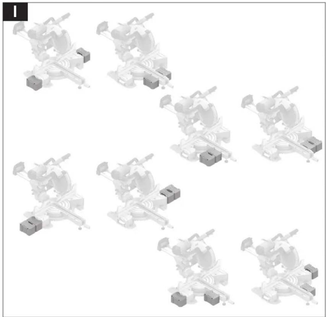
The workpiece supports (16) can be positioned left, right or in front of the power tool. The flexible connector system enables a multitude of extension or expansion variants (see figure I).
- Insert the workpiece support (16) into the openings (40) on the power tool or into the openings (41) of the second workpiece support as required.
▶ Never carry the power tool using the workpiece supports. Only use the transport devices to transport the power tool.
Stationary or flexible mounting
To ensure safe handling, the power tool must be mounted on a flat, stable work surface (e.g. work bench) before use.
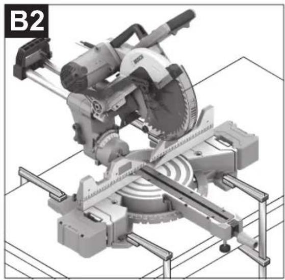
Mounting on a work surface (see figure B1-B2)
- Use suitable screw fasteners to secure the power tool to the work surface. The holes (8) are used for this purpose. or
- Firmly clamp the base of the power tool to the work surface with commercially available screw clamps.
Mounting on a Bosch saw stand
With the height-adjustable legs, Bosch GTA saw stands provide firm support for the power tool on any surface. The workpiece supports of the saw stand are used for underlaying long workpieces.
Read all the warnings and instructions included with the saw stand. Failure to observe the warnings and follow instructions may result in electric shock, fire and/or serious injury.
▶ Assemble the saw stand properly before mounting the power tool. Correct assembly is important to prevent the risk of collapsing.
- Mount the power tool on the saw stand in the transport position.
Flexible installation (not recommended) (see figure C)
If, in exceptional circumstances, it is not possible to mount the power tool on a flat and stable work surface, you can improvise by setting it up with the tilt protector.
▶ Without the tilt protector, the power tool will not be stable and can tip over especially when sawing maximum mitre and/or bevel angles.
- Rotate the tilt protector (12) inwards or outwards until the power tool is positioned straight on the work surface.
Dust/Chip Extraction
The dust from materials such as lead paint, some types of wood, minerals and metal can be harmful to human health. Touching or breathing in this dust can trigger allergic reactions and/or cause respiratory illnesses in the user or in people in the near vicinity.
Certain dusts, such as oak or beech dust, are classified as carcinogenic, especially in conjunction with wood treatment additives (chromate, wood preservative). Materials containing asbestos may only be machined by specialists.
- Use a dust extraction system that is suitable for the material wherever possible.
- Provide good ventilation at the workplace.
- It is advisable to wear a P2 filter class breathing mask.
The regulations on the material being machined that apply in the country of use must be observed.
- Avoid dust accumulation at the workplace. Dust can easily ignite.
The dust/chip extraction system can be blocked by dust, chips or fragments of the workpiece.
- Switch the power tool off and pull the mains plug out of the socket.
- Wait until the saw blade has come to a complete stop.
- Determine the cause of the blockage and eliminate it.
Self-generated dust extraction (see figure D)
For basic chip collection, use the dust bag (43) provided.
- Attach the dust bag (43) to the chip ejector (36).
During sawing, the dust bag must not come into contact with moving tool components.
Always empty the dust bag in good time.
▶ Check and clean the dust bag each time after using.
▶ When sawing aluminium, remove the dust bag to avoid the risk of fire.
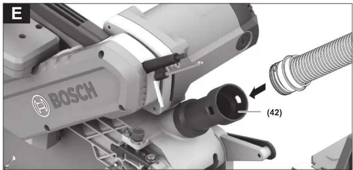
External dust extraction (see figure E)
You can also attach a dust extraction hose (35 mm diameter) to the extraction adapter (42) for extraction.
- Attach the dust extraction adapter (42) to the chip ejector with a twisting motion until it engages above the chip ejector (36) holding ring.
- Connect the dust extraction hose to the extraction adapter (42).
The dust extractor must be suitable for the material being worked.
When extracting dry dust that is especially detrimental to health or carcinogenic, use a special dust extractor.
Cleaning the dust extraction adapter
To ensure optimum extraction, the dust extraction adapter (42) must be cleaned regularly.
- Pull the dust extraction adapter (42) off the chip ejector (36) with a twisting motion.
- Remove workpiece fragments and chippings.
- Reattach the dust extraction adapter to the chip ejector with a twisting motion until it engages above the chip ejector holding ring.
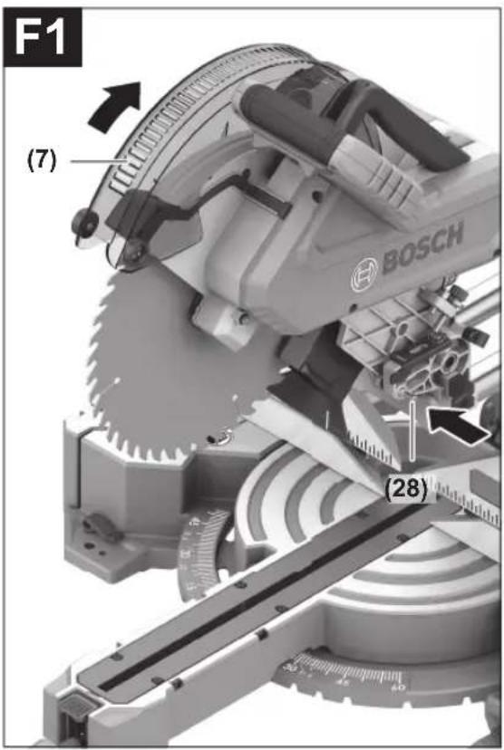
Changing the saw blade (see figures F1-F4)
▶ Pull the plug out of the socket before carrying out any work on the power tool.
▶ Wear protective gloves when fitting the saw blade.
There is a risk of injury when touching the saw blade.
Only use saw blades that have a maximum permitted speed higher than the no-load speed of the power tool.
Only use saw blades that match the specifications given in this operating manual and that have been tested and marked in accordance with EN 847-1.
Only use saw blades that are recommended by the power tool manufacturer and are suitable for use on the material you want to saw. This will prevent the saw teeth overheating when sawing.
Removing the Saw Blade
- Press the transport safety lock (28) inwards to lock the tool arm in the work position.
- Swivel the retracting blade guard (7) to the back and hold it in this position.
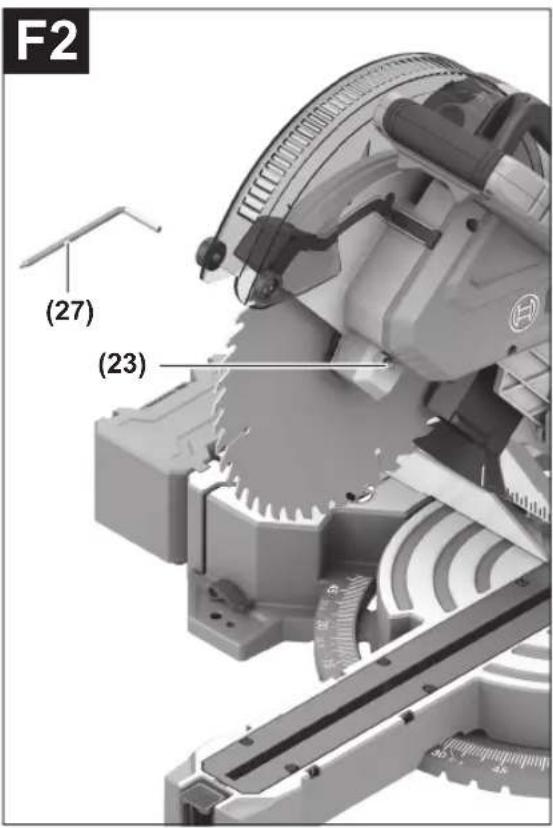
- Turn the hex socket screw (44) using the hex key (27) while pressing the spindle lock (23) until it engages.
- Keep holding the spindle lock (23) and loosen the hex socket screw (44) by turning it clockwise (left-hand thread).
- Remove the clamping flange (45).
- Remove the saw blade (46).
- Slowly push the retracting blade guard back down.
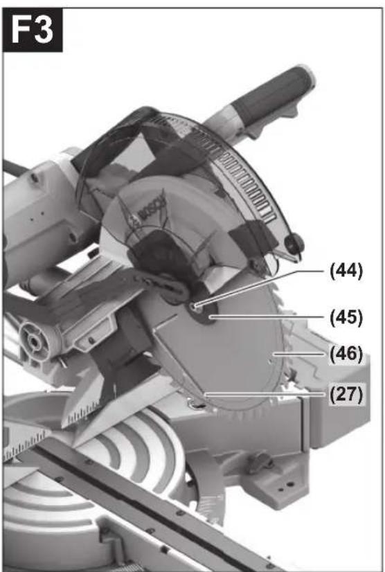
Fitting the saw blade
When fitting the saw blade, make sure that the cutting direction of the teeth (arrow direction on the saw blade) matches the direction of the arrow on the protective guard.
If required, clean all the parts you want to fit before installing them.
- Swivel the retracting blade guard (7) to the back and hold it in this position.
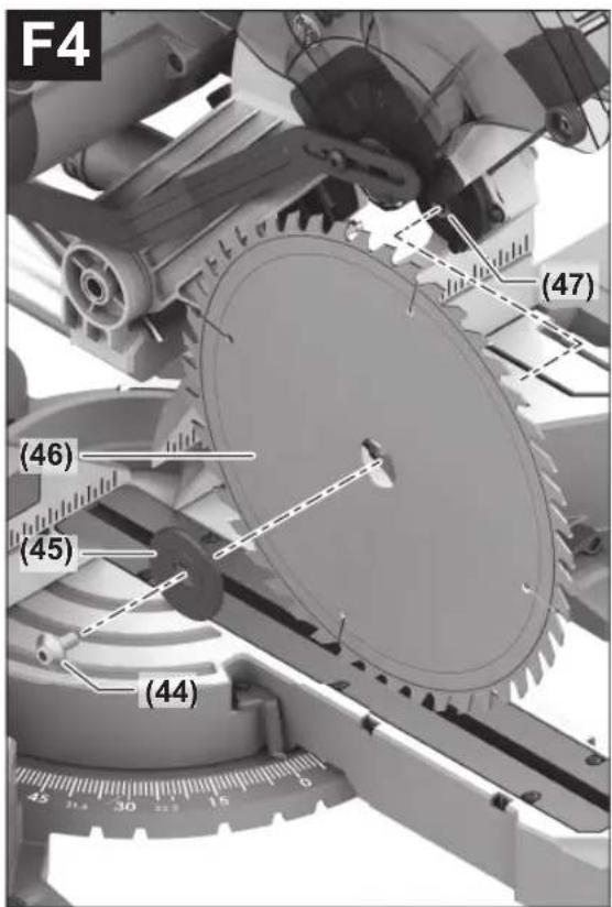
- Place the new saw blade on the inner clamping flange (47).
- Fit the clamping flange (45) and the hex socket screw (44). Press the spindle lock (23) until it engages and tighten the hex socket screw by turning it anticlockwise.
- Slowly push the retracting blade guard back down.
- Press the tool arm down slightly by the handle (4) to release the transport safety lock (28).
- Pull the transport safety lock (28) all the way out. The tool arm can now be moved freely again.
Operation
▶ Pull the plug out of the socket before carrying out any work on the power tool.
▶ Products that are only sold in AUS and NZ: Use a residual current device (RCD) with a nominal residual current of 30 mA or less.
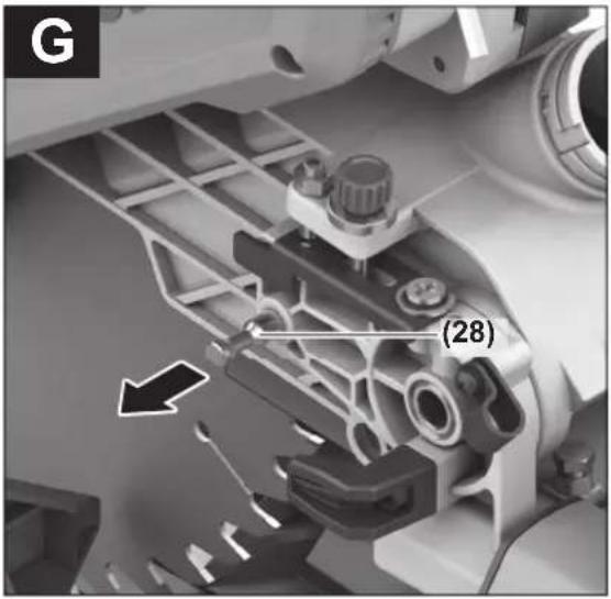
Transport Safety Lock (see figure G)
The transport safety lock (28) makes it easier to handle the power tool when transporting it to various working locations.
Unlocking the power tool (work position)
- Press the tool arm down slightly by the handle (4) to release the transport safety lock (28).
– Pull the transport safety lock (28) all the way out. - Slowly guide the tool arm upwards.
Locking the power tool (transport position)
- Loosen the locking screw (1) if it is clamping the slide device (2) in place. Pull the tool arm fully forward and tighten the locking screw again to lock the slide device.
20 | English
- To lock the saw table (32) in place, tighten the locking knob (11).
- Swing the tool arm downwards by the handle (4) until you can press the transport safety lock (28) completely inwards.
The tool arm is now securely locked and ready for transportation.
Preparing for operation
Extending/Expanding the Saw Table (see figure H-I)
The free end of long and heavy workpieces must have something placed underneath it or be supported.
The saw table can be extended left and right using the saw table extensions (15).
– Pull the clamping lever (31) upwards.
- Pull out the saw table extension (15) to the required length.
- To lock the saw table extension, push the clamping lever (31) back down.
The flexible connector system of the workpiece supports (16) enables a multitude of extension or expansion variants.
- Insert the workpiece support (16) into the openings (40) on the power tool or into the openings (41) of the second workpiece support as required.
▶ Never carry the power tool using the workpiece supports. Only use the transport devices to transport the power tool.
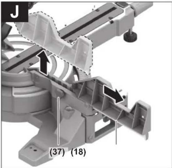
Removing/Moving the Fence (see figure J)
When sawing bevel angles, you must pull the left-hand or right-hand adjustable fence (18) (depending on the cutting direction) outwards, or remove it completely.
- Loosen the wing bolts (37).
- Removing: Lift the adjustable fence (18) upwards and out of the way. Moving: Pull the adjustable fence (18) all the way out.
After sawing the bevel angles, move the adjustable fence (18) back into the starting position and tighten the wing bolts (37).
Clamping the workpiece (see figure K)
To ensure maximum safety while working, the workpiece must always be firmly clamped.
Do not saw workpieces that are too small to clamp firmly.
- Press the workpiece firmly against the fences (17) and (18).
- Insert the supplied screw clamp (19) into one of the corresponding holes (39).
- Loosen the wing bolt (48) and adjust the screw clamp to the workpiece. Tighten the wing bolt again.
- Tighten the threaded rod (49) to fix the workpiece in place.
Releasing the workpiece
- To loosen the screw clamp, turn the threaded rod (49) anticlockwise.
Adjusting mitre angles
- Bring the power tool into the work position.
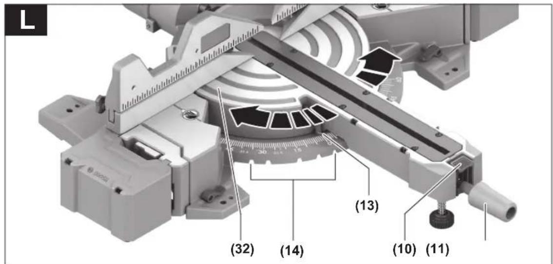
Setting Standard Mitre Angles (see figure L)
For quick and precise setting of commonly used mitre angles, detents (14) are provided on the saw table:
Left Right
0^
52^;45^;31.6^;22.5^;15^15^;22.5^;30^;45^;60^
- Loosen the locking knob (11) if it is tightened.
- Press the lock button (10) down and turn the saw table (32) left or right by the locking knob until the angle indicator (13) shows the standard mitre angle required.
- Release the lock button (10) again. The saw table must be heard to click into the detent.
- Retighten the locking knob (11).
Setting any Mitre Angle
The mitre angle can be set between 52^ (left-hand side) and 60^ (right-hand side).
- Loosen the locking knob (11) if it is tightened.
- Press the lock button (10) down and turn the saw table (32) left or right by the locking knob until the angle indicator (13) shows the mitre angle required.
- Release the lock button (10) again.
- Retighten the locking knob (11).
Adjusting bevel angles
The bevel angle can be set between 47^ (left-hand side) and 47^ (right-hand side).
For quick and precise setting of frequently used bevel angles, fixed positions have been provided for the angles 0°, 33.9° and 22.5°.
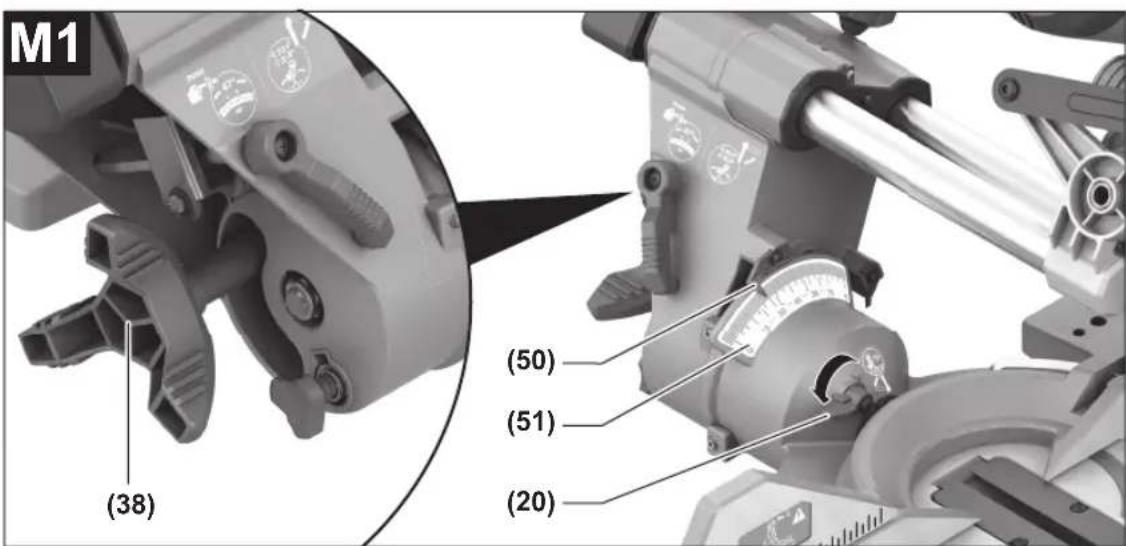
Setting the Right-Hand Bevel Angle Range (0° to 45°) (see figure M1)
- Pull the right-hand adjustable fence (18) all the way out or remove it completely.
- Release the clamping wheel (38).
- Tilt the tool arm on the handle (4) slightly to the left from the 0^ position and push the adjusting lever (20) to the left.
- Use the handle (4) to swivel the tool arm to the right until the angle indicator (50) shows the required bevel angle on the scale (51).
- Hold the tool arm in this position and retighten the clamping wheel (38).
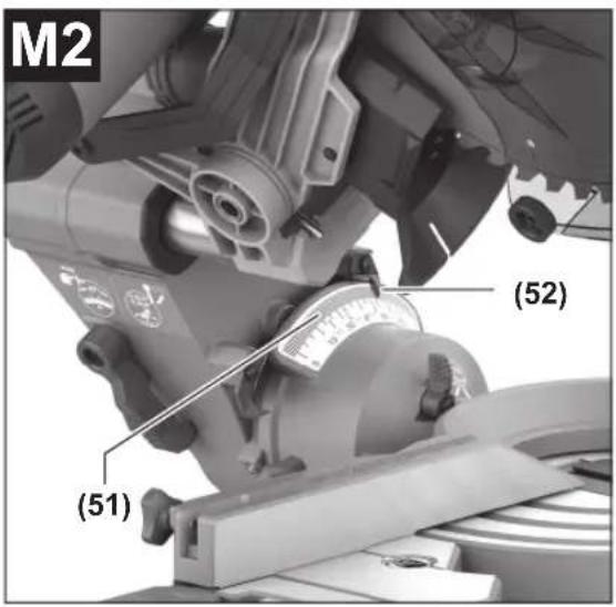
Setting the Left-Hand Bevel Angle Range (0° to 45°) (see figure M2)
- Pull the left-hand adjustable fence (18) all the way out or remove it completely.
- Release the clamping wheel (38).
- Use the handle (4) to swivel the tool arm to the left until the angle indicator (52) shows the required bevel angle on the scale (51).
- Hold the tool arm in this position and retighten the clamping wheel (38).
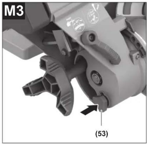
Setting the Complete Bevel Angle Range (see figure M3)
- Ensure that a bevel angle of < 45^ (left or right) is set. Only then can you press the locking button (53).
- Push the locking button (53) fully in. This enables you to use the complete bevel angle range up to 47° (left and right).
Setting Standard Bevel Angles (see figure M4)
- Pull the adjustable fence (18) all the way out or remove it completely.
- Release the clamping wheel (38).
Standard bevel angle 0^ :
- Swivel the tool arm slightly to the left to the 0° position and then to the right until you feel it click into place in the 0° position.
- Retighten the clamping wheel (38).
Standard bevel angle 33.9° and 22.5°:
- Release the locking lever (21) upwards.
- Swivel the tool arm left or right until the angle indicator (52)/(50) shows the required bevel angle. The tool arm must engage securely in place.
- Retighten the clamping wheel (38).
Start-up
▶ Pay attention to the mains voltage. The voltage of the power source must match the voltage specified on the rating plate of the power tool.
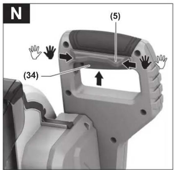
Switching on (see figure N)
- To start the power tool, first push in the lock-off button (5). Then press the on/off switch (34) all the way in and keep it pressed.
Note: For safety reasons, the on/off switch (34) cannot be locked; it must remain pressed during the entire operation.
Switching off
- To switch off, release the on/off switch (34).
Sawing
General sawing instructions
▶ Always tighten the locking knob (11) and the clamping wheel (38) firmly before sawing. Otherwise the saw blade can become wedged in the workpiece.
For all cuts, it must first be ensured that the saw blade at no time can come in contact with the fence, screw clamps or other machine parts. Remove any mounted auxiliary stops or adjust them accordingly.
Protect the saw blade against impact and shock. Do not subject the saw blade to lateral pressure. Only saw materials which are permitted within the scope of the intended use.
Do not saw warped/bent workpieces. The workpiece must always have a straight edge to face against the fence.
The free end of long and heavy workpieces must have something placed underneath it or be supported.
Make sure that the retracting blade guard operates properly and that it can move freely. The retracting blade guard must open when the tool arm is guided downwards. When the tool arm is guided upwards, the retracting blade guard must close again over the saw blade and lock in the uppermost position of the tool arm.
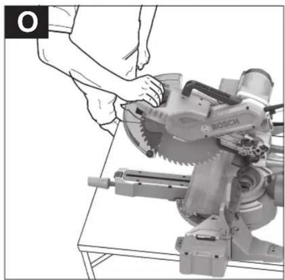
Position of the operator (see figure O)
▶ Do not stand in line with the saw blade in front of the power tool. Always stand to the side of the saw blade. This protects your body against possible kickback.
- Keep hands, fingers and arms away from the rotating saw blade.
- Do not reach one hand across the other when in front of the tool arm.
Sawing with slide movement
- For cuts made using the slide device (2) (wide workpieces), loosen the locking screw (1) if it is tightened.
- Set the required mitre and/or bevel angle as necessary.
- Press the workpiece firmly against the fences (17) and (18).
- Firmly clamp the workpiece as appropriate for its dimensions.
- Pull the tool arm away from the fence (17) until the saw blade is in front of the workpiece.
- Switch the power tool on.
- Slowly guide the tool arm downwards using the handle (4).
- Now push the tool arm towards the fences (17) and (18) and saw through the workpiece with uniform feed.
- Switch off the power tool and wait until the saw blade has come to a complete stop.
- Slowly guide the tool arm upwards.
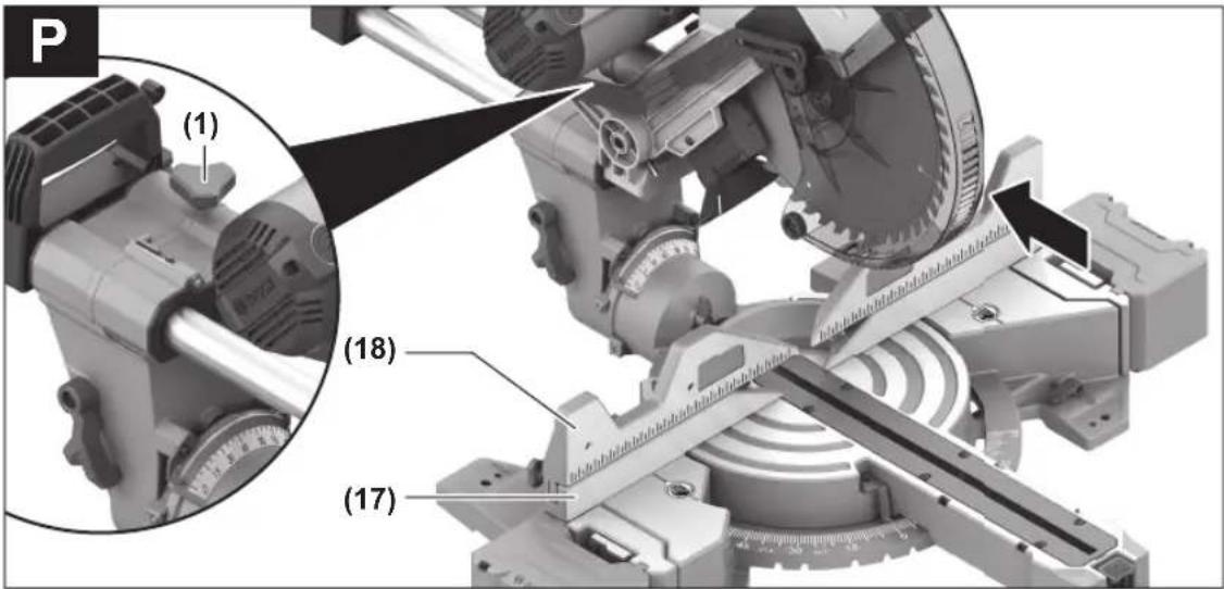
Sawing without slide movement (cutting off) (see figure P)
- For cuts without slide movement (small workpieces), loosen the locking screw (1) if it is tightened. Push the tool arm all the way towards the fence (17) and retighten the locking screw (1).
- Set the required mitre and/or bevel angle as necessary.
- Press the workpiece firmly against the fences (17) and (18).
- Firmly clamp the workpiece as appropriate for its dimensions.
- Switch the power tool on.
- Slowly guide the tool arm downwards using the handle (4).
- Saw through the workpiece applying uniform feed.
22 | English
- Switch off the power tool and wait until the saw blade has come to a complete stop.
- Slowly guide the tool arm upwards.
Practical advice
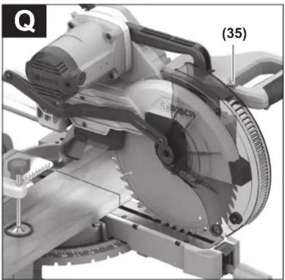
Marking the Cutting Line (see figure Q)
The worklight improves visibility in the immediate work area and also indicates the cutting line of the saw blade. This allows for exact positioning of the workpiece for sawing, without having to open the retracting blade guard.
- Mark the required cutting line on the workpiece.
- Switch on the worklight with the switch (35).
- Guide the tool arm down in front of the workpiece. The saw blade's shadow will appear on the workpiece. This shadow line indicates the material that will be removed by the saw blade during cutting.
- Align your mark on the workpiece with the shadow line.
Permissible workpiece dimensions
Maximum workpiece dimensions:
| Mitre angle Bevel angle Height x width [mm] |
| 0° 0° 105 x 340 |
| 45° 0° 105 x 245 |
| 0° 45° (left) 70 x 340 |
| 45° 45° (left) 70 x 245 |
| 0° 45° (right) 48 x 340 |
| 45° 45° (right) 48 x 245 |
Maximum cutting depth (0°/0°): 105 mm
Sawing workpieces of the same length (see figure R)
The left or right length stop (29) can be used for easily sawing workpieces of the same length.
- Turn the length stop (29) upwards.
- Set the saw table extension (15) to the required workpiece length.
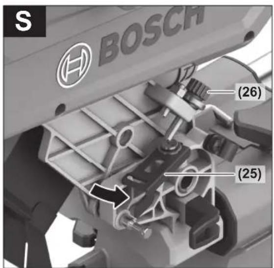
Adjusting the depth stop (sawing the groove) (see figure S)
The depth stop needs to be adjusted if you wish to saw a groove.
- Swivel the depth stop (25) outwards.
- Swivel the tool arm by the handle (4) into the required position.
- Turn the adjusting screw (26) until the end of the screw touches the depth stop (25).
- Slowly guide the tool arm upwards.
Special workpieces
When sawing curved or round workpieces, these must be especially secured against slipping. At the cutting line, there should be no gap between the workpiece, fence and saw table.
If necessary, you will need to manufacture special fixtures.
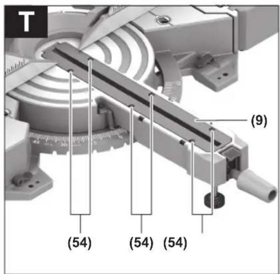
Replacing insert plates (see figure T)
The insert plate (9) can become worn after long use of the power tool.
Replace a defective insert plate.
- Bring the power tool into the work position.
- Unscrew the screws (54) using a commercially available cross-headed screwdriver and remove the old insert plate (9).
- Insert the new insert plate and screw the screws (54) in tight again.
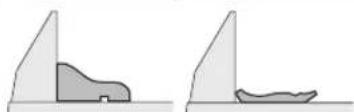
Working on mouldings
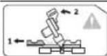
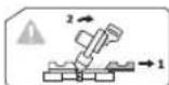
Mouldings can be sawn in two different ways:
| Positioning of workpiece | Base moulding Crown moulding |
| - Placed against the fence | 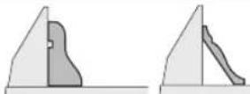 |
| - Lying flat on the saw table | 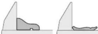 |
Furthermore, you can cut with or without the slide movement depending on the width of the moulding.
Always check the set mitre and/or bevel angle first by making trial cuts in scrap wood.
Checking and Adjusting the Basic Settings
To ensure precise cuts, the basic settings of the power tool must be checked and adjusted as necessary after intensive use.
Experience and suitable special tools are required for this.
A Bosch after-sales service point will handle this work quickly and reliably.
Aligning the fence
- Bring the power tool into the transport position.
- Loosen the locking knob (11) if it is tightened.
- Push the lock button (10) down and turn the saw table (32) to the 0° detent (14).
- Release the lock button (10) again. The saw table must be heard to click into the detent.
- Remove the adjustable fences (18).
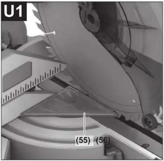
Checking (see figure U1)
- Position the set square (55) with the 90^ angle flush with the saw blade (46) between the fence (17) and the saw blade on the saw table (32).
The leg of the set square must be flush with the fence along its entire length.
Setting (see figure U2)
- Loosen all hex socket screws (56) with the hex key (27) provided.
- Rotate the fence (17) until the set square is flush along its entire length.
- Retighten the screws.
Aligning the Angle Indicator (Vertical) (see figure V)
- Swivel the tool arm slightly to the left to the 0^ position and then to the right until you feel it click into place in the 0^ position.
Checking
The angle indicators (50) and (52) must be in line with the 0^ marks on the scale (51).
Setting
- Undo the screws (57) with a cross-headed screwdriver and align the angle indicators along the respective 0^ mark.
- Retighten the screws.
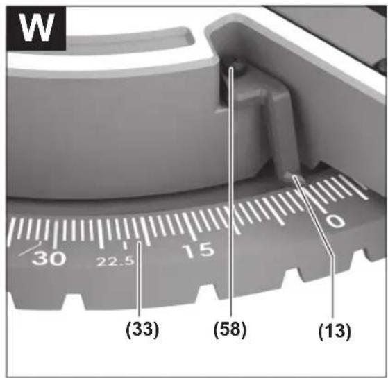
Aligning the mitre angle indicator (see figure W)
- Bring the power tool into the work position.
- Turn the saw table (32) to the 0^ detent (14). The lever must be felt to engage in the detent.
Checking
The angle indicator(13) must be in line with the 0^ mark of the scale (33).
Setting
- Loosen the screw (58) using a cross-headed screwdriver and align the angle indicator along the 0^ mark.
- Retighten the screw.
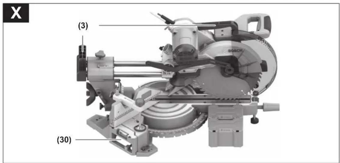
Transporting the Power Tool (see figure X)
Before transporting the power tool, the following steps must be carried out:
- Loosen the locking screw (1) if it is tightened. Pull the tool arm fully forwards and retighten the locking screw.
- Make sure that the depth stop (25) is pressed all the way in and that the adjusting screw (26) fits through the recess without touching the depth stop when moving the tool arm.
- Bring the power tool into the transport position.
- Remove all accessories that cannot be securely fitted to the power tool. If possible, transport unused saw blades in an enclosed container.
- Carry the power tool by the transport handle (3) or hold it by the recessed handles (30) on the sides of the saw table.
▶ Only use the transport devices to transport the power tool and never the protective devices or workpiece supports.
Maintenance and Service
Maintenance and Cleaning
▶ Pull the plug out of the socket before carrying out any work on the power tool.
▶ To ensure safe and efficient operation, always keep the power tool and the ventilation slots clean.
In order to avoid safety hazards, if the power supply cord needs to be replaced, this must be done by Bosch or by an after-sales service centre that is authorised to repair Bosch power tools.
The retracting blade guard (7) must always be able to move freely and retract automatically. It is therefore important to keep the area around the retracting blade guard clean at all times.
Always remove dust and chips after working by blowing out with compressed air or using a brush.
Clean the guide roller (22) regularly.
Noise reduction measures
Measures implemented by the manufacturer:
- Soft start
– Provided with a saw blade specially developed for noise reduction
Measures implemented by the operator:
– Low-vibration mounting on a stable work surface - Use of saw blades with noise-reducing functions
- Regular cleaning of the saw blade and power tool
After-Sales Service and Application Service
Malaysia
Tel.: (03) 79663194

You can find our service addresses and links to the repair service and spare parts ordering at www.bosch-pt.com/serviceaddresses
In all correspondence and spare parts orders, please always include the 10-digit article number given on the nameplate of the product.
Disposal
The power tool, accessories and packaging should be recycled in an environmentally friendly manner.
Do not dispose of power tools along with household waste.
Français
natural_image
Diagram of a thermometer with arrows indicating force direction (no text or labels)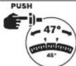
natural_image
Two abstract geometric diagrams showing a shaded region between two triangular forms, one with a small rectangular cutout and the other with a sloped edge (no text or symbols)- 平放在锯台上

www.bosch-pt.com/serviceaddresses
natural_image
Two diagrams showing a mechanical or structural component with shaded areas, no text or symbols present.- 平放在鋸台上
natural_image
Two abstract geometric shapes with shaded regions, no text or symbols presentwww.bosch-pt.com/serviceaddresses
即可查詢我們的服務地址和維修服務以
及零件訂購連結。