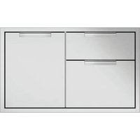
ADR2-36 - Barbecue DCS - Free user manual and instructions
Find the device manual for free ADR2-36 DCS in PDF.


User questions about ADR2-36 DCS
0 question about this device. Answer the ones you know or ask your own.
Ask a new question about this device
Download the instructions for your Barbecue in PDF format for free! Find your manual ADR2-36 - DCS and take your electronic device back in hand. On this page are published all the documents necessary for the use of your device. ADR2-36 by DCS.
USER MANUAL ADR2-36 DCS
text_image
DCS by Fisher&PaykelProfessional Access Drawers
ADR models
Installation instructions
and User guide
A MESSAGE TO OUR CUSTOMERS
Thank you for selecting these DCS by Fisher & Paykel Professional Access Drawers. Because of this product's unique features we have developed this Installation Guide. It contains valuable information on how to properly install and maintain your new Professional Access Drawers for years of safe and enjoyable use.
To help serve you better, please fill out and submit your Product Registration by visiting our website at www.dcsappliances.com and selecting "Customer Care" on the home page and then select "Product Registration". In addition, keep this guide handy, as it will help answer questions that may arise as you use your new Access Drawers.
For your convenience, product questions can be answered by a DCS by Fisher & Paykel Customer Care Representative at 1-888-936-7872, or email: customer.care@fisherpaykel.com.
Note: Please write the model, code, and serial numbers on this page for reference (located on the sticker on the rear brace in the tank side - see Fig. 04).
Model number Code Serial number
NOTE: Inspect the product to verify that there is no shipping damage. If any damage is detected, call the shipper and initiate a damage claim. DCS by Fisher & Paykel is not responsible for shipping damage.
DO NOT discard any packing material (box, pallet, straps) until the unit has been inspected.

WARNING
- Do Not store or use gasoline or other flammable vapors and liquids inside or in the vicinity of this or any other appliance.
- An LP cylinder not connected for use shall not be stored inside or in the vicinity of this unit.

FOR YOUR SAFETY
- Do not allow children or pets to play in or around the Access Drawers.
- Clean the Access Drawers regularly using a mild dish washing liquid and water.
- To maintain the exterior appearance, apply a stainless steel polish to the outside surfaces on a regular basis.
- Sanitize the Access Drawers surfaces each season as necessary.
- To prevent the formation of mold or mildew, do not store cloth napkins or tablecloths in the Access Drawers for long periods.
- Cooking utensils that are stored in the Access Drawers should be stored in sealable plastic bags and/or washed each time before re-use.
- To prevent personal injury or damage to the drawers, do not overload them. The maximum rating per drawer is 75 pounds.

WARNING

- Closing drawers may cause injury to your hands or fingers.
• Always close or open drawers using their handles. - Be sure to keep hands away from drawer edges when opening or closing drawers.
TABLE OF CONTENTS
SAFETY PRACTICES & PRECAUTIONS 3
MODEL IDENTIFICATION & DIMENSIONS 4
SHIPPING INSPECTION 5
CABINET PREPARATION 5
INSTALLATION
Make Cutout and Installing Support Structure - 6
Proud installation
Make Cutout and Installing Support Structure - 8
Flush installation
Removing Drawers 10
Slide in Access Drawers and Mount to Support Structure 10
Re-installing Drawers 11
SAFETY PRACTICES AND PRECAUTIONS
- Begin by insuring proper installation and servicing.
- Follow the installation instructions in this manual.
- To extend the service life of your product, be sure to follow the use and care guidelines in this manual.

WARNING:
Do not store items of interest to children above or on the inside of any appliance. Children could be seriously injured if they should climb onto or into the appliance to reach these items.
PLEASE RETAIN THIS MANUAL FOR FUTURE REFERENCE
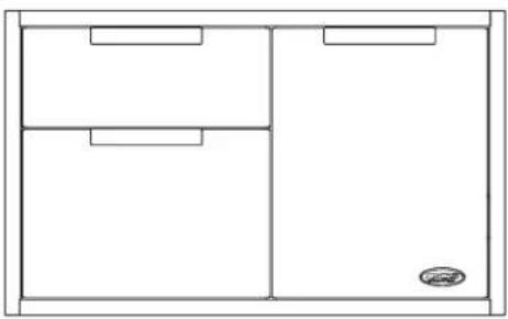
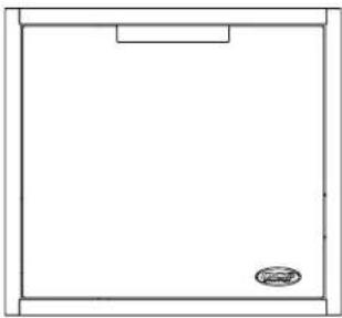
MODEL IDENTIFICATION & DIMENSIONS
ADR2-48
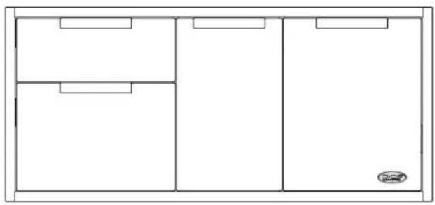
natural_image
Simple line drawing of a rectangular room layout with three internal compartments and a small car icon at the bottom right (no text or symbols)ADR2-30
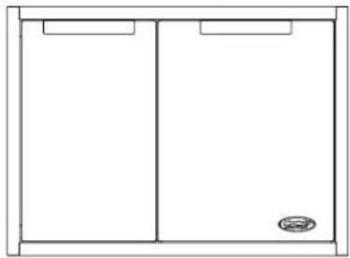
natural_image
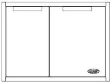
Simple line drawing of a two-panel cabinet or enclosure with no text, numbers, or symbolsADR2-36
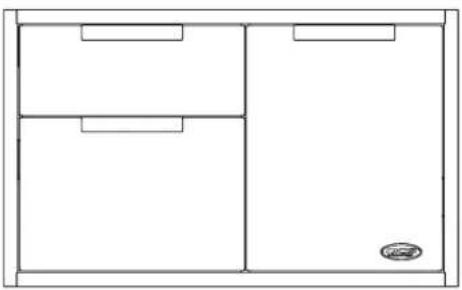
natural_image
Simple line drawing of a three-panel cabinet or storage unit with no text, numbers, or symbolsADR2-24
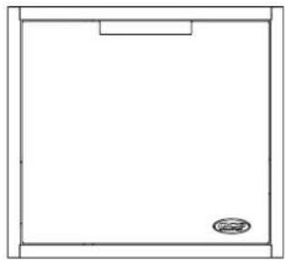
natural_image
Simple line drawing of a rectangular frame with a small oval detail on the bottom right corner (no text or symbols)Fig. 1
text_image
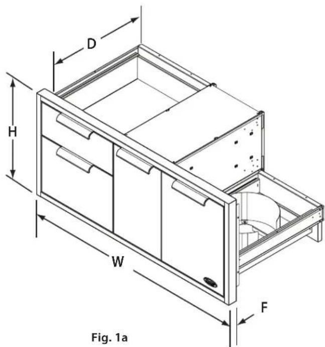
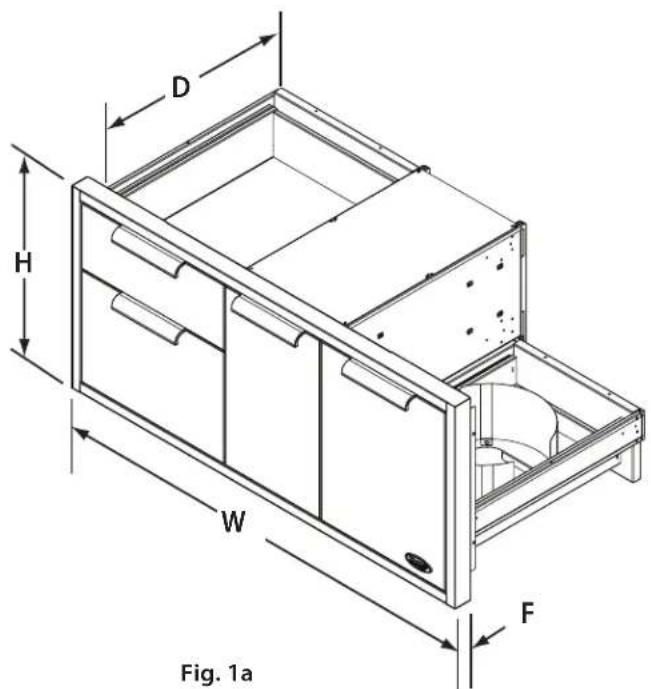
D H W F Fig. 1a| DIMENSIONS | ||||
| Model | DWHF | |||
| ADR2-48 23-1/2" 48" | 21-7/8" | 2" | ||
| ADR2-36 23-1/2" 36" | 21-7/8" | 2" | ||
| ADR2-30 23-1/2" 30" | 21-7/8" | 2" | ||
| ADR2-24 23-1/2" 24" | 21-7/8" | 2" | ||
SHIPPING INSPECTION
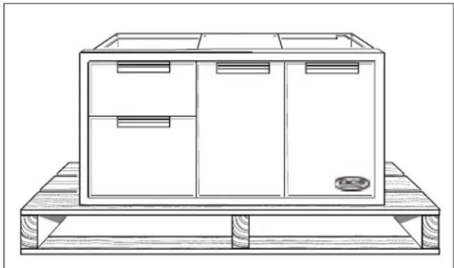
- Inspect the Access Drawers to verify that there is no shipping damage.
- If any damage is detected, call the shipper and initiate a damage claim. DCS by Fisher & Paykel is not responsible for shipping damage.
NOTE: Do not discard any packing material (box, pallet, straps) until the unit has been inspected.
■ Operate the drawers to be sure they glide smoothly.
■ Examine the drawer fronts to be sure there are no dents or scratches or discoloring.
natural_image
Line drawing of a cabinet with drawers and storage compartments on a wooden shelf (no text or symbols)Fig. 2
CABINET PREPARATION
■ Cabinet face should be clean and flat.
■ All angles must be at 90 and plumb.
■ Support structure must be resistant to moisture damage.
■ All gas lines and plumbing must be done before installing access drawers.
■ Do not use any harsh products (acid, solvent, sealers) around this unit.
■ Any cabinet and/or ground preparations must be completed prior to installation.
INSTALLATION
MAKE CUTOUT AND INSTALL SUPPORT STRUCTURE - PROUD INSTALLATION
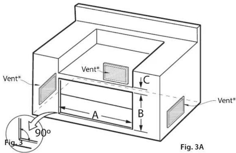
- Make a cut-out in your cabinet or island with the following dimensions (Fig. 3A):
NOTE: Each corner of the cutout should be 90° for the Access Drawers to fit properly.
text_image
Vent* Vent* C A B Vent* Vent* Fig. 3 90° Fig. 3A* Island installation to use minimum of 3 vents providing 10 sq. in. per vent (typical).
| CUTOUT DIMENSIONS | |||
| Model | A(-0,+1/8") | B(-0,+1/8") | C |
| ADR2-48 46" 20" 1.0" min. | |||
| ADR2-36 34" 20" 1.0" min. | |||
| ADR2-30 28" 20" 1.0" min. | |||
| ADR2-24 22" 20" 1.0" min. | |||
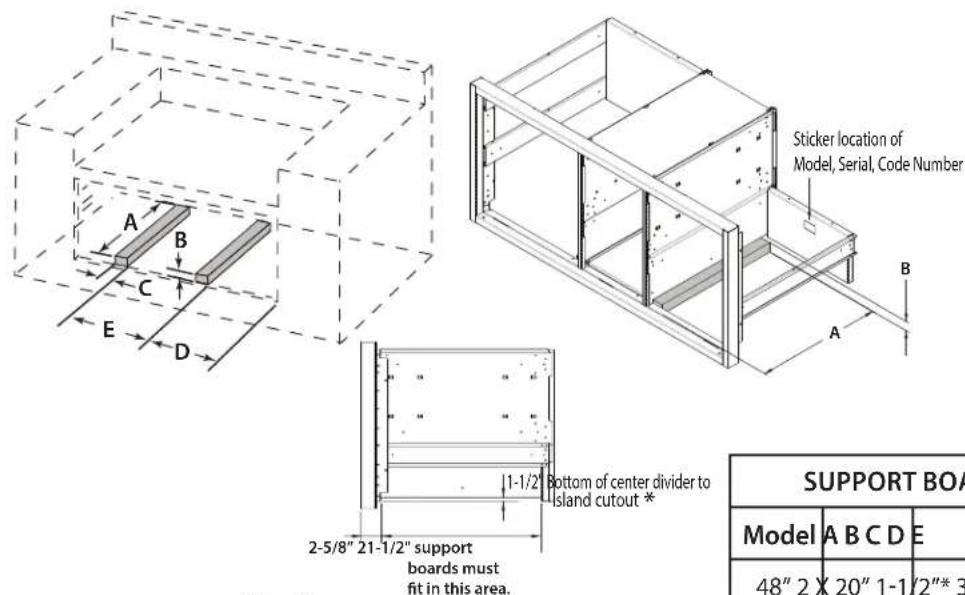
- Place 2 X 4s to provide support for the Access Drawers structure in the locations indicated in Fig. 4A.
- Board lengths are provided in the table Fig. 5A.
INSTALLATION
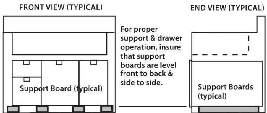
To ensure proper drawer operation, be sure your support boards are flat & level.
text_image
Sticker location of Model, Serial, Code Number A B C D E F A B Bottom of center divider to Island cutout * 2-5/8" 21-1/2" support boards must fit in this area. SUPPORT BOA Model A B C D E 48" 2 X 20" 1-1/2"* 3Fig. 4A
*Dependent on application. Top of support boards must be 1/2" above the bottom edge of the cutout.
| SUPPORT BOARD DIMENSIONS | |||||
| Model | A B C D E | ||||
| 48" 2 X | 20" 1-1 | /2"* 3-1/2" | min. 14 12 | ||
| 36" 20" | 1-1/2"* | 3-1/2" | min. 14 - | ||
| 30" 2 X | 20" 1-1 | /2"* 3-1/2" | min. 14 12 | ||
| 24" 20" | 1-1/2"* | 3-1/2" | min. 14 - | ||
Fig. 5A
- When installing your support boards, be sure they are level.
- Ensure that the bottom of the center divider rests on top of the support boards as shown (Fig. 4A).
text_image
FRONT VIEW (TYPICAL) END VIEW (TYPICAL) For proper support & drawer operation, insure that support boards are level front to back & side to side. Support Board (typical) Support Boards (typical)Fig. 6A
INSTALLATION
MAKE CUTOUT AND INSTALL SUPPORT STRUCTURE - FLUSH INSTALLATION
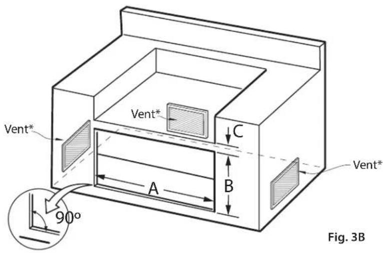
- Make a cut-out in your cabinet or island with the following dimensions:
NOTE: Each corner of the cutout should be 90° for the Access Drawers to fit properly.
text_image
Vent* Vent* C A B 90° Vent* Vent* Fig. 3B* Island installation to use minimum of 3 vents providing 10 sq. in. per vent (typical).
| CUTOUT DIMENSIONS | ||||
| Model | A(-0,+1/8") | B(-0,+1/8") | C | D |
| ADR2-48 48 | 3/16" 23 - 1 | 1/16" 1.0" min. | 1.0" min. | |
| ADR2-36 36 | 3/16" 23 11 | /16" 1.0" min. | 1.0" min. | |
| ADR2-30 30 | 3/16" 23 11 | /16" 1.0" min. | 1.0" min. | |
| ADR2-24 24 | 3/16" 23 11 | /16" 1.0" min. | 1.0" min. | |
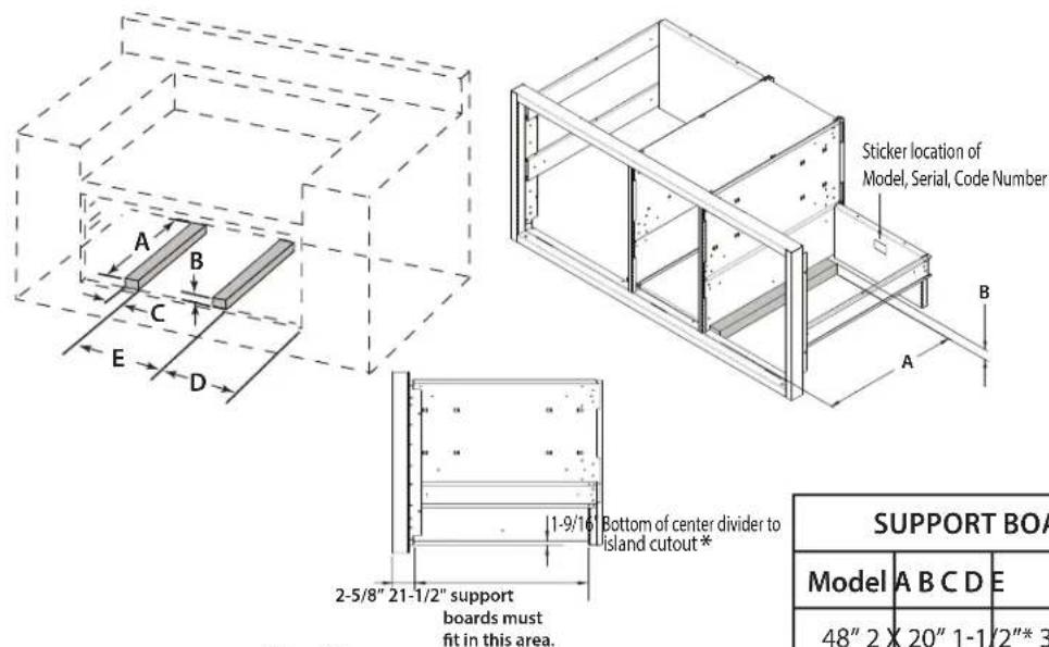
- Place 3" X 4"s to provide support for the Access Drawers structure in the locations indicated in the figure opposite (Fig. 4B).
- Board lengths are provided in the table opposite (Fig. 5B).
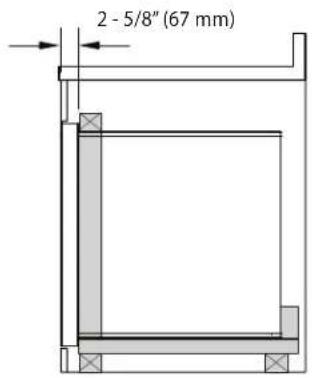
Note: The frame should locate the Access Drawer assembly in the center of the cutout, and be fastened to the enclosure such that the unit is reliably secured in place.
text_image
2 - 5/8" (67 mm)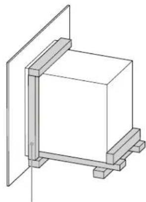
natural_image
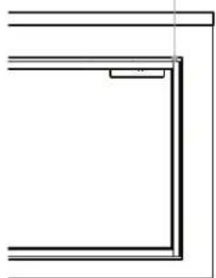
Pure technical line drawing of a 3D rectangular block mounted on a frame, with no text or symbols present.A frame should be constructed 2" (51 mm) setback from the front face of the product to both push the product up against and conceal the cutout clearance around the front frame.
Important!
Do not seal the product in with silicone caulk or similar. Doing so will result in the product being difficult to remove for servicing.
Minimum 3/16" (4 mm) cutout clearance around front frame
natural_image
Pure geometric lines forming an L-shape with a small rectangular notch (no text or symbols)INSTALLATION
To ensure proper drawer operation, be sure your support boards are flat & level.
text_image
Sticker location of Model, Serial, Code Number A B C D E A B 1-9/16 Bottom of center divider to island cutout * 2-5/8" 21-1/2" support boards must fit in this area. SUPPORT BOA Model A B C D E 48" 2 X 20" 1-1/2"* 3Fig. 4B
*Dependent on application. Top of support boards must be 1-9/16" above the bottom edge of the cutout.
| SUPPORT BOARD DIMENSIONS | |||||
| Model | A B C D E | ||||
| 48" 2 X | 20" 1-1 | /2"* 3-1/2" | min. 15 12 | ||
| 36" 20" | 1-1/2"* | 3-1/2" | min. 15 - | ||
| 30" 2 X | 20" 1-1 | /2"* 3-1/2" | min. 15 12 | ||
| 24" 20" | 1-1/2"* | 3-1/2" | min. 15 - | ||
Fig. 5B
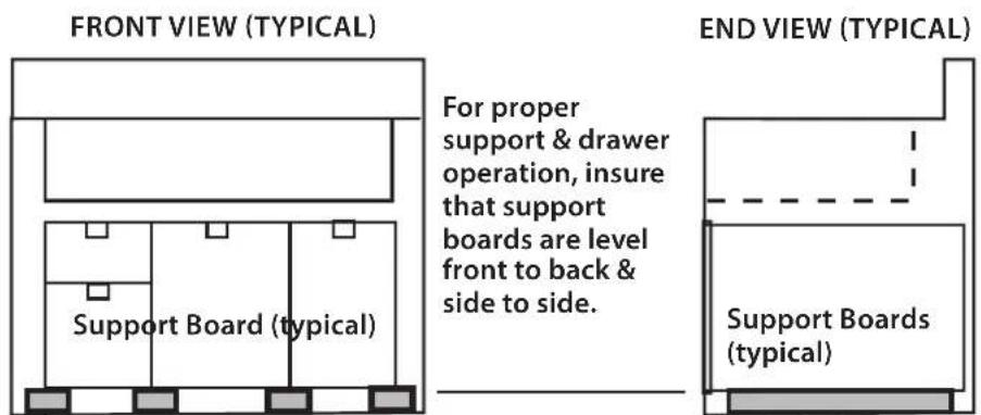
Leave a 2" set back for the flush installation.
text_image
FRONT VIEW (TYPICAL) For proper support & drawer operation, insure that support boards are level front to back & side to side. END VIEW (TYPICAL) Support Board (typical) Support Boards (typical)Fig. 6B
INSTALLATION
REMOVING DRAWERS
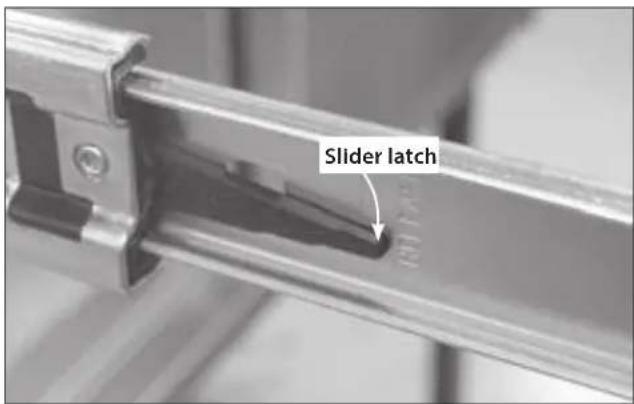
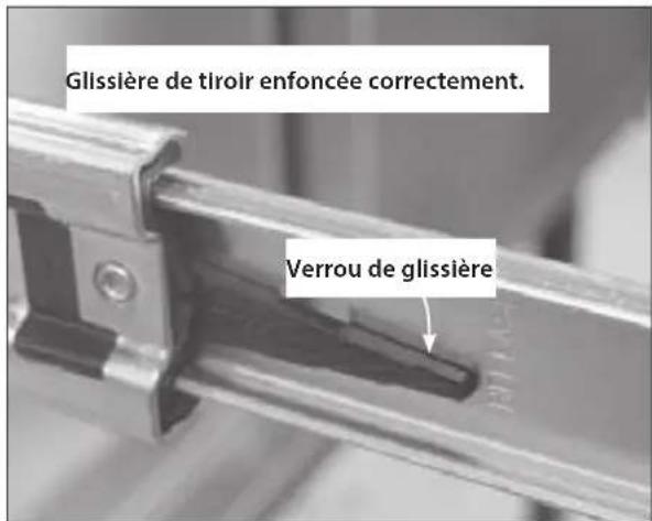
- Once the unit has been inspected, remove the drawers by pulling them out until their slider latch is visible. Carefully push the latch down on the left side while pulling up on the right side and pull the drawers completely out of the frame (Fig. 7).
- To prevent damage to surfaces, place the drawers on a stable surface on a protective towel or table cloth.
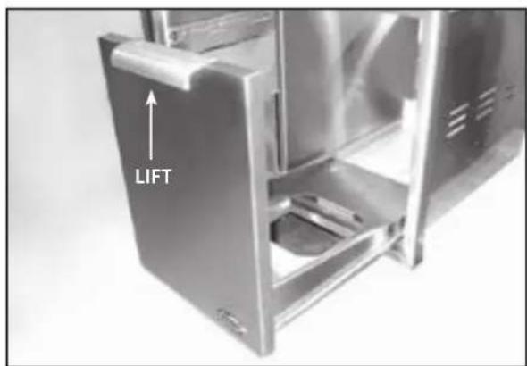
TO REMOVE THE ADR2-24 DRAWER, pull the drawer out and lift the end by the handle to disengage the rollers (Fig. 8).
text_image
Slider latchFig. 7
text_image
LIFTFig. 8
SLIDE IN FRAME AND MOUNT TO SUPPORT STRUCTURE
- With the help of an assistant, lift the unit and slide it into the cabinet cutout. Adjust for level and fit.
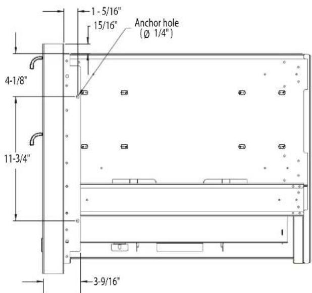
- Locate mounting holes on the frame (Fig. 9 and views). Secure the unit using screws suited for the type of cabinet material.
NOTE: Depending on the wall thickness and location of mounting holes, an additional board may be required to properly receive the screws.
text_image
1 - 5/16" 15/16" Anchor hole (Ø 1/4") 4-1/8" 11-3/4" 3-9/16"Fig. 9
INSTALLATION
RE-INSTALLING DRAWERS
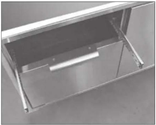
- Re-install the drawers by extending their guides as shown in Fig. 10.
- While holding the drawer parallel to the cabinet, carefully align & engage the ends of the glides. Slide the drawer in about an inch so that the glides are supporting the back of the drawer (Fig. 11).
natural_image
Interior view of a stainless steel cabinet or enclosure with open door and metal frame (no visible text or symbols)Fig. 10

text_image
Drawer Glide properly Engaged. Slider latchFig. 11
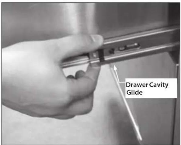
- While holding the drawer up by the handle, pull the glides from the drawer cavity out over the drawer glide until they click (Fig. 12).
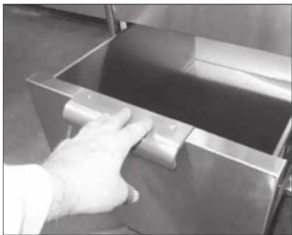
- As you push the drawers in, you will encounter moderate resistance. Continue to push the drawer all the way in to complete the engagement process. The drawer will now glide smoothly in & out with light effort (Fig. 13).
text_image
Drawer Cavity GlideFig. 12
natural_image
Hand in white glove operating a stainless steel kitchen counter (no visible text or symbols)Fig. 13
INSTALLATION
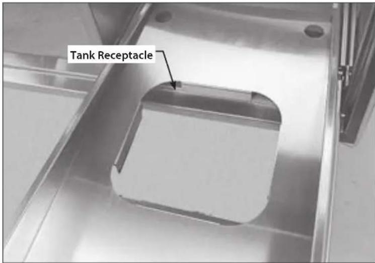
- Your LP tank will be installed in the recess provided in the bottom of the right compartment (Fig. 14).
text_image
Tank ReceptacleFig. 14
- When connecting the LP tank to your grill be certain that all connections are tight. Once gas connections are made, test for gas leaks.
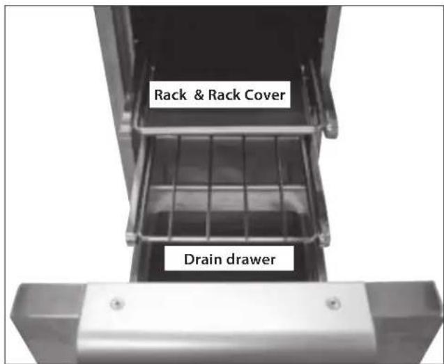
- On models so equipped, install the two (2) racks provided into the opening by sliding them onto the rollers on the sidewalls of the center cavity (Fig. 15).
text_image
Rack & Rack Cover Drain drawerFig. 15
CARE & MAINTENANCE
The Access Drawers are made from corrosion-resistant and non-magnetic stainless steel. All parts of the Access Drawers can be cleaned with hot soapy water, rinsed, dried and buffed to a shine with a soft, heavy cloth. Always try this first, as it is the mildest cleaning procedure. There are many different stainless steel cleaners available. Always use the mildest cleaning procedure first, scrubbing in the direction of the grain to avoid marring the surface. The cleaner will be more effective when used in the direction of the grain (polish lines).
- Some brands of cleaners of the same type are harsher than others, read their directions. A scent or a propellant can make a difference in the product, read the ingredients. Try on a small area first.
- To touch up noticeable scratches in the stainless steel, sand very lightly with wet 100 grit emery paper in the direction of the grain.
- Specks of grease can gather on the surfaces of the stainless steel and bake on to the surface and give the appearance of rust.
For removal use an abrasive pad (Scotch Brite is good) in conjunction with a stainless steel cleaner. Always rub in the direction of the grain.
- Use only clean sponges, soft cloths, paper towels, plastic non-metal soap pads for cleaning or scouring as recommended in this section. (Use only soap pads with soap still in them. An empty pad can scratch.)
- Be sure to rinse all parts thoroughly and to wipe dry to avoid water marks.
NOTE: Stainless steel tends to corrode in presence of chlorides and sulfides especially in coastal areas. To ensure corrosion prevention, wash all stainless steel surfaces every 3-4 weeks with fresh water and stainless cleaner.

text_image
Lubrication points (Use silicone spray annually)Fig. 16
BRAND NAME CLEANERS
In this section on cleaning, the use of name brands is intended only to indicate a type of cleaner. This does not constitute an endorsement. The omission of any name brand cleaner does not imply its adequacy or inadequacy. Many products are regional in distribution and can be found in local markets and department stores.
MAINTENANCE
After cleaning, use a stainless steel polish, such as Stainless Steel Magic ^® applied to the drawer and handle surfaces. To maintain the smooth operation of the drawers, spray the bearing areas with silicone spray lubricant annually (Fig. 16).
ACCESSORIES
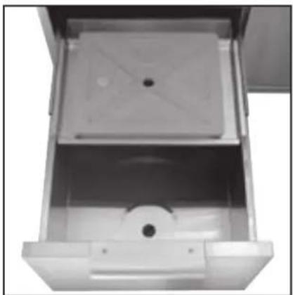
- Freezer Pack (optional, Kit #70696A)(Fig. 17). This cold-assist Ice Pack (BLUICE) fits snugly into the roller rack found on the 30" and 48" Access Drawers and CAD carts.
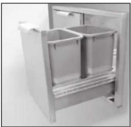
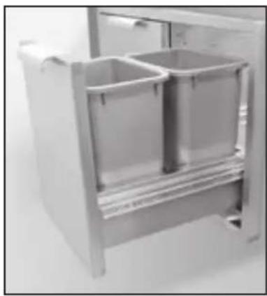
- Waste Basket Holder (optional, Kit #70906)(Fig. 18)
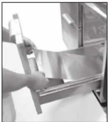
- Bottom Cover (optional, Kit #70907)(Fig. 19)
natural_image
Interior view of a stainless steel filing cabinet with open door and side panel (no visible text or symbols)Fig. 17 - Freezer Pack (optional)
natural_image
Interior view of a stainless steel recycling bin with two internal compartments (no text or symbols visible)Fig. 18 - Waste Basket Holder (optional)
NOTE: To order these accessories, please contact Fisher & Paykel Customer Care at 1-888-936-7872.
natural_image
Person handling a metal sheet or sheet with a glass container (no visible text or symbols)Fig. 19 - Bottom Cover (optional)
SERVICE
For warranty service, please contact your local service provider or DCS Customer Care Representative at (888) 936-7872 or go to our website at www.dcsappliances.com and choose "Customer Care" to find your nearest Authorized Service Center. Before you call, please have the following information ready:
■ Model Number (located on the sticker on the rear brace in the tank side - see Fig. 04).
Serial Number (located on the sticker on the rear brace in the tank side - see Fig. 04).
Code Number (located on the sticker on the rear brace in the tank side - see Fig. 04).
Date of installation
■ A brief description of the problem
Your satisfaction is of the utmost importance to us. If a problem cannot be resolved to your satisfaction, please write or email us at:
Write:
Fisher & Paykel Appliances, Inc.
Attention: DCS Customer Care
DCS Customer Care
695 Town Center Drive, Suite 180 Costa Mesa.
CA 92626-1902 USA
email: customer.care@fisherpaykel.com
A L'INTENTION DE NOS CLIENTS
- Closing drawers may cause injury to your hands or fingers.
• Always close or open drawers using their handles.
- Be sure to keep hands away from drawer edges when opening or closing drawers.
TABLE DES MATIERES
MESURES DE SECURITE ET DE PRECAUTION 2
IDENTIFICATION DU MODELE ET DIMENSIONS 3
INSPECTION APRES LIVRAISON 4
PRÉPARATION DE L'ÉLÉMENT 5
INSTALLATION
natural_image
Simple line drawing of a four-panel room layout with no text or symbolsADR2-30
natural_image
Simple line drawing of a two-panel cabinet or enclosure with no text, numbers, or symbols.ADR2-36
natural_image
Simple line drawing of a three-panel cabinet or storage unit with no text or symbolsADR2-24
natural_image
Simple line drawing of a rectangular frame with a small oval at the bottom (no text or symbols)Fig. 1
text_image
D H W F Fig. 1a| DIMENSIONS/COTES | ||||
| MODELE | D W H F | |||
| ADR2-48 | 59,7 cm | 121,9cm 55,6 cm 5,1 cm | ||
| ADR2-36 | 59,7 cm | 91,4 cm 55,6 cm 5,1 cm | ||
| ADR2-30 | 59,7 cm | 76,2 cm 55,6 cm 5,1 cm | ||
| ADR2-24 | 59,7 cm | 61 cm 55,6 cm 5,1 cm | ||
INSPECTION APRES LIVRAISON
natural_image
Line drawing of a three'-enclosed storage cabinet on a wooden platform (no text or symbols)Fig. 2
PRÉPARATION DE L'ÉLÉMENT
natural_image
Pure technical line drawing of a 3D rectangular block mounted on a base frame, without any text, numbers, or symbols.natural_image
Interior view of a stainless steel-framed cabinet or enclosure with open door and internal compartments (no text or symbols visible)Fig. 10 Fig. 11
natural_image
Close-up of a hand pressing down on a metallic industrial machine component (no visible text or symbols)Fig. 13
INSTALLATION
natural_image
Interior view of a stainless steel filing cabinet with open door and side panel (no visible text or symbols)Fig. 17 Freezer Pack (option)
natural_image
Interior view of a modern kitchen drawer with two empty plastic bins (no text or symbols visible)natural_image
Person handling a metal shelf with a hand adjusting the tray (no visible text or symbols)Fisher & Paykel Appliances, Inc.
Attention : DCS Customer Care
DCS Customer Care
695 Town Center Drive, Suite 180 Costa Mesa.
CA 92626-1902 USA
ou email : customer.care@fisherpaykel.com
REMARQUE
REMARQUE
text_image
DCS by Fisher&PaykelCopyright © Fisher & Paykel 2014. All rights reserved.
The product specifications in this booklet apply to the specific products and models described at the date of issue. Under our policy of continuous product improvement, these specifications may change at any time. You should therefore check with your Dealer to ensure this booklet correctly describes the product currently available.