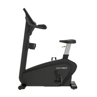
Perform Pro B6i - Exercise bike Flow Fitness - Free user manual and instructions
Find the device manual for free Perform Pro B6i Flow Fitness in PDF.


User questions about Perform Pro B6i Flow Fitness
0 question about this device. Answer the ones you know or ask your own.
Ask a new question about this device
Download the instructions for your Exercise bike in PDF format for free! Find your manual Perform Pro B6i - Flow Fitness and take your electronic device back in hand. On this page are published all the documents necessary for the use of your device. Perform Pro B6i by Flow Fitness.
USER MANUAL Perform Pro B6i Flow Fitness
natural_image
Technical line drawing of a stationary exercise machine (no text or symbols)Base frame
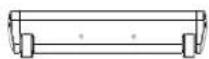
Front stabilizer
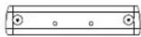
Rear stabilizer

Console cover
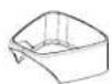
Base cover

Handlebar frame

Handlebar cover
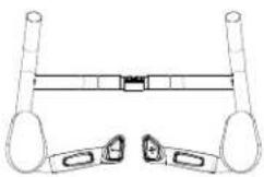
Handlebar set

Cup holder
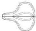
Seat cushion
| NO. Description | Quantity |
| 66 Base frame 1 | |
| 104 Front stabilizer 1 | |
| 68 Rear stabilizer 1 | |
| 122 Console cover 1 | |
| 48 Base cover 1 |
| NO. Description | Quantity |
| 1 Handlebar frame 1 | |
| 6 Handlebar set 1 | |
| 2 Handlebar cover 1 | |
| 4 Cup holder 1 | |
| 22 Seat cushion 1 |
All the necessary tools for assembly are included in the frame packing box:
- 5mm Allen Wrench (1)
- 8mm Allen Wrench (1)
- 6mm Allen Wrench (1)
- Open Spanner (1)
Ensure that all tools are available and prepared before beginning the assembly process.
Preparation Before Assembly:
- Open the packing box and carefully remove all parts.
- Lay the main frame flat on the ground.
- Check that all components listed in the parts list are present and complete.
Safety Tip:
When lifting the frame out of the box, it is recommended that three or more people assist in lifting and assembling the machine to avoid accidents.
STEP 1
- Open the 1# screw Bag: Take out all required screws from the 1# screw bag.
- Attach the front stabilizer:
- Use a 5mm Allen wrench to tighten the front stabilizer (Part 104) to the base frame (Part 66).
| NO. | Description | Quantity |
| 98 | M10 x 20 Hexagon socket button head screws | 2 |
| 100 | M10 x 20 Hexagon socket countersunk head screws | 2 |
| 101 | Φ11 Φ18 t0.8 Spring washer | 2 |
| 99 | Φ10.2 Φ15.4 t3.0 Spring washer | 2 |
Refer to the diagram for accurate placement and installation.
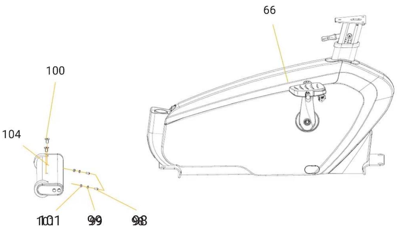
text_image
100 104 1001 99 98 66STEP 2
- Open the 2# screw bag: Take out all required screws from the 2# screw bag.
-
Attach the rear stabilizer:
-
Use an M6 inner Allen wrench to secure the rear stabilizer (Part 68) to the base frame (Part 66).
- Ensure the screws are tightened securely.
| NO. | Description | Quantity |
| 98 | M10 x 20 Hexagon socket button head screws | 2 |
| 100 | M10 x 20 Hexagon socket countersunk head screws | 2 |
| 101 | Φ11 Φ18 t0.8 Spring washer | 2 |
| 99 | Φ10.2 Φ15.4 t3.0 Spring washer | 2 |
Refer to the diagram provided for proper placement and assembly instructions.
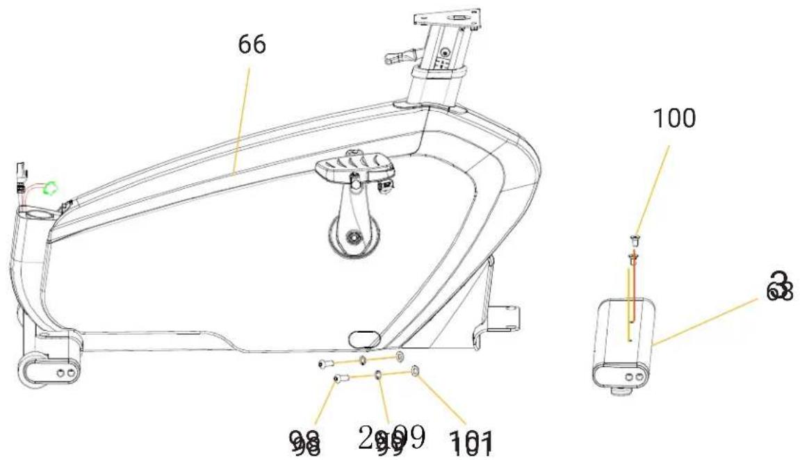
text_image
66 100 98 2009 101 38STEP 3
- Open the 3# screw Bag: Take out all required screws from the 3# screw bag.
- Remove the covers:
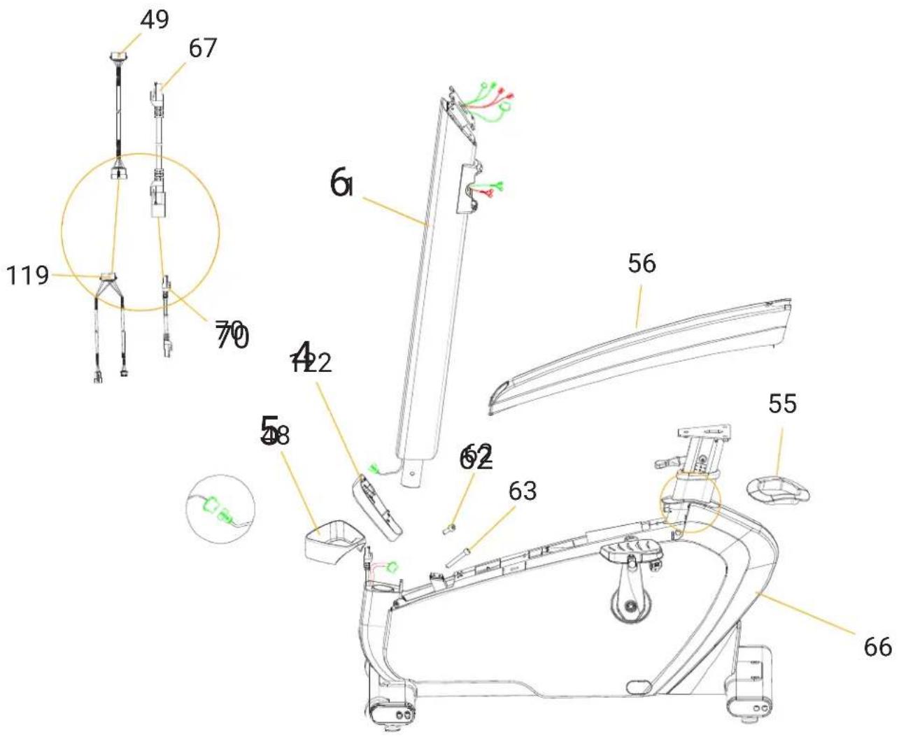
- Remove the seat tube front cover (Part 55) and then the protection cover (Part 56) from the frame.
- Install the console cover:
- Slide the console cover (Part 122) into the cluster gauge from bottom to top.
- Install the base cover:
- Slide the base cover (Part 48) into the cluster gauge from bottom to top, and connect it to the handlebar frame (Part 1).
-
Connect the signal wires:
-
Connect the upper signal wire (Part 49) to the lower signal wire (Part 119).
-
Connect the upper Internet wire (Part 67) to the lower Internet wire (Part 70).
-
Attach the handlebar frame:
-
Place the handlebar frame (Part 1) into the base frame (Part 66).
-
Use a allen wrench to securely tighten the connection.
-
Reinstall the protection cover:
- Reassemble the protection cover (Part 56) back onto the main frame.
- Reinstall the seat tube front cover:
- Place the seat tube front cover (Part 55) back onto the side cover.
- Install the final base cover:
- Finally, place the base cover (Part 48) into the cluster gauge.
| NO. Description Quantity | |
| 62 M10 x 20 Hexagon socket head cap screws 1 | |
| 63 M10 x 65 Hexagon socket head cap screws 1 |
Caution:
- Insert the allen wrench:
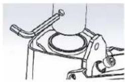
- Before attaching the handlebar frame to the base frame, insert the allen wrench into the hole of the handlebar frame. This will prevent the handlebar frame from hitting the bottom part during the assembly process.
-
Connect the signal wires:
-
After securing the handlebar frame, connect the upper and lower signal wires.
- Remove the wrench and tighten the screws:
- Once the wires are connected, remove the allen wrench, and use it to fully tighten the screws, securing the handlebar frame to the base frame.
text_image
49 67 119 70 6 42 58 62 63 55 56 66Caution: Before connecting the handlebar frame to the base frame, insert the Allen wrench into the designated hole on the handlebar frame. This will prevent the handlebar frame from making contact with the lower section. Next, connect the signal wires, remove the Allen wrench, and securely tighten the screw using the Allen wrench.
natural_image
Mechanical assembly diagram showing a cylindrical component mounted on a base with a flanged handle (no text or symbols visible)STEP 4
- Open the 4# screw Bag: Take out all required screws from the 4# screw bag.
-
Connect the wires:
-
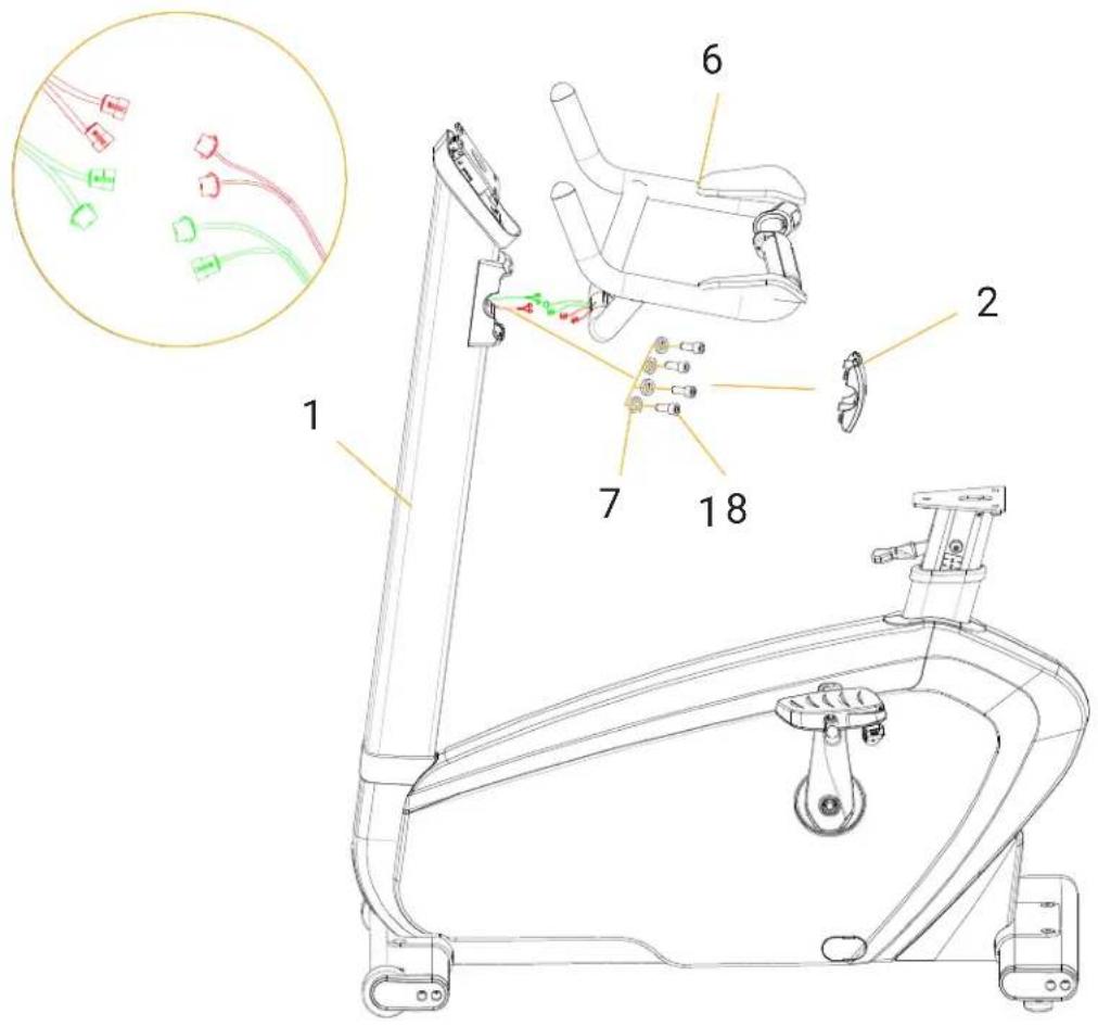
Connect the hand pulse connection wire with the middle section set wire.
-
Connect the resistance quick button wire with the middle section set wire.
-
Attach the handlebar set:
-
Place the handlebar set (Part 6) on the handlebar frame (Part 1).
-
Use an Allen wrench and the hardware provided to securely tighten the connection.
-
Install the cover:
- Attach the handlebar cover (Part 2) to the handle bar, ensuring that it fits securely.
| NO. | Description | Quantity |
| 8 | M8 x 20 Hexagon socket button head screws | 4 |
| 7 | Φ9 Φ16 t1.6 Flat washers | 4 |
Ensure all components are tightly fastened and that the connections are secure for proper functionality.
text_image
Technical diagram of a stationary exercise machine with numbered components and an inset showing wiring details.STEP 5
1. Remove console hardware:
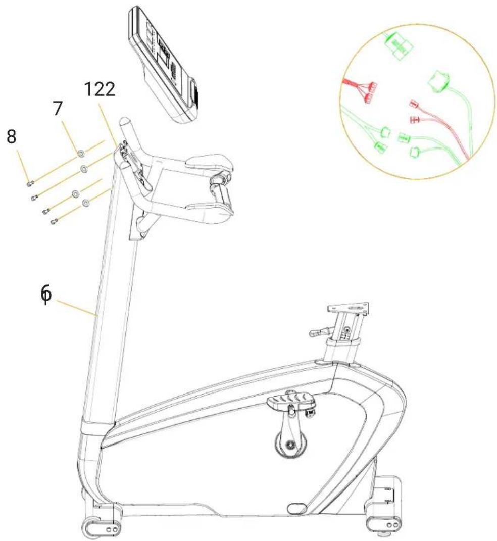
- Take out the console hardware and remove the four M8 screws from the console.
2. Connect the wires:
- Connect all upper console wires to the middle wire section, including the signal wire, hand pulse wire, and resistance wire.
3. Lock the console:
- Attach the console to the handle bar and securely tighten it using the provided hardware and an Allen wrench.
4. Install the console cover:
- Finally, connect and attach the console cover (Part 122) to complete the assembly.
| NO. | Description | Quantity |
| 8 | M8 x 20 Hexagon socket button head screws | 4 |
| 7 | Φ9 Φ16 t1.6 Flat washers | 4 |
Ensure all connections are secure and properly fastened before proceeding.
text_image
122 7 8 6STEP 6
- Open the 6# screw Bag: Take out all required screws from the 6# screw bag.
- Insert the cup Holder:
- Insert the cup holder (Part 4) into the handlebar frame (Part 1).
- Tighten with screwdriver:
- Use a crosshead screwdriver to secure the cup holder with the M4 x 12 screw provided. Ensure the cup holder is tightly secured and positioned correctly.
| NO. | Description | Quantity |
| 3 | Cross recessed pan head screw M4 x 12 | 1 |
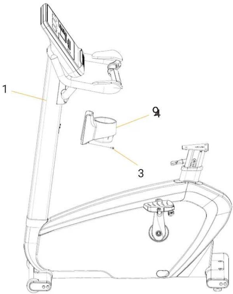
text_image
1 2 3 4STEP 7
1. Gather seat cushion accessories:
- Collect all the necessary accessories for the seat cushion.
2. Attach the seat cushion:
- Use an open spanner to securely fasten the seat cushion (Part 22) to the seat set.
Ensure the seat cushion is properly aligned and securely tightened for safe and comfortable use.
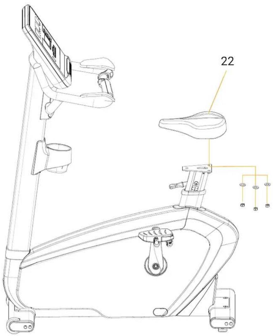
text_image
22Note: Most screws are pre-assembled.
Opmerking: De meeste schroeven zijn voor gemonteerd.
Hinweis: Die meisten Schrauben sind vormontiert.
Note: La plupart des vis sont pré-assemblées.
MANUAL (ENGLISH) 12-21
HANDLEIDING (NEDERLANDS) 22-31
Copyright © Flow Fitness
All rights reserved. Nothing in this instruction manual may be used or reproduced in any form or way without the express written permission of Flow Fitness.
2. INTRODUCTION....14
3. FITNESS....16
What is Fitness.... 16
Training by heart rate.... 16
Determining Your Training Goal 16
Warming up and cooling down 17
Training schedule.... 18
4. USE....19
Storage, moving and usage.... 19
5. PRODUCT INFORMATION ...... 20
Maintenance.... 20
Troubleshooting....20
6. WARRANTY 21
Warranty 21
HEALTH
IMPORTANT:
Read this instruction manual first and follow the instructions carefully before using the product.
- Consult an expert to determine the training level that is most suitable for you.
- If you experience any dizziness, nausea or any other physical discomfort while training, cease the training immediately and consult a physician.
- Watch your heart beat during the training and immediately stop training when values are inconsistent.
- We advise you to do warming up and cooling down exercises during five to ten minutes before and after use of the product. This way your heart rate can increase and decrease gradually and you can prevent painful muscles.
SAFETY
- Only use this product as described in this instruction manual.
- Before using this product check that the product functions as it should. In case of malfunction or a defect stop training immediately and contact your dealer.
- Do not use the product when there is a malfunction.
- The product has to be positioned on a flat surface.
- The product can only be used by one person at the same time.
- The product can be used by persons weighing up to 200 kg.
- Always make sure that there is at least one meter of free space in all directions around the product when you are training.
- Don't stick any objects in any opening of the product.
- Keep children and pets away from the product.
- Handicapped persons should get consent from a medical expert and follow their directions for training with the product
- Do not place hands or feet under the product.
- Never hold your breath during a training session. Your breathing should be at a normal interval depending on the intensity of the training.
- Start your training schedule slowly and build it up gradually.
- Always wear appropriate clothing during training. Don't wear anything that's too loose and can get caught between moving parts of the equipment.
- When moving the equipment, always use the appropriate lifting techniques to prevent back injury.
- Check screws and bolts regularly and fasten them if they are loose.
- The owner of the product is responsible for all users to be aware of the warnings and instructions as mentioned in this instruction manual.
- This product is intended for use in a clean and dry environment. Storage in cold and / or moist areas could lead to problems with the product.
WARNING
Have your physical condition checked by a licensed physician before you start training. This is particularly important for persons over 35 years old or persons who have any problems with their health. Read all instructions before using the equipment. Flow Fitness is not responsible for any personal injury or damage to property caused by the use of this equipment.
SPECIFICATIONS
| Size (cm) 112.3 x 67.5 x 150.6 Crank distance (cm) 18 | ||
| Power 400 W Resistance range L1 - L40 | ||
| Category SA User's weight (kg) 200 | ||
| Temperature 0 ~ 33 °C Net (kg) 88 | ||
| Seat/back pad PU foam Gross (kg) 98 | ||
| Console display Speed / Time / Distance / Power / Heart Rate / Calorie | ||
TECHNOLOGY
EMS (Electromagnetic Resistance)
Self-generator
40 Resistance levels
EXTRA
Comfortable TPR Handle
Anti-Slip Pedals
Self-Generating Motor
Quick Resistance Buttons
Heart Rate Monitoring Function
Ergonomic Design
This manual contains all the information necessary for using and operating this upright bike. Additionally, the manual includes tips and advice on how to train effectively.
We recommend that you carefully read this manual before using the Perform Pro B6i to ensure that the product is used optimally and safely.
Flow Fitness wishes you great success and enjoyment in your training.
WHAT IS FITNESS
What is fitness? Generally it can be described as a fitness exercise that causes your heart to pump more oxygen to your muscles via the blood from your lungs. The harder the workout, the more fuel (oxygen) the muscles require to achieve this rate of oxygen. The heart has to pump harder to get the oxygenated blood into the muscles. If you have good stamina, your heart pumps more blood with each heartbeat. The heart will not have to beat that often to transport the necessary oxygen into your muscles. Your resting heart rate and heart rate during exercise will reduce.
TRAINING BY HEART RATE
While training it is important to monitor your heart rate. The heart rate is essential for the result of your training. Your best training heart rate depends firstly on your age. Your maximum heart beat can be determined by this. Secondly, the most effective heart rate depends on your training goals. If your training goal is to lose weight, then the most effective training is at 60% of your maximum heart rate. If your training goal is to improve your stamina, then you should train at 85% of your maximum heart rate. The body stores energy in two forms: carbohydrates and fat. When we exercise we use a combination of these two energy supplies. If the training intensity is at a high level the body will mostly choose the energy that burns fast: carbohydrates. Since there is a limited supply of these carbohydrates you can't continue this for a long period of time. When training at a low intensity the body will mostly choose to use a long lasting source of energy: fat. Since this is stored in large quantities in the body, you can continue this kind of training for a longer time.
DETERMINING YOUR TRAININGS GOAL
Below you will find a schedule allowing you to calculate the best heart rate for your training. In this schedule each age category has a range that your heart rate should be in during your training. The middle column has the values you should try to maintain if you want to lose weight. If you want to improve your stamina you should try to maintain the rates in the right column. For each individual the best way to start training is different. If you have not exercised in some time or are overweight, you should start your training schedule slowly and gradually increase the level of activity.
| Age | Losing Weight(beats per minute)60% | Improving stamina(beats per minute)85% |
| 20 - 24 120 - 118 170 - 167 | ||
| 25 - 29 117 - 115 166 - 163 | ||
| 30 - 34 114 - 112 162 - 158 | ||
| 35 - 39 111 - 109 157 - 154 | ||
| 40 - 44 108 - 106 153 - 150 | ||
| 45 - 49 105 - 103 149 - 145 | ||
| 50 - 54 102 - 100 144 - 141 | ||
| 55 - 59 99 - 97 140 - 137 | ||
| 60 and older 96 - 94 136 - 133 |
In the last chapter of this instruction manual you will find several different training schedules (chapter 5, general information). You can use these schedules to reach your training goals. The schedules are divided in two phases. The first phase can be used for beginners or persons who start training after a long period of inactivity. During this phase the level of intensity is built up gradually. After six weeks the second phase begins. You can then choose a training schedule to lose weight or improve your stamina.
WARMING UP & COOLING DOWN
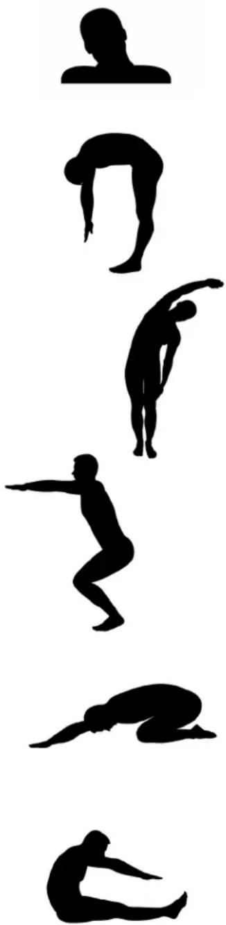
A good training schedule starts with a good warming up and ends with a cooling down of the muscles. This will prevent painful muscles and injury. Below you will find some suitable exercises.
natural_image
Silhouettes of various human postures in various poses, arranged vertically (no text or symbols)Head Roll
Tilt your head to the right. Hold this for one second, so that you feel a little pull in the muscles on the left side of your neck. Do the same for the other side, front and back. Repeat two or three times.
Toe Touch
Slowly bend forward with your back and arms relaxed. Bend as far as you can and hold the position for ten seconds. Repeat this two or three times.
Side Stretch
Extend both your arms up in the air and reach as high as you can with your right arm. Lean a bit to the left so that the muscles in the right side of your torso are stretched. Hold this position for one second. Relax and make the same motion on the other side of your body. Repeat this three or four times.
Knee bend
Set your feet shoulder-width apart and your stretched your hands out. Lower yourself no more than 10cm by bending your knees. Come back up again and repeat several times.
Lower back stretch
Begin on all fours. Stretch your arms out in front of you, allowing your face to lower to a position near the floor. Gently sit back. Rest your glutes just above your heels. Ease back and feel the gentle stretch in your lower back.
Hamstring Stretch
Sit down on the floor with your right leg extended in front of you and place the sole of your left foot on the inside of your right upper leg. Bend forward in the direction of your right foot and hold this position for ten seconds. Relax and then do the same with your other leg. Repeat two or three times.
TRAINING SCHEDULE
Schedule week 1 and 2
Train at 60% of your maximum heart rate. Max. 3 times a week.
Warming up 5 - 10 minutes.
Train 4 minutes.
Rest 1 minute.
Train 2 minutes.
Calmly train 1 minute.
Cooling down 5 minutes.
Schedule week 3 and 4
Train at 60% of your maximum heart rate. Max. 4 times a week.
Warming up 5 - 10 minutes.
Train 5 minutes.
Rest 1 minute.
Train 3 minutes.
Calmly train 1 minute.
Cooling down 5 minutes.
Schedule week 5 and 6
Train at 60% of your maximum heart rate. Max. 5 times a week.
Warming up 5 - 10 minutes.
Train 6 minutes.
Rest 1 minute.
Train 4 minutes.
Calmly train 3 minutes.
Cooling down 5 minutes.
After completing the introduction training schedule for six weeks, you can choose the follow-up training schedule that is best suited to your needs. You can choose a schedule that will maximize your weight loss, or one that will improve your stamina. Both training schedules are on the next pages.
Training schedule to improve stamina
follow-up to introduction training schedule)
Schedule week 7 and 8
Train at 90% of your maximum heart rate. Max. 6 times a week.
Warming up 5 - 10 minutes.
Train 7 minutes.
Rest 1 minute.
Train 5 minutes.
Calmly train 1 minute.
Cooling down 5 minutes.
Schedule week 9 and beyond
Train at 90% of your maximum heart rate. Max. 6 times a week.
Warming up 5 - 10 minutes.
Train 10 minutes.
Rest 1 minute.
Train 10 minutes.
Repeat training 2 or 3 times.
Calmly train 1 minute.
Cooling down 5 minutes.
Training schedule to lose weight
(follow-up to introduction training schedule)
Schedule week 7 and 8
Train at 60% of your maximum heart rate. Max. 6 times a week.
Warming up 5 - 10 minutes.
Train 7 minutes.
Rest 1 minute.
Train 5 minutes.
Calmly train 1 minute.
Cooling down 5 minutes.
Schedule week 9 and beyond
Train at 60% of your maximum heart rate. Max. 6 times a week.
Warming up 5 - 10 minutes.
Train 10 minutes.
Rest 1 minute.
Train 10 minutes.
Repeat training 2 or 3 times.
Calmly train 1 minute.
Cooling down 5 minutes.
STORAGE, MOVING AND USAGE
Moving the Equipment:
- Ensure the equipment has come to a complete stop. Stand at the rear of the equipment and use both hands to lift the back end.
- Carefully push the equipment forward to the desired location.
Seat Position Adjustment
To ensure a comfortable workout, adjust the seat cushion to your ideal position according to your posture.
Seat Adjustment Procedure:
- Stand beside the upright bike to adjust the seat height as needed.
- To lower the seat, pull the lever and press the seat downward.
- To elevate the seat, pull the lever and allow the seat to rise.
MAINTENANCE
Regular Inspection and Fastening
Flow Fitness recommends checking and tightening all nuts, bolts, and pivot points every six weeks. Use the tool provided with the product for this task.
Cleaning
After each training session, clean the metal and plastic components using standard cleaning products. Ensure all parts are completely dry before using the equipment again.
Note: Do not use corrosive cleaning agents, as they may damage the equipment.
Usage Environment
To minimize wear and extend the product's lifespan, the elliptical should only be used indoors in a dry environment.
TROUBLESHOOTING
Problem During a training the upright bike makes beeping or scratching noises.
Solution: Beeping or scratching noise are mostly caused by the plastic cover hitting or scratching the metal frame. The solution to this problem is to spray this components with PTFE spray or Flow Fitness Treadmill Lotion. PTFE is available in hardware stores.
Problem The upright bike does not turn on.
Solution: Ensure all connections are securely in place. As the machine is self-powered, the user must begin exercising to activate the display and generate power for the equipment.
In case your problem is not resolved or not described, consult the Flow Fitness reseller where you purchased this product.
WARRANTY
The warranty is provided by the Flow Fitness distributor of your country and the reseller where you have purchased your product. Please check https://www.flowfitness.com/en/dealers/ for contact information.
1. BELANGRIJKE INFORMATIE......23
Gezondheid 23
Veiligheid 23
2. INTRODUCTIE....24
3. FITNESS....26
Wat is Fitness.... 26
5. PRODUCT INFORMATIE ....30
Onderhoud.... 30
Probleemoplossen....30
6. GARANTIE....31
WARMING UP EN COOLING DOWN
natural_image
Silhouettes of various human postures in various poses, arranged vertically (no text or symbols)Head Roll
Cooling down 5 minutes.
Trainingsschema week 3 en 4
Cooling down 5 minutes.
Trainingsschema week 5 en 6
Cooling down 5 minutes.
Cooling down 5 minutes.
Trainingsschema week 9 en verder
Cooling down 5 minutes.
Cooling down 5 minutes.
Trainingsschema week 9 en verder
Cooling down 5 minutes.
https://www.flowfitness.com/nl/registreer-uw-product/
natural_image
Silhouettes of various human postures in various poses, arranged vertically (no text or symbols)Kopfrollen
10 minuten Training.
1 Minute Pause.
10 minuten Training.
10 minuten Training.
1 Minute Pause.
10 minuten Training.
To minimize wear and extend the lifespan of the device, the elliptical trainer should only be used indoors and in a dry environment.
PROBLEMLÖSUNG
2. INTRODUCTION....44
3. FITNESS 46
natural_image
Silhouettes of various human postures in various poses, including stretching, stretching, and kneeling (no text or symbols)Rotation de la tête
CONDITIONS DE GARANTIE
text_image
Technical schematic diagram of a mechanical device with numbered components and exploded views| NO | Description Quantity | |
| 1 | Handle bar frame 1 | |
| 2 | Handle bar cover 1 | |
| 3 | Cross recessed pan head screw 20 | |
| 4 | Cup holder 1 | |
| 5 | Electrophoresis cup holder fixing piece 1 | |
| 6 | Handle bar set 1 | |
| 7 | 9 16 t1.6 Flat washers 4 | |
| 8 | M8 x 20 Hexagon socket button head screws 6 | |
| 9 | Handrail tube lower cover baffle 1 | |
| 10 | Panel sticker (plus) 1 | |
| 11 | Membrane key (resistance adjustment) 2 | |
| 12 | Heartbeat grip a 2 | |
| 13 | Cross recessed pan head topping screw 8 | |
| 14 | Membrane key adapter 2 | |
| 15 | Heartbeat grip B 2 | |
| 16 | Panel sticker (minus) 1 | |
| 17 | Left trim cover of rear foot tube 1 | |
| 18 | Rear foot tube right trim cover 1 | |
| 19 | Hardware screw package 1 | |
| 20 | Hardware screw package 1 | |
| 21 | Cross recessed pan head screw 4 | |
| 22 | Seat cushion 1 | |
| 23 | Hexagon socket flat round head screw 1 | |
| 24 | Light spring washer 1 | |
| 25 | Flat washer 3 | |
| 26 | Adjusting handle (plastic impregnation) 1 | |
| 27 | Pneumatic rod regulating handle plastic 1 | |
| 28 | Cap nut 1 | |
| 29 | Hexagon socket flat round head screw 1 | |
| 30 | Spring 1 | |
| 31 | Cap nut 1 | |
| 32 | Pipe bolder welding (aluminum) 1 | |
| 33 | Pneumatic rod fixed plastic 1 | |
| 34 | Pneumatic rod support plate (electrophoresis) 1 | |
| 35 | Pneumatic rod 1 | |
| 36 | Hexagon socket flat round head screw 1 | |
| 37 | Cross recessed pan head self topping and self 4 | |
| 38 | Shaft (PANTONE Black 6C) 2 | |
| 39 | Seat tube lower bushing 1 | |
| 40 | Cross recessed countersunk head screw 2 | |
| 41 | Cross recessed pan head topping screw 1 | |
| 42 | Bushing on seat tube 1 | |
| 43 | Cross recessed pan head topping screw 16 | |
| 44 | C-clip (clip nut) 8 | |
| 45 | Side cover connecting piece (electrophoresis) 4 | |
| 46 | Velcro 1 |
| NO | Description Quantity | |
| 47 Left side cover | 1 | |
| 48 Base cover | 1 | |
| 49 Communication line Instrument rod section | 1 | |
| 50 Cover connection pin | 5 | |
| 51 Left screw cover | 1 | |
| 52 Cross recessed countersunk head screw | 4 | |
| 53 Crank left (point baking) | 1 | |
| 54 Crank left (point baking) | 1 | |
| 55 Upper cover of base pipe | 1 | |
| 56 Service cover | 1 | |
| 57 Controller | 1 | |
| 58 Battery | 1 | |
| 59 Maintenance cover | 1 | |
| 60 Cross recessed countersunk head tapping screws | 4 | |
| 61 Velcro | 1 | |
| 62 M10 x 20 Hexagon socket head cap screws | 1 | |
| 63 M10 x 65 Hexagon socket head cap screws | 1 | |
| 64 Seat tube sticker | 2 | |
| 65 DC power supply fixing board | 1 | |
| 66 Base frame | 1 | |
| 67 B6i upper network cable | 1 | |
| 68 Rear stabilizer | 1 | |
| 69 Adjust the foot pad | 2 | |
| 70 B6i lower network cable | 1 | |
| 71 Crank shaft | 1 | |
| 72 Bearing | 2 | |
| 73 Flat washer | 1 | |
| 74 Flat key | 1 | |
| 75 Large pulley | 1 | |
| 76 Hexagon nut | 1 | |
| 77 Multi groove belt | 1 | |
| 78 Cover connection pin 2 | 5 | |
| 79 Screw cover right 1 | ||
| 80 Right side cover | 1 | |
| 81 Crank right (paint baking) 1 | ||
| 82 Crank flange nut | 2 | |
| 83 Crank trim cover | 2 | |
| 84 Hexagon socket head cap screw | 4 | |
| 85 Flat washer | 4 | |
| 86 Spring washer | 4 | |
| 87 Flywheel generator | 1 | |
| 88 Spring | 1 | |
| 89 Pressure wheel mounting plate | 1 | |
| 90 Pressure wheel mounting shaft | 1 | |
| 91 Pressure wheel | 1 | |
| 92 Bearing | 1 |
| NO Description Quantity | |
| 93 For C-type snap ring hole 2 | |
| 94 Large washer 2 | |
| 95 Cross recessed pan head screw 2 | |
| 96 Pressure wheel fixing plate bushing 3 | |
| 97 Cross recessed pan head screw 3 | |
| 98 M10 x 20 Hexagon socket button head screws 4 | |
| 99 Φ10.2 Φ15.4 t3.0 Spring washer 4 | |
| 100 M10 x 20 Hexagon socket countersunk head screws | 4 |
| 101 Φ11 Φ18 t0.8 Spring washer 4 | |
| 102 Front foot tube end plug le 2 | |
| 103 Front roller 2 | |
| 104 Front stabilizer 1 | |
| 105 Wave type elastic washer 2 | |
| 106 Extra large washer 2 | |
| 107 Front foot tube end plug right 2 | |
| 108 DC12V input line 1 | |
| 109 Resistance shortcut key connector (-) | 1 |
| 110 Resistance shortcut key connector (+) | 1 |
| 111 Holding heart rate line (grip section) | 2 |
| 112 Battery connecting wire 1 | |
| 113 Hardware screw package 1 | |
| 114 Generator output line 1 | |
| 115 Magnetic control line 1 | |
| 116 Resistance shortcut cable 1 | |
| 117 Hand held heart sensor cable 1 | |
| 118 Outer circlip (for shaft) 1 | |
| 119 Communication line_Lower segment 1 | |
| 120 network interface 1 | |
| 121 Left clip of instrument 1 | |
| 122 Console cover 1 | |
| 123 Right clip of instrument 1 | |
| 124 Cable tie 8 | |
| 125 Cable tie 5 | |
| 126 Cable tie 2 | |
| 127 5mm inner hexagon wrench 1 | |
| 128 6mm inner hexagon wrench 1 | |
| 129 8mm inner hexagon wrench 1 |