ECVW3062SS - Basket ELECTROLUX - Free user manual and instructions
Find the device manual for free ECVW3062SS ELECTROLUX in PDF.

User questions about ECVW3062SS ELECTROLUX
0 question about this device. Answer the ones you know or ask your own.
Ask a new question about this device
Download the instructions for your Basket in PDF format for free! Find your manual ECVW3062SS - ELECTROLUX and take your electronic device back in hand. On this page are published all the documents necessary for the use of your device. ECVW3062SS by ELECTROLUX.
USER MANUAL ECVW3062SS ELECTROLUX
natural_image
Three white line icons: open book, crossed wrench and screwdriver, and shopping cart (no text or symbols)electrolux.com\register

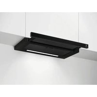
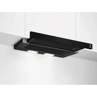
Electrolux
Welcome to Electrolux! Thank you for choosing our appliance.

For Customer Care support and webshop visit:
www.electrolux.com/support/

For extended version of User Manual visit:
www.electrolux.com/manuals/
Subject to change without notice.
CONTENTS
- SAFETY INSTRUCTIONS----2--
- ELECTRICAL REQUIREMENTS----5----
- PARTS SUPPLIED----6-
- OPTIONAL ACCESSORIES----6-
- INSTALLING THE HOOD 7
- OPERATION----12-
- SPECIAL FUNCTION----12-
- CLEANING AND MAINTENANCE----13
- TECHNICAL DATA 14
10.TROUBLE SHOOTING----14
11.ENVIRONMENTAL PROTECTION----14
12.WARRANTY INFORMATION----15
SAFETY INSTRUCTIONS
Do not attempt to install or operate this appliance until you have read the safety instructions in this manual. Safety items throughout this manual are labelled with a Danger, Warning, or Caution based on the risk type.
DEFINITIONS
This is the safety alert symbol. It is used to alert you to potential personal injury hazards. Obey all safety messages that follow this symbol to avoid possible injury or death.
DANGER:
DANGER indicates an imminently hazardous situation which, if not avoided, will result in death or serious injury.
WARNING:
DANGER indicates an imminently hazardous situation which, if not avoided, will result in death or serious injury.
2 ENGLISH

CAUTION :
CAUTION indicates a potentially hazardous situation which, if not avoided, could result in minor or moderate injury.
CHILD SAFETY
Packing materials:
- Packing cartons covered with rugs, bedspreads, plastic sheets, or stretch wrap may become airtight chambers and can quickly cause suffocation.
- Removetheprotectivefilm coveringtheappliance before putting it into operation.
- Destroy or recycle the appliance's carton, plastic bags, and any other exterior wrapping material immediately after the product is unpacked. Children should never play with these items. Danger of suffocation!

IMPORTANT
CAREFULLY BEFORE INSTALLATION AND USE.
INSTALLATION MUST COMPLY WITH ALL LOCAL CODES.
IMPORTANT: Save these instructions for the Local Electrical Inspector's use.
INSTALLER: Please leave these instructions with this appliance for the owner.
OWNER: Please retain these instructions for future reference.

DANGER:
Always switch off the electricity supply at the mains during installation and maintenance.

WARNING:
To reduce the risk of fire, electric shock, or injury to persons, observe the following:
• FOR RESIDENTIAL USE ONLY
- Use this appliance only in the manner intended by the manufacturer. If you have questions, contact the manufacturer.
Installation work and electrical wiring must be done by qualified person(s) in accordance With all applicable codes & standards, including fire-rated construction.
- Sufficient air is needed for proper combustion and exhausting of gases through the flue (chimney) of fuel burning equipment to prevent back-drafting. Follow the heating equipment manufacturers guideline and safety standards such as those published by the National Fire Protection Association (NFPA), the American Society for Heating, Refrigeration and Air Conditioning Engineers (ASHRAE), and the local code authorities.
- When cutting or drilling into wall or ceiling, do not damage electrical wiring and other hidden utilities (e.g. gas pipes). Ducted systems must always be vented to the outdoors. always be vented to the outdoors.

WARNING:
Before servicing or cleaning the unit, switch power off at service panel and lock service panel disconnecting means to prevent power from being switched on accidentally.
When the service disconnecting means cannot be locked, securely fasten a prominent warning device, such as a tag, to the service panel.

CAUTION:
For general ventilating use only. DO NOT use to exhaust hazardous or explosive materials or vapors.

CAUTION:
To reduce risk of fire and to properly exhaust air, be sure to duct air outside - do not vent exhaust air into spaces within walls, ceilings, attics, crawl spaces, or garages.

WARNING:
To reduce the risk of fire, use only metal duct work. Install this hood in accordance with all requirements specified.

WARNING:
To reduce the risk of fire or electric shock, do not use this hood with any external solid state speed control device.

WARNING:
To reduce the risk of a cooker top grease fire:
- Never leave surface units unattended at high settings. Boilovers cause smoking and greasy spillovers that may ignite. Heat oils slowly on low or medium settings.
• Always turn hood on when cooking over high heat.

WARNING:
- Do not use the range hood without the grease filters, or if the filters are excessively greasy.
- Use proper pan size. Always use cookware appropriate for the size of the surface element.

WARNING:
To reduce the risk of injury to persons, in the event of a cooker top grease fire, observe the following:
- Smother flames with a close-fitting lid, cookie sheet, or other metal tray, then turn off the gas burner or the electric element. Be careful to prevent burns. If the flames do not go out immediately, evacuate and call the fire department.
- Do not use water, including wet dishcloths or towels - a violent steam explosion will result.
- Use an extinguisher only if:
- You know you have a class ABC extinguisher, and you already know how to operate it.
- The fire is small and contained in the area where it started.
• The fire department is being called. - You can fight the fire with your back to an exit.

CAUTION:
Always leave safety grills and filters in place.
ELECTRICAL REQUIREMENTS

IMPORTANT
Observe all governing codes and ordinances.

CAUTION:
To Reduce The Risk Of Fire And Electric Shock, Install This Rangehood Only With Integral Blowers Manufactured by Chinabest Home Appliance Co., Ltd, Model CTH03-128D.
It is the customer's responsibility:
• to contact a qualified electrical installer.
• to assure that the electrical installation is adequate and in conformance with National Electrical Code, ANSI/NFPA 70 - latest edition*, or CSA Standards C22.1-94, Canadian Electrical Code, Part 1 and C22.2 No.0-M91-latest edition**
and all local codes and ordinances.
If codes permit and a separate ground wire is
• used, it is recommended that a qualified electrician determines that the ground path is adequate.
• Do not ground to a gas pipe.
- Check with a qualified electrician if you are not sure range hood is properly grounded.
- Do not have a fuse in the neutral or ground circuit.

IMPORTANT
Save installation instructions for electrical inspector's use.
The range hood must be connected with copper wire only.
The range hood should be connected directly to the fused disconnect (or circuit breaker) box through metal electrical conduit.
Wire sizes must conform to the requirements of the National Electrical Code ANSI/NFPA 70 - latest edition", or CSA Standards C22.1-94, Canadian Electrical Code Part 1 and C22.2 No.0-M91 - latest edition** and all local codes and ordinances.
A U.L.- or C.S.A.-listed conduit connector must be provided at each end of the power supply conduit (at the range hood and at the junction box).
Copies of the standards listed may be obtained from:
* National Fire Protection Association Battery march Park Quincy, Massachusetts 02269
** CSA International 8501 East Pleasant Valley Road Cleveland, Ohio 44131-5575
Power requirement:
120V-, 60Hz, 15 or 20A branch circuit.
PARTS SUPPLIED
| No. | Part | Qty. | |
| 1. |  | Range hood | 1 |
| 2. |  | Upper chimney+Lower chimney | 2.1+2.2 |
| 3. |  | Aspiration plate | 1 |
| 4. |  | Upper bracket | 1 |
| 5. |  | Lower bracket | 1 |
| 6. |  | Mounting bracket | 1 |
| 7. |  | Side Sponge strip | 2 |
| 8. |  | Front Sponge strip | 1 |
| No. | Part | Qty. | |
| 9. |  | Anti-Vibration Pad | 2 |
| 10. |  | Wall Anchor | 9 |
| 11. |  | Long screw ST3.5x50 | 9 |
| 12. | [BW0A] | Short screw M4 8 | 2 |
| 13. |  | Wire Nut 3 | |
| 14. |  | Cross socket Head Screw M4 14 | 2 |
| 15. |  | Mounting Template | 1 |
OPTIONAL ACCESSORIES
| 1. |  | 8' extension chimneyElux PN:EHW08X62AS | 1 |
| 12' extension chimneyElux PN:EHW12X62AS | |||
| 14' extension chimneyElux PN:EHW14X62AS | |||
| 2. |   | Recirculation Kit with screwsElux PN: EHW62RKT | 1 |

IMPORTANT
We recommend that two people carry out the installation.

WARNING:
Turn off electrical power at service entrance before wiring.
Preparation
• Determine the exact location of the range hood.
- Plan the route for venting exhaust to the outdoors(fig.③)
- Plan the power connection prior to installation so that electrical wiring will not be visible afterwards.
• House wiring location: The junction box is located on the top right side of the hood.
- Wiring should enter the back wall at least 20" above the bottom of the hood at height install and be contained within the flue covers.
It is best if the wiring is located offset to the right of center to avoid interference with ducting(Fig. ①②).
Fig.①

flowchart
graph TD
    A["3-4/5"circle center to wall"] --> B["For ceiling ventducting"]
    B --> C["6-1/4"dia.hole"]
    C --> D["For wall Vent duct"]
    D --> E["Circle center at above the marked bottom pencil line."]
    E --> F["Horizontal straight pencil line"]
    F --> G["Installation height HorizontalLine"]
    style A fill:#f9f,stroke:#333
    style B fill:#ccf,stroke:#333
    style C fill:#cfc,stroke:#333
    style D fill:#fcc,stroke:#333
    style E fill:#ffc,stroke:#333
    style F fill:#fcc,stroke:#333
    style G fill:#fff,stroke:#333
- Use the shortest and straightest duct route possible.
• Any wall modifications needed (i.e. support structure, wiring, ducting) must be completed prior to installation of the range hood.
- Tools Required (not included):
→ Exhaust duct
Power drill
→ Screwdriver
→ Level
→ Cable detector
→ Measuring tape
- Foil backed tape
Fig.②

text_image
Ceiling height Installation height 30" Center line 36"Ducting installation guidelines
- For safety reasons when ducting outdoors (not using a recirculation kit), Ducting must vent directly outdoors (not into an attic, undemeath the house, into the garage or into any enclosed space).
- Keep duct runs as short and straight as possible.
- Duct fittings (elbows and transitions) reduce air flow efficiency.
- Back to back elbow and "S" turns give very poor delivery and are not recommended.
• Use a suitable 6" round duct. - Flex metal ducts are not recommended. Limit use to short lengths and do not crush when making comers.
Examples of possible ducting or air fig. recirculation
Fig.③

text_image
Roof pitch with flashing and cap Sidewall cap Recirculator Pipe Collar Pipe Collar Pipe Collar
IMPORTANT
- This range hood is very heavy. Adequate structure and support must be provided in all types of installations
Adding additional bracing is recommended and maybe required.
Installing range hood to the wall (Exhaust operation)
Install framing for hood support
- Using the dimensions or the template, mark the locations needed for support.
- Cut away enough drywall to expose 2 vertical studs at the holes location indicated by the template. Install horizontal supports between the wall studs at all mounting locations (fig.④).
Fig.④

text_image
8-1/2" min. opening for ductwork View From Rear Cleats Mounting Support Centerline of Installation Space
IMPORTANT
Framing must be capable of supporting 100 lbs
Step 1:
• Make sure that no cables or pipes will become damaged (e.g. electric, gas, water; test the areas in question with a cable detector).
- Before placing the supplied template, please mark the center line of the cooktop And measure up 30" from the cooktop.
- Using supplied mounting template(Item 15) mark and drill 9 holes in the wall. Drill the holes according to the measured distances from the diagram(fig.⑤)
- Upper/Lower/Mounting bracket (4,5,6)/Anti\~tilt fixing point: Insert 9 anchors into the 9 drilled holes.

text_image
Fig.⑤ Ceiling Long screw Anchor Long screw Anchor Long screw Anchor Long screw Anchor Drywall 30 in.Refer to Mounting Template(Item 15)
Step 2:
- Mount upper, lower and mounting brackets (4,5,6) on the wall. Secure with 7 sets of long screws (fig. ⑥).
Fig.⑥

natural_image
Pure electrical circuit lines without any symbolsIMPORTANT
Lower bracket is not required for 8 feet ceiling's installation.
Step3:
WARNING:
This range hood is very heavy. Two persons are needed to lift the hood onto the mounting bracket.
IMPORTANT
Before hooking the hood onto the wall please make sure the aspiration plate has been removed from the body to avoid it fall and injury to installer.
- Install the Anti-Vibration Pad (Item 9) to the rear of the hood body (fig⑦). Peel off the backing and stick the sponge strips (Item 7,8) to the front and sides of the upper fan housing as shown in (fig⑧).
- Carefully install the hood on the mounting bracket until it rests on the wall. Make sure to check that the hood is centered over the cook-top and between cabinets if applicable before moving to next step.
- Install mounting screws as shown in (fig ⑨) to prevent tilting and vibrations.
Fig.⑦

natural_image
Technical line drawing of a mechanical component with mounting base and cylindrical top (no text or symbols)Fig.⑧

text_image
5mm 10mm x 10mm
natural_image
Technical line drawing of a mechanical assembly with a suspended component (no text or symbols)• Install and secure the duct as shown in (fig 10). Assure that connections are airtight, observe all best practices, local codes, and regulations for hood exhaust venting.
Fig.⑩

natural_image
Line drawing of a hand placing a component into a column on a base, against a grid background (no text or symbols)Electrical connections

DANGER
Danger of electric shock! All connections should be made by a qualified electrician in accordance with all applicable codes and regulations.

IMPORTANT
Always switch off the electricity supply at the mains during installation, cleaning and maintenance.
Step 4:
- Loosen the 4 short screws from the junction box(fig.⑪).
Fig.⑪

natural_image
Technical line drawing of a mechanical assembly with a hand holding a tool, no visible text or symbols- Connect the incoming positive, neutral and ground cables to the respective terminals.(fig.⑫).
Fig.⑫

text_image
L (live) = Black N (neutral) = White ⊕ (ground) = Green- Mount the junction box onto the range hood using 4 short screws(fig.⑬).
Fig.⑬

natural_image
Technical line drawing of a mechanical assembly with a hand holding a tool and a rotating arrow indicating motion (no text or symbols)Step 5:
- Insert the upper chimney (Item 2.1) into the lower chimney (Item 2.2) from top to bottom (fig. ⑭).
- Mount lower chimney (Item 2.2) on the range hood (Item 1).
• Fit the lower chimney (Item 2.2) to the lower bracket (Item 5) using 2 screws (Item 14) by hand (fig. ⑮ then tighten the screws using screw driver (fig. ⑯).
Fig.⑭

natural_image
Simple line drawing of a two-tiered storage unit with a downward arrow indicating compression (no text or symbols)Fig.15

text_image
Diagram illustrating a mechanical or electrical system with a person inside a container and an inset showing a hand holding a device.Fig.⑯

natural_image
Diagram showing a hand holding a tool near a vertical structure, with an inset close-up of the handle (no text or symbols present)- Pull the upper chimney(2.1) to the upward position to match the screw hole of the upper bracket. Mount to the upper bracket(4) with 2 side screws 12 (fig.⑰).
Fig.17

natural_image
Simple line drawing of a box with an arrow indicating direction, no text or symbols present
CAUTION
Danger of injury. The chimney skirts may have some sharp edges.
Step 6:
Install the aspiration plate to the hood body.
- Fit the right bracket on the pre-metal plate to the right fixed hinge (fig. 18), then push the left hinge to the end to match the hole of the left bracket on the plate and release the hinge to lock them. (fig. 19).
Fig.⑱

natural_image
Simple line drawing of a mechanical lever system with an arrow indicating direction (no text or symbols)Fig.⑲

natural_image
Simple line drawing of a ladder leaning against an inclined plane, with an arrow indicating motion direction (no text or symbols)Exhaust operation
Makeup Air
- Local building codes may require the use of makeup air systems when using ventilation systems greater than specified CFM of air movement. The specified CFM varies from locale to locale. Consult your HVAC professional for specific requirements in your area.
- Recirculated air: Kitchen fumes are removed and after purification are fed back into the room through the upper ventilation openings. The purification takes place via metallic anti-grease filter. No wall breakthrough is required for recirculated air operation.
Installing range hood to the wall in recirculation mode
- For the operation of the range hood with recirculation recirculation kit# EHW62RKT is needed and can be purchased by calling 1-800-944-9044 (USA) or 1-800-265-8352 (Canada)
- Follow steps 1 to 4 from Installing range hood to the wall(Exhaust operation) chapter.
• To install the recirculation box, drill 2 additional holes in the wall. - Fix the recirculation box to the wall with 2 sets of long screws (Item 11) and wall plugs (Item 10) (fig.⑳).
- Attach the exhaust duct on the bottom of the recirculation box.
- Follow step 5 from Installing range hood to the wall(Exhaust operation) sub-chapter.
Fig.⑳

text_image
51/2"~111/2" Front View
text_image
Fig.⑳ Upper bracket Recirculation Box Wall Lower bracketSide View

natural_image
Technical line drawing of an open electrical enclosure with a circular component and internal components (no text or symbols)Reinstall the grease filter close aspiration plate.(fig.②1).
Install charcoal filter to each side of the blower motor by inserting the filters onto the "T" shaped stud and twisting to lock them into place.
OPERATION
Press one of the speed ¥1/¥2/¥3 button to turn the appliance on.
| Button | Function |
| 1 | Press button 1 to switch the appliance off. |
| Press button for low speed. | |
| Press button for medium speed. | |
| Press button for high speed. | |
| Press button to set the light to a low intensity. Press the second time to set the light to a medium intensity. Press the third time to set the light to a high intensity. Press the fourth time or the Power button to turn the light off. |
SPECIAL FUNCTION
Heat sensor
- This product is equipped with a heat sensor that will automatically turn the vent fan ON at medium speed when high temperatures are detected (over 158°F or 70°C).
- If the vent fan is already running at low speed and high temperatures are detected, the vent fan will automatically change to medium speed.
For best performance
NOTE
It is recommended to use the range hood while cooking and for several minutes after cooking to reduce humidity and odors inside your kitchen space.
- Turn on the range hood before starting to cook.
- Clean the filters frequently (refer to Cleaning and maintenance below).
-
Use low speed for normal use and higher speed for strong odors or fumes.
-
During this event, the vent fan speed can be changed manually to high speed, but not low speed or off.
- When the heat sensor detects a significant drop in temperature, then the appliance will operate normally.
Cleaning
DANGER
Always switch off the electricity supply at the breaker box during installation, cleaning, or maintenance.
NOTE
The efficiency of the range hood depends on the cleanliness of the intake and filters.
Grease should not be allowed to accumulate on hood or filter.
- Clean the appliance in the following intervals:
| Regularly | Use a soft cloth moistened with hand-warm mildly soapy water or household cleaning detergent. Never use metal pads, chemical, abrasive material or stiff brush to clean the appliance. |
| Monthly | Aluminum filter: The filter collects grease, smoke and dust so the filter is directly affecting the efficiency of the range hood. If not cleaned, the grease residue(potential flammable) will saturate on the filter. Clean it with household cleaning detergent. The filter is dishwasher safe.Recirculation box: clean the ventilation openings on the top sides. |
| Every 4 - 6 months | Charcoal filters:If the model is not vented to the outside, the air will be recirculated through disposable charcoal filters that help remove smoke and odors.The charcoal filters cannot be cleaned, they must be replaced regularly (depending on range hood usage).Note: Do not rinse or put charcoal filters in a dishwasher.Note: Charcoal filters are not included with the range hood. |
IMPORTANT
Clean the filter every month to prevent risk of fire.
Maintenance
- User service-Do not repair or replace any part of the appliance unless specifically recommended in the manual. All other servicing should be referred to a qualified technician.
IMPORTANT
Parts and accessories not provided with your hood, or for replacement, can be purchased at www.electrolux.com or by calling 1-800-944-9044 (USA) or 1-800-265-8352 (Canada).
TECHNICAL DATA
Power supply: 120V-60HZ
Motor Power: 330W
Lamp power: 10W for ECVW3062AS
12W for ECVW3662AS
TROUBLESHOOTING
| Problem | Cause | Solution |
| Excessive vibration | The appliance in not fixed properly on the brackets. | Take down the appliance and check it is properly fixed. |
| The fan blade is damaged. | Switch off the appliance. Repair to be carried out by qualified service personnel only. | |
| The fan motor is not fixed tightly. | ||
| Light on, but fan does not work. | The fan blade is jammed. | |
| The motor is damaged. | ||
| Both light and fan do not work | Light bulb broken. | Replace with a bulb with correct rating. |
| Problem with electrical connection. | Check the electrical connection with an electrician. | |
| Suction performance is not good. | Distance between the appliance and the cooking place too large. | Readjust the distance. |
| Metallic anti-grease filter is dirty. | Clean filters(see Cleaning and maintenance). | |
| Charcoal filter is dirty. | Charcoal filter(see Cleaning and maintenance). |
ENVIRONMENTAL PROTECTION

Waste electrical products should not be disposed of with household waste. Please recycle where
facilities exist. Check with your local Authority or retailer for recycling advice.
WARRANTY INFORMATION
Your appliance is covered by a one year limited warranty. For one year from your original date of purchase, Electrolux will pay all costs for repairing or replacing any parts of this appliance that prove to be defective in materials or workmanship when such appliance is installed, used and maintained in accordance with the provided instructions.
Exclusions
This warranty does not cover the following:
-
Products with original serial numbers that have been removed, altered or cannot be readily determined.
-
Product that has been transferred from its original owner to another party or removed outside the USA or Canada.
-
Rust on the interior or exterior of the unit.
-
Products purchased "as-is" are not covered by this warranty.
-
Products used in a commercial setting.
-
Service calls which do not involve malfunction or defects in materials or workmanship, or for appliances not in ordinary household use or used other than in accordance with the provided instructions.
-
Service calls to correct the installation of your appliance or to instruct you how to use your appliance.
-
Expenses for making the appliance accessible for servicing, such as removal of trim, cupboards, shelves, etc., which are not a part of the appliance when it is shipped from the factory.
-
Service calls to repair or replace consumable parts like grease or charcoal filters.
-
Surcharges including, but not limited to, any after hour, weekend, or holiday service calls, tolls, ferry trip charges, or mileage expense for service calls to remote areas, including the state of Alaska.
-
Damages to the finish of appliance or home incurred during installation, including but not limited to floors, cabinets, walls, etc.
-
Damages caused by: services performed by unauthorized service companies; use of parts other than genuine Electrolux parts or parts obtained from persons other than authorized service companies; or external causes such as abuse, misuse, inadequate power supply, accidents, fires, or acts of God.
DISCLAIMER OF IMPLIED WARRANTIES;
LIMITATION OF REMEDIES
CUSTOMER'S SOLE AND EXCLUSIVE REMEDY UNDER THIS LIMITED WARRANTY SHALL BE PRODUCT REPAIR OR REPLACEMENT AS PROVIDED HEREIN. CLAIMS BASED ON IMPLIED WARRANTIES, INCLUDING WARRANTIES OF MERCHANTABILITY OR FITNESS FOR A PARTICULAR PURPOSE, ARE LIMITED TO ONE YEAR OR THE SHORTEST PERIOD ALLOWED BY LAW, BUT NOT LESS THAN ONE YEAR. ELECTROLUX SHALL NOT BE LIABLE FOR CONSEQUENTIAL OR INCIDENTAL DAMAGES SUCH AS PROPERTY DAMAGE AND INCIDENTAL EXPENSES RESULTING FROM ANY BREACH OF THIS WRITTEN LIMITED WARRANTY OR ANY IMPLIED WARRANTY. SOME STATES AND PROVINCES DO NOT ALLOW THE EXCLUSION OR LIMITATION OF INCIDENTAL OR CONSEQUENTIAL DAMAGES, OR LIMITATIONS ON THE DURATION OF IMPLIED WARRANTIES, SO THESE LIMITATIONS OR EXCLUSIONS MAY NOT APPLY TO YOU. THIS WRITTEN WARRANTY GIVES YOU SPECIFIC LEGAL RIGHTS. YOU MAY ALSO HAVE OTHER RIGHTS THAT VARY FROM STATE TO STATE.
If You Need Service
Keep your receipt, delivery slip, or some other appropriate payment record to establish the warranty period should service be required. If service is performed, it is in your best interest to obtain and keep all receipts. Service under this warranty must be obtained by contacting Electrolux at the addresses or phone numbers below.
This warranty only applies in the USA and Canada. In the USA, your appliance is warranted by Electrolux Major Appliances North America, a division of Electrolux Home Products, Inc. In Canada, your appliance is warranted by Electrolux Canada Corp. Electrolux authorizes no person to change or add to any obligations under this warranty. Obligations for service and parts under this warranty must be performed by Electrolux or an authorized service company. Product features or specifications as described or illustrated are subject to change without notice.
USA
1-877-435-3287
Electrolux Major Appliances
North America
10200 David Taylor Drive
Charlotte, NC 28262
Canada
1-800-265-8352
Electrolux Canada Corp.
5855 Terry Fox Way
Mississauga, Ontario, Canada
L5V 3E4
09050102431 A (EN) September 2020

ECVW3062AS
ECVW3662AS
natural_image
Three white line icons representing an open book, a wrench and screwdriver crossed, and a shopping cart (no text or symbols)electrolux.com\register

Electrolux
* National Fire Protection Association Battery march Park Quincy, Massachusetts 02269
** CSA International 8501 East Pleasant Valley Road Cleveland, Ohio 44131-5575 Exigence de puissance :
natural_image
Pure electrical circuit lines without any symbolsIMPORTANT
natural_image
Technical line drawing of a mechanical assembly with no visible text or symbolsFig.⑧

text_image
Bande d'esponté 5mmFig.⑨

natural_image
Technical line drawing of a mechanical assembly with mounting bracket and clamping element (no text or symbols)natural_image
Line drawing of a hand pressing down on a vertical column (no text or symbols)natural_image
Technical line drawing of a mechanical assembly with a hand holding a tool, no visible text or symbolsnatural_image
Technical line drawing of a mechanical assembly with a hand holding a tool and a curved arrow indicating rotation (no text or symbols)Étape 5:
natural_image
Simple line drawing of a two-tiered rectangular container with a downward arrow indicating compression or clearance (no text or symbols)Fig.⑮

text_image
Diagram illustrating a mechanical or electrical setup with a person inside a container and a magnified inset showing a hand operating a valve.Fig.⑯

natural_image
Diagram showing a hand holding a tool near a vertical structure, with an inset magnified view of the tool interacting with a surface (no text or symbols present)natural_image
Simple line drawing of a box with an arrow indicating direction, no text or symbols present
PRÉCAUTION
natural_image
Simple line drawing of a mechanical lever system with an arrow indicating direction (no text or symbols)Fig.⑲

natural_image
Simple line drawing of a ladder leaning against a wall, with an arrow indicating motion direction (no text or symbols)natural_image
Technical line drawing of a mechanical device with internal components and a circular component (no text or symbols)INFORMATIONS SUR LA GARANTIE
09050102431 A (FR) September 2020
安装模板/200克黄色牛皮/按标注尺寸
放在纸箱内

text_image
920 RANGE HOOD MOUNTING TEMPLATE FOR: ECVW3062AS ECVW3662AS Ceiling (cut on this line to locate template at ceiling location) 1" 12-1/2" UPPER DUCT COVER MOUNTING TEMPLATE CUT ALONG THIS LINE 10" RANGE HOOD LOCATION INSTRUCTIONS: 1. USING THE INSTALLATION CHART FOR REFERENCE. LOCATE AND MARK A HORIZONTAL LINE AT DESIRED VENT HOOD HEIGHT FROM COOKTOP. 2. LOCATE CENTER OF COOKTOP AND MARK A VERTICAL LINE TO CEILING. 3. LOCATE THE TEMPLATES AS INDICATED AND MARK ALL HOLES. 4. REFER TO THE INSTALLATION MANUAL FOR FURTHER INSTRUCTIONS. 5. THE LOWER BRACKET IS NOT REQUIRED FOR 8 FEET CEILING'S INSTALLATION. CAUTION: IT IS RECOMMENDED TO ADD SUPPORTING STRUCTURE FOR THE UPPER AND LOWER MOUNTING HOLES, SEE INSTALLATION INSTRUCTIONS FOR FURTHER DETAILS. Standard 10" ceiling:14-5/8" (12" ceiling:26-9/16") (14" ceiling:38-9/16") 5-3/16" 11" 3-3/4" BOTTOM OF RANGE HOOD CENTERLINE OF PRODUCT LOCATION SHOULD MATCH CENTER OF COOKTOP $70HYT17US54012