ECFG3668SS - Cooker ELECTROLUX - Free user manual and instructions
Find the device manual for free ECFG3668SS ELECTROLUX in PDF.

User questions about ECFG3668SS ELECTROLUX
0 question about this device. Answer the ones you know or ask your own.
Ask a new question about this device
Download the instructions for your Cooker in PDF format for free! Find your manual ECFG3668SS - ELECTROLUX and take your electronic device back in hand. On this page are published all the documents necessary for the use of your device. ECFG3668SS by ELECTROLUX.
USER MANUAL ECFG3668SS ELECTROLUX
INSTALLATION INSTRUCTIONS 36" FULL GAS RANGE
INSTALLATION AND SERVICE MUST BE PERFORMED BY A QUALIFIED INSTALLER.
IMPORTANT: SAVE FOR LOCAL ELECTRICAL INSPECTOR'S USE. READ AND SAVE THESE INSTRUCTIONS FOR FUTURE REFERENCE.
WARNING FOR YOUR SAFETY: Do not store or use gasoline or other flammable vapors or liquids near this or any other appliance.
Table of Contents
IMPORTANT SAFETY INSTRUCTIONS...... 2
Product Dimensions 4
Cabinet clearances.... 4
Location of the gas and electric outlets...... 5
Installing the backtrim.... 5
Installing the front/side skirting.... 5
Island installation.... 6
Unpacking, moving and positioning the range 7
Electrical connection 8
Gas safety 9
Gas connection 10
Important Note to the Customer
Keep these instructions with your owner's guide for future reference.
Conversion to Propane gas (LPG)....13
Wall and floor attachment ....17
Door removal 19
Important Notes to the Installer
- Read all instructions contained in these installation instructions before installing the range.
- Remove all packing material from the oven and the drawer compartments before connecting the electrical and gas supplies to the range.
- Observe all governing codes and ordinances. Be sure to leave these instructions with the consumer.
WARNING
If the instructions contained in this manual are not followed precisely, a fire may result causing property damage, personal injury or loss of life.
FOR YOUR SAFETY:
- Do not store or use gasoline or other flammable vapors or liquids near this or any other appliance.
- Do not try to light any appliance.
- Do not touch electrical switches; do not use any phone in the building.
- Immediately call your gas supplier from a neighbor's phone. Follow the gas supplier's instructions.
- If you cannot reach your gas supplier, call the fire department.
WHAT TO DO IF YOU SMELL GAS:
INSTALLATION AND SERVICE MUST BE PERFORMED BY A QUALIFIED INSTALLER, SERVICE COMPANY OR GAS SUPPLIER.
Note: For appliances installed in the State of Massachusetts, go to page 10.
Note: When operating at elevations higher than 2000 ft. above sea level, the appliance rating should be reduced by 4 percent for each additional 1000 ft.
36" FULL GAS RANGE INSTALLATION INSTRUCTIONS
IMPORTANT SAFETY INSTRUCTIONS
This manual contains important safety symbols and instructions. Please pay attention to these symbols and follow all instructions given.
WARNING
This symbol will help alert you to situations that may cause serious injury death or property damage.
CAUTION
This symbol will help alert you to situations that may cause injury or property damage.
Installation of this range must conform with local codes or, in the absence of local codes, with the National Fuel Gas Code ANSI Z223.1/NFPA .54-lat-est edition or CAN/CGAB149.1 and CAN/CGA-B149.2 standards.
When installed in a manufactured (mobile) home, installation must conform with the Manufactured Home Construction and Safety Standard, Title 24 CFRR, Part 3280 [formerly the Federal Standard for Mobile Home Construction and Safety, Title 24, HUD (Part 280)] or, when such standard is not applicable, the Standard for Manufactured Home Installations, ANSI/NCSBCS A.225.1, or with local codes in United States or with ANSI Z225.1/NFPA 501A-lat-est edition, or CAN/CSAZ240MH in Canada.
This range has been design certified by CSA International. As with any appliance using gas and generating heat, there are certain safety precautions you should follow. You will find them in the Use and Care Guide, please read it carefully.
- Make sure your range is installed and grounded properly by a qualified installer or service technician.
- This range must be electrically grounded in accordance with local codes or, in their absence, with the National Electrical Code ANSI/NFPA No. 70—latest edition in the United States or with CSA Standard C22.1, Canadian Electrical Code, Part 1 in Canada. See Grounding Instructions in the Electrical Requirements section of these Installation Instructions.
- Before installing the range in an area covered with linoleum or any other synthetic floor covering, make sure the floor covering can withstand heat at least 90^ above room temperature without shrinking, warping or discoloring. Do not install the range over carpeting unless you place an
insulating pad or sheet of 14 " (10,16cm) thick plywood between the range and carpeting.
- Make sure the wall coverings around the range can withstand the heat generated by the range.
- Do not obstruct the flow of combustion air at the oven vent nor around the base or beneath the lower front panel of the range. Avoid touching the vent openings or nearby surfaces as they may become hot while the oven is in operation. This range requires fresh air for proper burner combustion.
- Air curtains or other overhead range hoods, which operate by blowing air downwards onto a range, shall not be used in conjunction with gas ranges other than when the hood and range have been designed, tested and listed by an independent test laboratory for use in combination with each other.
WARNING
Never leave children alone or unattended in the area where an appliance is in use. As children grow, teach them the proper, safe use of all appliances. Never leave the oven door open when the range is unattended.
CAUTION
Stepping, leaning or sitting on the doors or drawers of this range can result in serious injuries and can also cause damage to the range.
- Do not store items of interest to children in the cabinets above the range. Children could be seriously burned if they climb on the range to reach items.
- To eliminate the need to reach over the surface burners, cabinet storage space above the burners should be avoided.
- Adjust the size of the surface burner flame so that it does not extend beyond the edge of the cooking utensil. An excessive flame size is hazardous.
- Do not use the oven as a storage space. This creates a potentially hazardous situation.
- Never use your range for warming or heating the room. Prolonged use of the range without adequate ventilation can be dangerous.
- Do not store or use gasoline or other flammable vapors and liquids near this or any other appliance. Explosions or fires could result.
36" FULL GAS RANGE INSTALLATION INSTRUCTIONS
- In the event of an electrical power outage, the surface burners can be lit manually. To light a surface burner, hold a lit match to the burner head and slowly turn the Surface Control knob to LITE. Be careful when lighting surface burners manually.
- Unlike the standard gas range, THIS COOKTOP IS NOT REMOVABLE. Do not attempt to remove the cooktop.
WARNING
Do not repair, replace or remove any part of the appliance unless specifically recommended in the manuals. Improper installation, service or maintenance can cause injury or property damage. Refer to this manual for guidance. All other servicing should be done by an authorized service provider.
- The appliance should only be used if installed by a qualified technician in accordance with these installation instructions and all applicable regulations and codes. The manufacturer is not responsible for damages resulting from incorrect installation.
- Never modify or alter the appliance. For example, do not remove leveling legs, panels, wire covers or anti-tip brackets/screws.
- To eliminate the risk of burns or fire by reaching over hot surface units, cabinet storage space located above the surface units should be avoided. If cabinet storage is to be provided, the risk can be reduced by installing a hood that projects horizontally a minimum of 5 inches (127 mm) beyond the bottom of the cabinet. Make sure that cabinets above the cooktop are a maximum of 13" (330 mm) deep.
WARNING
Tip Over Hazard

natural_image
Silhouette of a person pushing a large object with a stick (no text or symbols)• A child or adult could tip the range over and be killed.
• Install the anti-tip device on the floor or wall as per the installation instructions.
- Engage the range with the anti-tip device as per the installation instructions.
- Ensure the anti-tip device is re-engaged when the range is moved.
- Do not operate the range without the anti-tip device in place and engaged.
- Failure to follow these instructions can result in death or serious burns to children and adults.
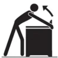
To check if the anti-tip bracket is installed properly, use both arms and grasp the back edge of the range. Carefully attempt to tilt the range forward. When properly installed, the range should not tilt forward.
Refer to the anti-tip bracket installation instructions supplied with your range for proper installation.
Safety codes and Standards
This appliance complies with one or more of the following standards:
• ANSI Z21.1/CSA 1.1 Household Cooking Gas Appliances.
It is the responsibility of the owner and the installer to determine whether additional requirements and/or standards apply to specific installations.
Installation must conform with local codes or, in the absence of local codes, with the National Fuel Gas Code, ANSI Z223.1/NFPA 54 or, in Canada, the Natural Gas and Propane Installation Code, CSA B149.1. The appliance must be electrically grounded in accordance with local codes or, in the absence of local codes, with the National Electrical Code, NFPA 70 latest edition or, in Canada, the Canadian Electric Code, CSA C22.1-02.
36" FULL GAS RANGE INSTALLATION INSTRUCTIONS
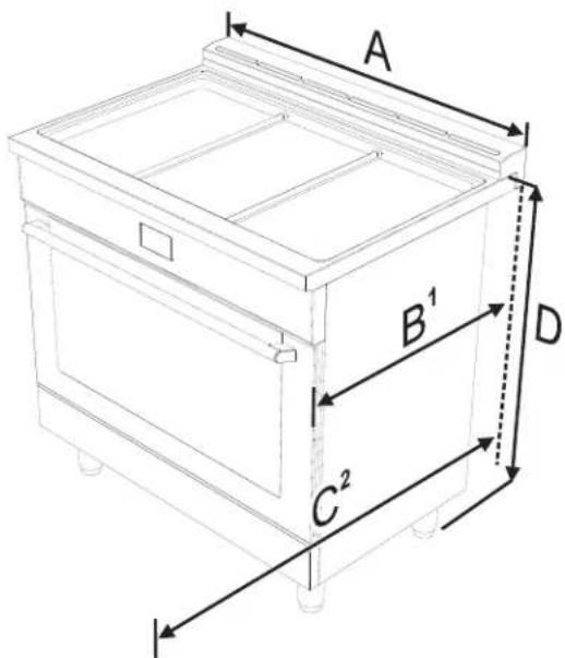
Product Dimensions
text_image
A B¹ C² DA 912.4 mm 35 15/16"
P1 min: 654 mm min: 25 3/4"
max: 658 mm max: 25 7/8"
C2 1116 mm 43 15/16"
D min: 903 mm min: 35 9/16"
max: 929 mm max: 36 9/16"
-
Measurement B varies according to the model: the minimum is obtained without the rear spacers (see "Island installation") and the maximum is obtained for traditional installation (slot-in installation - with the rear spacers).
-
Measurement C refers to the open door.
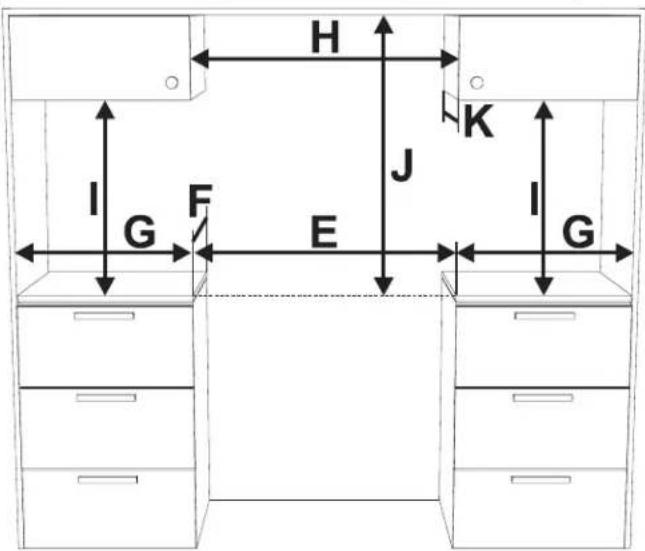
Cabinet clearances
text_image
H I G F E J K G I GClearance J can have the following values:
- J = 42" / 1067 mm minimum clearance between the top of the cooking surface and the bottom of an unprotected wood or metal cabinet.
- J = 30" / 762 mm minimum when the bottom of wood or metal cabinet is protected by not less than 1/4-inch-thick flame-retardant millboard covered with not less than No. 28 MSG sheet steel, 0.015-inch-thick stainless steel, 0.024-inch-thick aluminum, or 0.020-inch-thick copper. Clearances from non-combustible materials are not part of the ANSI Z21.1 scope and are not certified by CSA. Clearances of less than 30" should be approved by the local codes and/or by the local authority having jurisdiction.
36" FULL GAS RANGE INSTALLATION INSTRUCTIONS
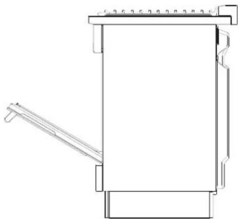
The side cabinet depth (clearance F) must match the front edge of the range side panel:
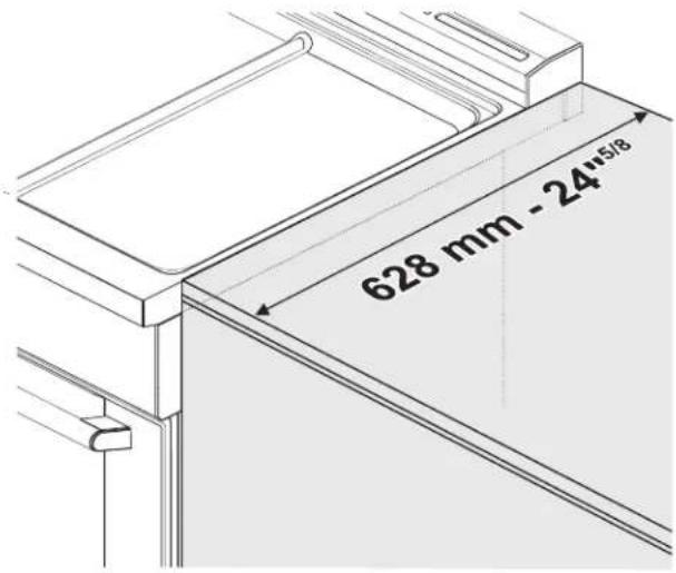
text_image
628 mm - 24"5/18Location of the gas and electric outlets
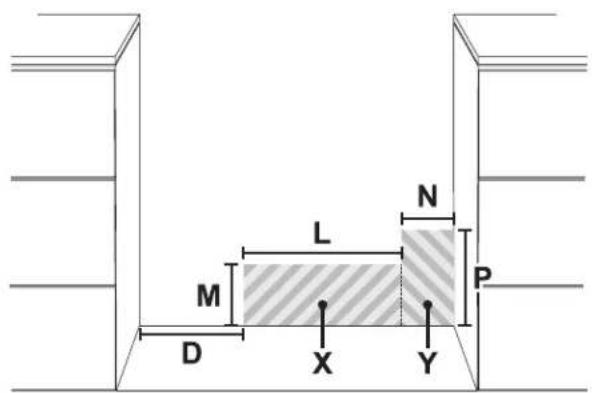
text_image
M D L N P X YD
Min: 11" 7/8 Min: 300 mm
Groun ded outlet (X)
L
Min: 11" 7/8
Min: 300 mm
M
Max: 18" 2/8
Max: 462 mm
Gas sup- ply Line (Y)
N
Min: 2"
Min: 51 mm
N Max: 6"
Max: 152 mm
P
Min: 2"
Min: 51 mm
Max: 10" 7/8
Max: 275 mm
Installing the backguard
The backtrim provided is an integral part of the appliance; it must always be positioned and secured correctly on the cooktop. You can find the assembly instruction for the backtrim in the instructions sheet provided. Once you have fixed the backtrim to the appliance, you must insert the screws and spacers provided that are necessary for the slot-in installation.
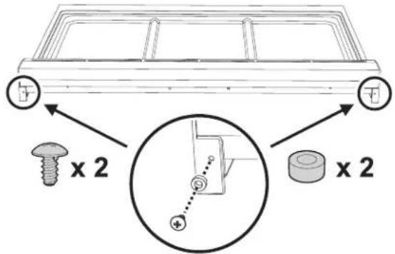
text_image
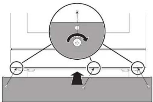
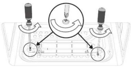
Technical diagram showing a mechanical assembly with screw, nut, and housing components labeled 'x 2' and a magnified inset highlighting a component with plus symbol.Installing the front/side skirting
The front skirting must always be correctly positioned and secured to the appliance.
- Use a screwdriver to remove the front screws.
text_image
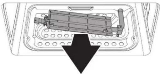
Diagram illustrating a mechanical or electrical setup with labeled components and directional arrows, including a screwdriver.- Position the front skirting at the bottom of the appliance and line up the holes on the side of the skirting with the holes on the base of the appliance.
36" FULL GAS RANGE INSTALLATION INSTRUCTIONS
- Fasten the front skirting to the appliance using the screws that were previously removed.
natural_image
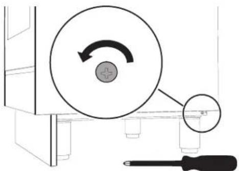
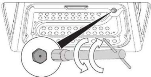
Diagram of a mechanical or fluid system with circular components and directional arrows, no readable text or symbols present.- After the front skirting has been installed, the side skirting can be fastened correctly to the appliance. Use a screwdriver to remove the side screws.
natural_image
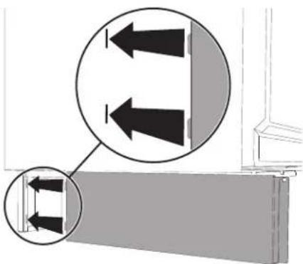
Diagram showing a circular component with an arrow indicating rotation, connected to a screwdriver (no text or symbols present)- Insert the tabs on the side skirting into the slots on the back of the front skirting.
natural_image
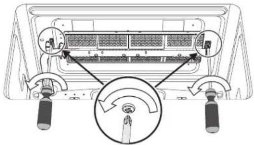
Diagram showing two arrows pointing outward from a wall, with a magnified inset highlighting the lower section (no text or symbols)-
Line up the hole on the side skirting with the rear hole on the base of the appliance.
-
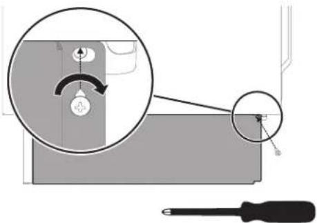
Fasten the side skirting to the appliance using the screw that was previously removed.
text_image
Technical diagram showing a screwdriver tool interacting with a mechanical component, with an inset close-up highlighting a curved component.- Repeat the procedure for the other side skirting section.
Island installation
If the appliance is installed as an island:
- Unscrew the screws indicated.
- Remove the spacers (A).
- Insert the screws that were previously removed into their seats.
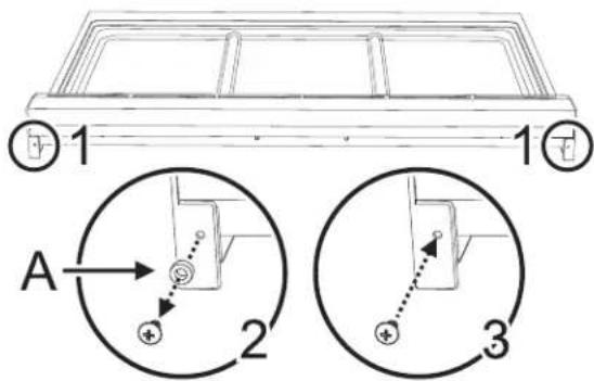
text_image
1 A 2 3Keep a minimum clearance of 5 7/8" (150 mm) between the appliance and the other furnishings or decorative elements according to the diagram below. Keep a minimum clearance of 20" (508 mm) between the appliance and any flammable furniture elements.
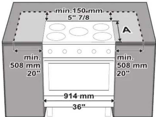
text_image
min.150 mm 5" 7/8 A min. 508 mm 20" min. 508 mm 20" 914 mm 36"36" FULL GAS RANGE INSTALLATION INSTRUCTIONS
The side cabinet depth (clearance A) must match the front edge of the range side panel:
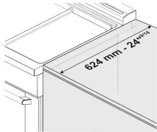
text_image
624 mm - 24"9/16Unpacking, moving and positioning the range
CAUTION
This unit is designed as a cooking appliance. For safety reasons, never use it for warming the room or as a space heater.
- It is recommended that the front kick panel, the backtrim and oven racks be removed to facilitate handling. This will reduce the weight for moving.
- When positioning the appliance during installation, do not use the door handle to lift or move the appliance.
- Wear gloves to avoid cutting fingers on sharp edges during installation.
- Remove the outer carton and packing material from the shipping base.
- The appliance can be moved with a hand dolly or with a clamp lift truck (not with a fork lift truck) only if it is still packaged.
- Remove all tape and packaging before using the appliance. Dispose of the packaging after unpacking the appliance. Never allow children to play with packaging material.
- Due to its weight, after removing the packing material, move it with the help of a second person.
- Before moving range ensure legs are installed completely. Adjust level only when appliance is in final location.
- Before moving range ensure legs are installed completely.
- The floor under the legs should be protected (wood, strips, carpet, paneling, etc.) before pushing the unit into position.
- The anti-tip device must be installed, and the gas / electrical connections should be made before the range is placed in its final position.
- Legs should be installed near to where the appliance will be used as they are not secure for long transit. Keep the unit raised so that the legs can be screwed into their couplings, then lower the range gently to prevent the legs and mounting hardware from being subject to any undue strain.

natural_image
Diagram of a mechanical component with rotating arrows indicating rotational motion (no text or symbols)NOTE: First insert the front feet and then the rear ones.
The following is the correct order of installation and positioning:
- Install and adjust the legs.
- Install the front/side skirting.
- Assemble and fix the anti-tip bracket to the floor or wall.
- Make the gas and electrical connections.
- Move the range to its final position.
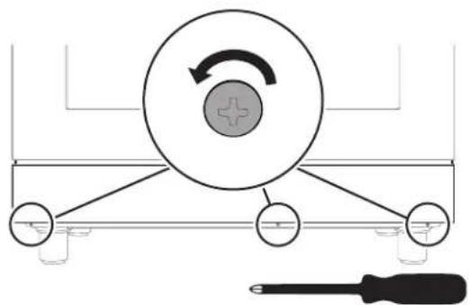
36" FULL GAS RANGE INSTALLATION INSTRUCTIONS
The appliance must sit level on the floor to ensure stability
- Screw or unscrew the bottom part of the foot until the appliance is stable and level on the floor. The adjustment range of the screw is 1.37 inches (35 mm).
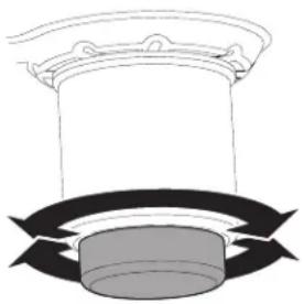
natural_image
Simple line drawing of a column with a circular base and curved arrows indicating rotation or flow (no text or symbols)NOTE: this appliance must only use the specific leveling legs provided by the manufacturer.
Ventilation recommendations:
- We strongly recommend the installation of a ventilation hood above this appliance. The hood must be installed according to the instructions provided with the hood.
! CAUTION
The appliance should not be
installed with a ventilation system that blows air downward toward the burners. This type of ventilation system may cause ignition and combustion problems with the gas cooking appliance and may result in personal injury or unintended operation.
Electrical connection
WARNING

Electrical shock hazard
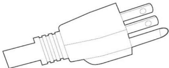
- This appliance is equipped with a four-prong grounding plug for your protection against electric shock and should be plugged directly into a properly grounded receptacle. Do not cut or remove the grounding prong from this plug.
- The grounding prong must be plugged into a matching grounding type receptacle and connected to a correctly polarized 240-Volt circuit. If there is any doubt as to whether the wall receptacle is properly grounded, have it checked by a qualified electrician.
Failure to do any of the above could result in a fire, personal injury or electrical shock.
36" FULL GAS RANGE INSTALLATION INSTRUCTIONS
! WARNING

Electrical shock hazard
- For personal safety, this appliance must be properly grounded. For maximum safety, the power cord must be securely connected to an electrical outlet or junction box that is the correct voltage, is correctly polarized and properly grounded, and protected by a circuit breaker in accordance with local codes.
- It is the personal responsibility of the consumer to have the appropriate outlet or junction box with the correct, properly grounded wall receptacle installed by a qualified electrician. It is the responsibility and obligation of the consumer to contact a qualified installer to ensure that the electrical installation is suitable and in conformance with all local codes and ordinances.
This range is equipped with a factory-connected power cord. The cord must be connected to a grounded 120 volt - 60 Hz outlet. If no outlet is available, have one installed by a qualified electrician.
natural_image
Line drawing of a three-pin electrical plug (no text or symbols)CAUTION
Do not use multiple outlets, exten- dapters.
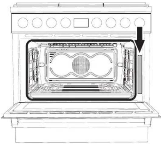
See the rating plate for technical specifications. The rating plate is visibly located on the right side of the oven door frame.
This ID plate must never be removed.
natural_image
Line drawing of an oven interior showing internal components and a downward arrow indicating a component (no text or symbols present)Gas safety
WARNING
Burning gas cooking fuel gener-
ates some by-products which are on the list of sub- stances which are known by the State of California to cause cancer or reproductive harm. To minimize exposure to these substances, always operate this unit according to the instructions contained in this booklet and provide good ventilation.
Install a gas shutoff valve near the appliance. It must be easily accessible in an emergency.
Leak testing must be conducted by the installer according to the instructions in this manual. The appliance and its individual shutoff valve must be disconnected from the gas supply piping system during any pressure testing at pressures in excess of 12 psi (3.5 kPa).
The appliance must be isolated from the gas supply piping system by turning off its individual manual shutoff valve during any pressure testing of the gas supply piping system at test pressures equal to or less than 12 psi (3.5 kPa). The minimum supply pressure must be 1" water column above the manifold pressure printed on the rating label. The maximum supply pressure of 14.0 inches water column (34.9 Millibars) must not exceed.
36" FULL GAS RANGE INSTALLATION INSTRUCTIONS
IMPORTANT SAFETY NOTICE: Burning gas cooking fuel generates some by-products which are on the list of substances which are known by the State of California to cause cancer or reproductive harm. To minimize exposure to these substances, always operate this unit according to the instructions contained in this booklet and provide good ventilation.
WARNING State of California Proposition 65 Warning:
This product may contain a chemical known to the State of California, which can cause cancer or reproductive harm. Therefore, the packaging of your product may bear the following label as required by California. For more information go to www.P65Warnings.ca.gov
Propane gas installation
The propane gas tank must be equipped with its own high pressure regulator. In addition, the regulator supplied with this unit must also be used. The appliance is shipped from the factory for use with natural gas. It must be converted for use with propane. The conversion must be done by a qualified technician or installer. This appliance has been certified for safe operation up to a height of 10,000 ft. Exception: To use it with propane gas, the appliance must be converted in accordance with the propane conversion instructions.
For Massachusetts installations:
- Installation must be performed by a qualified or licensed contractor, plumber or gas fitter qualified or licensed by the state, province or region where this appliance is being installed.
- Shut-off valve must be a "T" handle gas cock.
- Flexible gas connector must not be longer than 36 inches.
Installer - show the owner where the gas shut-off valve is located.
Gas connection
The appliance is shipped from the factory for use with natural gas at a pressure of 5" of water column. When checking if the regulator is working properly, the inlet pressure must be at least 1" greater than the operating (manifold) pressure above. When used with natural gas, the pressure supplied to the regulator must be between 6" and 10.5" of the water column.
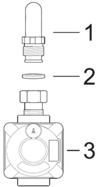
To convert the appliance to propane gas see "Conversion to Propane gas (LPG)". The conversion must be done by a qualified technician or installer. Use a flexible gas pipe with a length of at least 5 ft (1.5 m). The gas inlet to the unit is located at the back right of the appliance. Install the pressure regulator (supplied with the unit) on the gas inlet. Install the gasket (supplied with the unit) between the inlet and the regulator. Position the regulator so that the cap D is easily accessible. Tighten the nut on the gas inlet so that it is hand tight plus 1/3 turn. Connect the gas pipe to the regulator using Teflon tape or pipe-joint compound (resistant to propane gas and natural gas). Turn so that it is hand tight plus 1/3 turn. Do not exceed 1 turn for alignment, to prevent possible damage to the gas pressure regulator.
text_image
1 2 31 Gas inlet (attached to the appliance).
2 Gasket.
3 Pressure regulator.
CAUTION Do not allow regulator to rotate on pipe when tightening fittings.
WARNING Do not attempt to adjust the pressure regulator, except when converting to propane. Adjustments could lead to leaks or cause incorrect gas pressure being supplied to the appliance.
36" FULL GAS RANGE INSTALLATION INSTRUCTIONS
Burners and nozzles technical tables
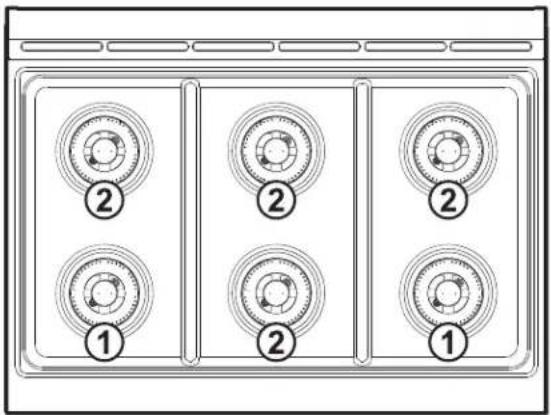
Cooktop burners:
text_image
Diagram of a multi-panel appliance with numbered circular components, likely indicating status or function labels.| Burner power and bypass table | ||
| Burner No. | 1 | 2 |
| Max. Power (BTU) | 18000 12000 | |
| Min. Power (BTU) | 750 750 | |
| Bypass (mm) | 75 / 26 55 / 26 | |
| Natural gas nozzles table (Pressure in W.C.P.: 5") | ||
| Burner No. | 1 | 2 |
| Ext. nozzle number | 180 135 | |
| Int. nozzle number | 75 75 | |
| LPG nozzles table (Pressure in W.C.P.: 10") | ||
| Burner No. | 1 | 2 |
| Ext. nozzle number | 11591 | |
| Int. nozzle number | 4848 | |
Oven cavity burners:
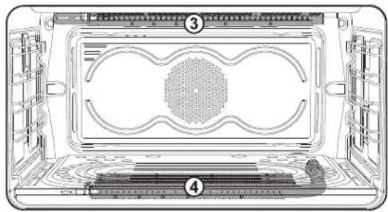
natural_image
Diagram of a microwave oven interior showing internal components and labeled parts (no text or symbols present)3: Broiler burner
4: Oven burner
| Broiler and oven burners power table | ||
| Burner No. | 3 | 4 |
| Power (BTU) | 14000 17000 | |
| Natural gas nozzles table (Pressure in W.C.P.: 5") | ||
| Burner No. | 3 | 4 |
| Nozzle number | 165 180 | |
| LPG nozzles table (Pressure in W.C.P.: 10") | ||
| Burner No. | 3 | 4 |
| Nozzle number | 110 117 | |
Location of the appliance's Gas and Electric connections
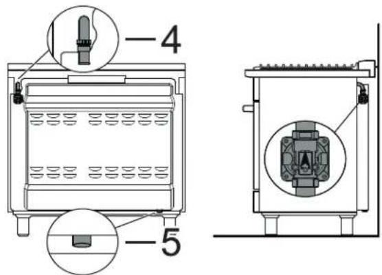
text_image
Technical diagram of a portable oven with labeled components and cross-sectional views4 Gas connection
5 Electrical connection
36" FULL GAS RANGE INSTALLATION INSTRUCTIONS
Connect the gas supply line to the unit pressure regulator using a 1/2" flex gas line connector between the manual shut-off valve and the pressure regulator. A metal flex line or fixed metal pipe must be used to connect the gas to the appliance. If a metal gas line cannot be used, consult your local certified electrician or local electric codes for proper grounding.
Check the supply line connections for leaks using a soap solution or non-corrosive leak detection fluid. Do not use a flame of any sort.
WARNING Install a gas shutoff valve near the appliance. After installation, it must be easily accessible in an emergency.
- Turn on gas.
- Apply a soap solution or non-corrosive leak detection fluid to all joints and fittings in the gas connection between the shut-off valve and the cooktop. Include gas fittings and joints in the cooktop if connections may have been disturbed during installation. Bubbles appearing around fittings and connections indicate a leak.
- If you detect a leak, turn off supply line gas shut-off valve and tighten connections.
- Retest for leaks by turning the gas supply line shutoff valve on. When the leak check has been completed (no bubbles appear), the test is complete.
- Wipe off all residues of the soap solution or detection fluid.
Important Notes for Gas Connection:
- The appliance and its individual gas shutoff valve must be disconnected from the gas supply piping system during pressure testing of the system at test pressures in excess of 1/2 psi (3.5kPa).
- The appliance must be isolated from the gas supply piping system by turning off its individual manual shut-off valve during pressure testing of the gas supply piping system at test pressures equal to or less than 1/2 psi (3.5kPa).
Testing for gas leaks
WARNING NEVER use a flame to check for gas leaks.
Gas leak tests should be performed before the testing the electric ignition of the burners:
- Turn on gas supply.
- Apply a non-corrosive leak detection fluid (e.g. soapy water) to all joints and conduits.
- If bubbles appear, it means there is a leak. Turn off the gas supply and tighten the connections.
- Retest for leaks. If no bubbles appear, the test is passed. Wipe off all residues of detection fluid.
Testing the electric ignition of the burners
This test should be performed after the range and supply line connectors have been carefully checked for leaks and the range connected to the electric power supply:
- Push in and turn a surface burner knob to the low flame position. You will hear the igniter sparking.
- The surface burner should light when gas is supplied to the cooktop burners. Each burner should light within four (4) seconds, after air has been purged from supply lines. Visually check that burner has lit.
- Once the burner lights, the control knob should be rotated out of the low flame position.
- There are separate ignition devices for each burner. Try each knob separately and together until all burner valves have been checked.
36" FULL GAS RANGE INSTALLATION INSTRUCTIONS
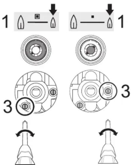
Adjusting the minimum gas setting
Since all cooktop burners are of the dual-flame type, the minimum gas setting must be adjusted for both the outer and inner rings.
These instructions refer to a single burner. Repeat the following for each cooktop burner.
- Push in the burner control knob and light it at the
minimum position
- Remove the burner control knob, along with the conical spring and knob ring.
- Tighten or loosen the highlighted screws to adjust the minimum flame height.
text_image
1 1 3 3Conversion to Propane gas (LPG)
! WARNING
- Before proceeding with the gas conversion, the gas supply must be turned off before disconnecting the electrical power.
- A gas leak test should be performed after the gas conversion has been carried out.
Always provide an adequate gas supply.
This appliance is shipped from the factory for use with natural gas. Use this kit to convert the appliance for use with propane gas, if necessary. Comply with the following: Ensure that the range is converted for use with the appropriate gas before using it.
This appliance is designed to operate at a pressure of 10" of water column when used with propane gas.
When checking if the regulator is working properly, the inlet pressure must be at least 1" greater than the operating (manifold) pressure above. When converting for propane gas use, the pressure supplied to the regulator must be between 11" and 13" of the water column.
The pressure regulator located in the inlet of the range manifold must remain in the supply line.
Use a flexible metal appliance connector or rigid pipe to connect the range to the gas supply. The connector should have an inside diameter of 1/2" and be 5 ft (1.5 m) or less in length.
(Exception: Maximum connector length in Massachusetts installations is 3 ft (0.9 m). In Canada, the connector must be single-wall metal and not longer than 6 ft (1.8 m).
Save the nozzles removed from the appliance for future use.
CAUTION Before proceeding with the gas conversion, the gas supply must be turned off before disconnecting the electrical power.
Parts included with the propane gas nozzle kit:
6 x nozzle number 48
4 x nozzle number 91
2 x nozzle number 115
1 x nozzle number 110
1 x nozzle number 117
1 x adhesive label for LPG nozzles
1 x nozzles change warning label
1 x sealing gasket
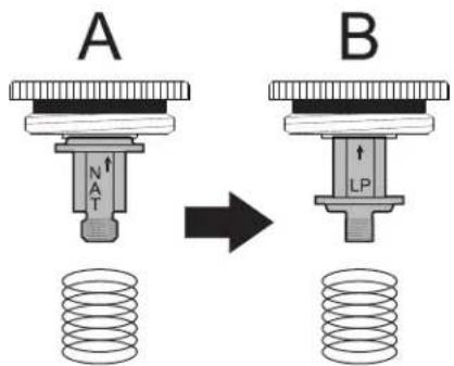
Setting the pressure regulator for Propane Gas
- Unscrew regulator cap.
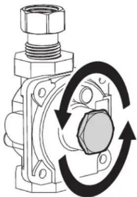
natural_image
Mechanical component diagram showing a bolted joint with rotational arrows indicating motion (no text or symbols)- Unscrew the plastic regulator stem from the regulator cap. Configuration "A" is for Natural Gas.
36" FULL GAS RANGE INSTALLATION INSTRUCTIONS
- Invert the plastic regulator stem to achieve the configuration "B" for Propane Gas and screw it in tightly.
text_image
A B N T LP- Screw the regulator stem and cap into place.
NOTE:
When converting for Propane Gas use, the pressure supplied to the regulator must be between 11" and 13" of the water column.
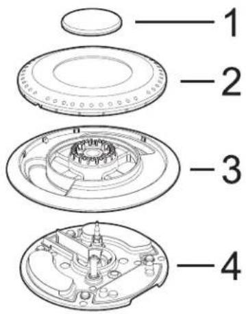
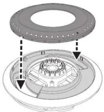
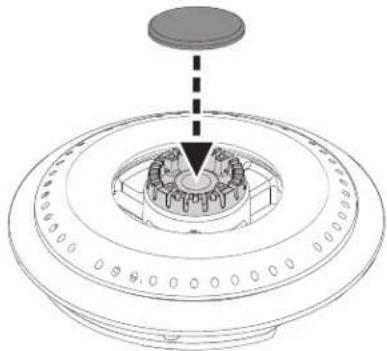
Replacing the cooktop burner nozzles
- Remove the cooktop grates.
- Remove the burner cover (1), the flame-spreader crown (2) and the burner skirt (3) from the burner base (4).
text_image
Exploded view diagram of a mechanical component with numbered parts labeled 1 to 4- Remove the tightening screws (5), the cover plate (6) and the gasket (7).

text_image
5 6 7- Remove the internal (8) and external (9) nozzles and replace them with the LPG nozzles (see "LPG nozzles table (Pressure in W.C.P.: 10")").
text_image
Diagram illustrating mechanical assembly steps with labeled parts and directional arrowsCAUTION This procedure must be performed for every burner.
- Refit the burner components following the above instructions in reverse.
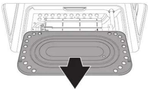
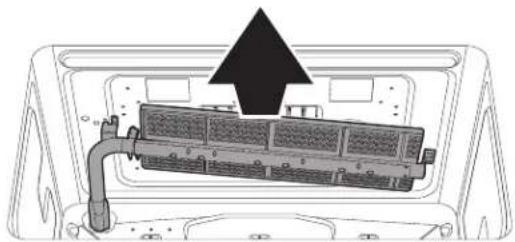
Replacing the oven burner nozzle
CAUTION Take care not to damage the thermocouple or the igniter when doing the following operations.
-
Open the door and remove all the accessories from inside the oven.
-
Remove the shelf.
natural_image
Diagram of a device interior showing a tray with holes and a curved panel with an arrow pointing to the bottom (no text or symbols)36" FULL GAS RANGE INSTALLATION INSTRUCTIONS
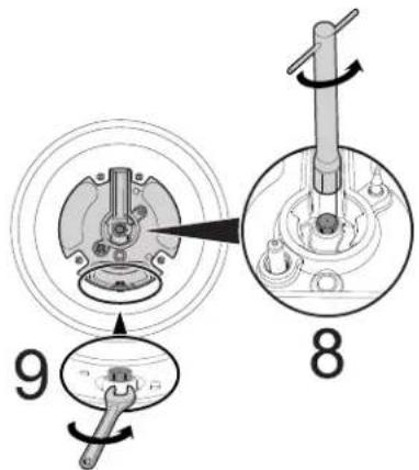
- Remove the oven burner fastening screws from the base.
text_image
Diagram illustrating a mechanical or electrical setup with labeled components and directional arrows indicating motion or movement.- Gently lift the burner at the side and pull it towards you to remove it from its seat.
natural_image
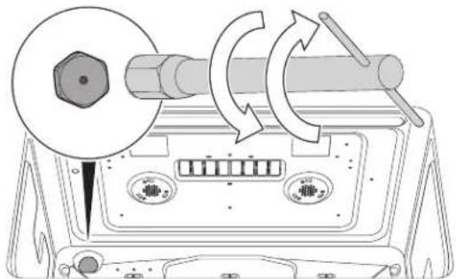
Diagram of a device interior with a highlighted component and arrow indicating direction (no text or symbols)- Replace the nozzle using a 7 mm socket wrench; install the most suitable one for the type of gas used.
natural_image
Diagram of a mechanical device with rotating components and directional arrows indicating motion (no text or symbols)NOTE:
The tightening torque of the nozzle must be 4 Nm.
- After having replaced the nozzle, put the burner back in its seat.
- Tighten the burner fastening screws.
- Put the shelf back in its seat.
Replacing the broiler burner nozzle
CAUTION
Take care not to damage the thermocouple or the igniter when doing the following operations.
-
Open the door and remove all the accessories from inside the oven.
-
Loosen the screws fastening the gas burner with grill to the upper part of the oven.
text_image
Diagram showing a device with labeled parts and directional arrows indicating motion or movement, including a hand gesture.- Gently pull out the burner until the nozzle is accessible.
natural_image
Diagram of a device interior showing a rack-mounted unit with a black arrow pointing to it (no text or symbols present)- Replace the nozzle with the most suitable one for the type of gas used using a 7 mm socket wrench.
natural_image
Diagram of a mechanical device with rotating components and directional arrows indicating motion (no text or symbols)NOTE:
The tightening torque of the nozzle must be 4 Nm.
- After having replaced the nozzle, put the burner back in its seat.
- Tighten the burner fastening screws.
36" FULL GAS RANGE INSTALLATION INSTRUCTIONS
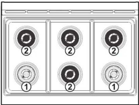
Correct cooktop burners placement
Pay attention to place the burners in their correct zones prior to remounting them.
text_image
Diagram of a refrigerator front panel with six circular buttons labeled 1, 2, and 3, each containing a small circular icon.- 18000 BTU brass coated burners - to be placed in the front left and front right zones.
- 12000 BTU black coated burners - to be placed in all the other zones.
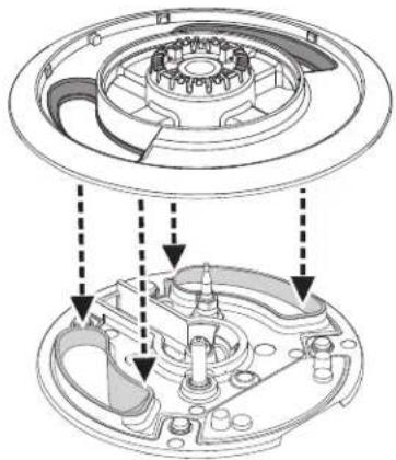
Refitting the cooktop burners
In order to be installed correctly, the shape of the burner skirt openings must match the shape of the openings in the burner base.
natural_image
Technical diagram of a mechanical assembly showing internal components and alignment arrows (no text or labels)The flame-spreader crown must be centered on the burner skirt.
natural_image
Technical diagram of a mechanical assembly showing internal components and alignment arrows (no text or symbols)The burner cover must be leveled and centered with respect to the burner skirt.
natural_image
Technical line drawing of a circular mechanical component with internal gears and a top cylindrical part (no text or symbols)Each burner component must be positioned horizontally and must correctly interlock with each other. Check that they are fitted correctly by moving each component gently. If the components do not fit correctly or are inclined, adjust the position of each component until it remains fixed in position.
36" FULL GAS RANGE INSTALLATION INSTRUCTIONS
Wall and floor attachment
! WARNING

Electrical shock hazard
- Use extreme caution when drilling holes in the wall or floor. There may be concealed electrical wiring behind the wall or under the floor.
- Identify the location of the electrical circuits that could be affected by the installation of the anti-tip device, then turn off power to these circuits.
- Failure to follow these instructions may result in electrical shock or other personal injury.
- Contact a qualified installer or contractor to determine the proper method for drilling holes through the wall or floor material (such as ceramic tile, hardwood, etc.)
- Failure to follow these instructions may result in damage to wall or floor coverings.
CAUTION
WARNING
Visually check from the inside of the drawer that the wall/floor-mounted bracket is inserted into the appropriate lateral hook (left side).
Positioning the bracket using the template:
- Choose the correct side of the template, based on the model.
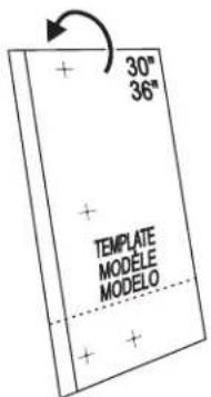
text_image
30" 36" + + TEMPLATE MODELE MODELO + +- Fold the template following the horizontal dashed line.
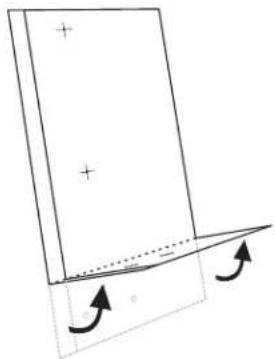
natural_image
Simple line drawing of a rectangular object with plus signs and an arrow indicating rotation, no text or symbols present.- Place the template so that the thick vertical line drawn on it is aligned with the edge of the left side of the appliance.
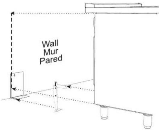
text_image
Wall Mur Pared- Mark the location of the screw holes, to wall or to floor depending of how you want to fix the bracket.
- Fix the anti-tip bracket.
36" FULL GAS RANGE INSTALLATION INSTRUCTIONS
Installing the anti-tip bracket:
- Ensure that the electrical connection is in the correct position.
- Assemble the bracket.
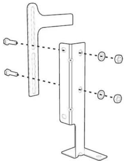
natural_image
Technical line drawing of a metal bracket with mounting holes and dashed alignment lines (no text or symbols)- Align the base of the hook of the bracket with the base on the slot of the rear wall fastening bracket. Align the base of the fastening bracket with the floor and tighten the screws to fix the measurements.
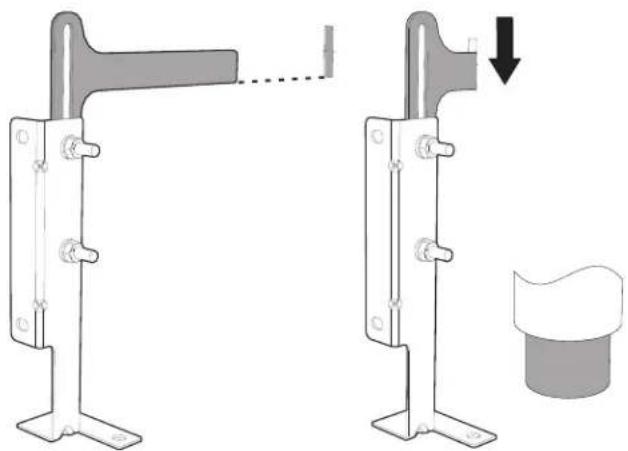
natural_image
Mechanical assembly diagram showing two configurations of a bracket with a handle and a separate cylindrical component (no text or symbols)- For wall mounting, go to steps 5, 6, 9 and 10. For floor mounting, to steps 7, 8, 9 and 10.
NOTE: The wall attachment is recommended if the appliance is placed against a wall. Floor attachment is recommended in case of island installation.
- Use the specified distance from the side of the appliance to the bracket holes.
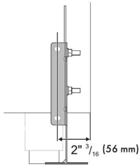
text_image
2"³/₁₆ (56 mm)- Move the bracket to the wall and fix with the two washers and screws. A qualified technician must verify the suitability of the materials in accordance with the type and condition of the wall.
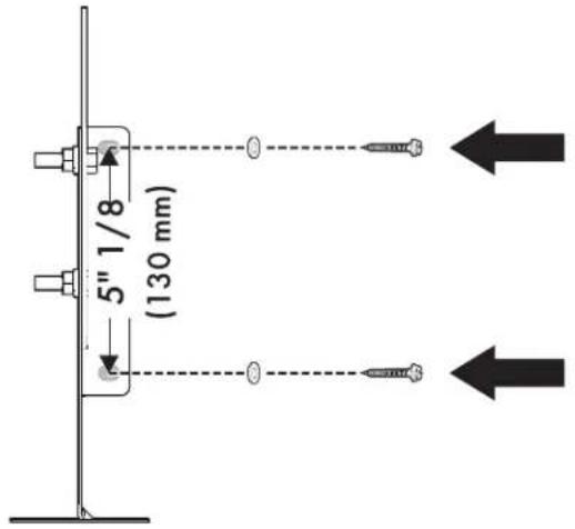
text_image
5" 1/8 (130 mm)36" FULL GAS RANGE INSTALLATION INSTRUCTIONS
- Use the following distances for the distance from the side of the appliance to the bracket holes.
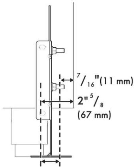
text_image
7/16"(11 mm) 2"5/8 (67 mm)- After having positioned and leveled the appliance, move the bracket close to the rear of the appliance and anchor it to the floor using the two washers and screws. A qualified technician must verify the suitability of the materials in accordance with the type and condition of the floor.
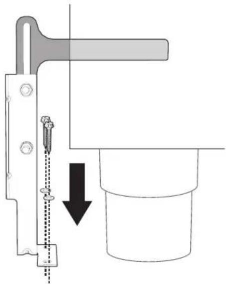
natural_image
Mechanical assembly diagram showing a tool inserted into a cylindrical component with a downward arrow indicating motion (no text or symbols present)- Push the cooker towards the wall, and at the same time, insert the bracket in the plate that is fastened to the rear of the appliance.
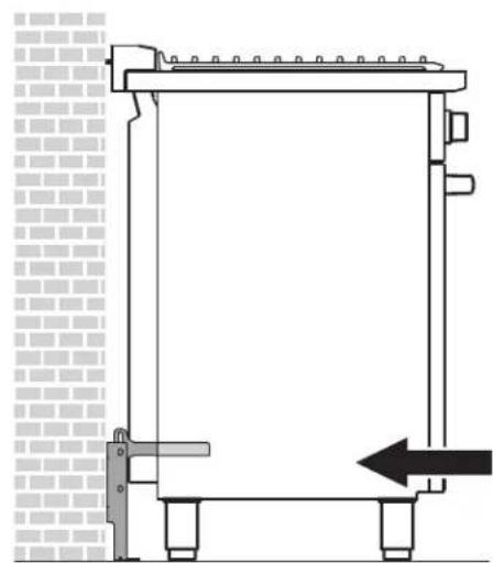
natural_image
Technical line drawing of a mechanical assembly with no visible text or symbolsWARNING The rear vent trim has 3/16" (5 mm) standoffs to keep the appliance slightly away from the back wall. Do not remove or tamper with standoffs due to potential temperature issues.
- Check for proper installation and use of the anti-tip bracket. Carefully tip the range forward by pulling it from the back to ensure that the anti-tip bracket engages the range leg and prevents tip-over. The range should not move more than 1" (2.5cm).
Door removal
It is not necessary to remove the door in order to install the range, but is an added convenience. Refer to the Use and Care Guide for the oven door removal instructions.
natural_image
Technical line drawing of a mechanical device with no visible text or symbolsINSTRUCTIONS D'INSTALLATION CUISINIÈRE À GAZ 36"
L'INSTALLATION ET L'ENTRETIEN DOIVENT ÊTRE EFFECTUÉS PAR UN INSTALLATEUR QUALIFIÉ.
Important Notes to the Installer
natural_image
Silhouette of a person pushing a large block on a flat surface (no text or symbols)text_image
A B¹ C² DA 912.4 mm 35 15/16"
R1 min: 654 mm min: 25 3/4"
B max: 658 mm max: 25 7/8"
C2 1116 mm 43 15/16"
D min: 903 mm min: 35 9/16"
max: 929 mm max: 36 9/16"
text_image
H I G F E J K G I Gtext_image
M D L N P X YD
Min : 11" 7/8 Min : 300 mm
text_image
Diagram showing a car interior with screw, battery, and two circular insets labeled 'x 2' for mechanical or electrical components.natural_image
Diagram of a mechanical assembly with a central rotating component and four connected components, plus a screwdriver (no text or symbols)text_image
Technical diagram showing a mechanical or fluid system with labeled components and directional arrows indicating flow or movement.natural_image
Diagram showing a circular component with an arrow indicating rotation, connected to a screwdriver (no text or symbols present)natural_image
Diagram showing two arrows pointing outward from a panel, with a magnified inset highlighting the structure (no text or symbols present)text_image
Technical diagram showing a screwdriver tool interacting with a mechanical component, with magnified detail highlighting the mechanism.natural_image
Diagram of a mechanical device with rotating arrows indicating rotational motion (no text or symbols)natural_image
Diagram of a column with directional arrows indicating rotation or flow (no text or symbols)natural_image
Line drawing of a three-pin electrical plug (no text or symbols)PRÉCAUTION
natural_image
Technical line drawing of an oven with internal components and a downward arrow indicating a component (no text or symbols present)Sécurité du gaz
! AVERTISSEMENT
La combustion de combust-
text_image
Diagram of a front panel with six circular gauges labeled 1, 2, and 3, each marked with a numbered circle.text_image
Technical diagram of a device interior with labeled components, showing front, top, and side views with numbered annotations.text_image
Technical diagram of a device with labeled components, showing front and side views with numbered parts.natural_image
Mechanical component diagram showing a valve mechanism with rotational arrows (no text or symbols)INSTRUCTIONS D'INSTALLATION CUISINIÈRE À GAZ 36"
text_image
A B N T LPtext_image
Technical diagram illustrating mechanical assembly steps with numbered instructions and labeled componentsnatural_image
Technical diagram of a mechanical component with a highlighted oval section and arrow indicating direction (no text or symbols)INSTRUCTIONS D'INSTALLATION CUISINIÈRE À GAZ 36"
text_image
Diagram illustrating a mechanical or electrical setup with labeled components and directional arrows indicating motion or movement.natural_image
Diagram of a mechanical device inside a housing, showing internal components and a downward arrow indicating direction (no text or symbols)natural_image
Diagram of a mechanical device with rotating components and directional arrows indicating motion (no text or symbols)NOTE:
text_image
Diagram showing a device with labeled parts and directional arrows indicating motion or movement, including a hand gesture.natural_image
Diagram of a device rear panel with a black arrow pointing to a component, no text or symbols presentnatural_image
Diagram of a mechanical device with rotating components and directional arrows indicating motion (no text or symbols)NOTE:
text_image
Diagram of a front panel with six circular buttons labeled 1, 2, and 3, each containing a central icon.natural_image
Technical diagram of a mechanical assembly showing internal components and alignment arrows (no text or labels)natural_image
Technical diagram of a mechanical assembly showing internal components and alignment arrows (no text or symbols)natural_image
Technical diagram of a circular mechanical component with a central gear-like structure and a top cylindrical component (no text or symbols)natural_image
Simple line drawing of a rectangular object with plus signs and an arrow indicating rotation, no text or symbols present.text_image
Wall Mur Parednatural_image
Technical line drawing of a mechanical bracket with mounting holes and dashed alignment lines (no text or symbols)natural_image
Mechanical assembly diagram showing two configurations of a bracket with a close-up view of a cylindrical component (no text or symbols present)natural_image
Diagram of a mechanical assembly with a tool and a cylinder, showing a downward arrow indicating motion (no text or symbols present)natural_image
Technical line drawing of a mechanical assembly with no visible text or symbolsnatural_image
Technical line drawing of a mechanical device with no visible text or symbolsINSTRUCCIONES DE MONTAJE ESTUFA DE GAS DE 36"
Important Notes to the Installer
natural_image
Silhouette of a person pushing a large object on a horizontal line (no text or symbols)Peligro de vuelco
text_image
A B¹ C² DA
912.4 mm 35 15/16"
B ^1
min: 654 mm
min: 25 3/4"
max: 658 mm
max: 25 7/8"
C²
1116 mm 43 15/16"
D
min: 903 mm
min: 35 9/16"
max: 929 mm
max: 36 9/16"
text_image
H I G F E J K I GE
mín. 914 mm mín. 36"
F
628 mm 24" 5/8
G
text_image
L M D X Y N PD
Mín.: 11" 7/8 Mín.: 300 mm
Toma a tierra (X)
L
Mín.: 11" 7/8
Mín.: 300 mm
Máx.: 18" 2/8
Máx.: 462 mm
M
Mín.: 2"
Mín.: 51 mm
Máx.: 9" 7/8
Máx.: 250 mm
text_image
Diagram showing a car front view with screw, battery, and two circular insets highlighting a mechanical component with plus symbol.natural_image
Diagram of a mechanical or electrical component with a circular component and four connected components, plus a screwdriver (no text or symbols)text_image
Technical diagram showing a mechanical or fluid system with rotating components and directional arrows, likely illustrating a physical or engineering concept.natural_image
Diagram showing a mechanical assembly with a rotating wheel and screwdriver, no text or symbols presentnatural_image
Diagram showing two arrows pointing outward from a panel, with a magnified inset highlighting the structure (no text or symbols present)text_image
Technical diagram showing a mechanical assembly with a magnified inset and tool, likely illustrating a turning or disassembly process.natural_image
Diagram of a mechanical device with rotating components and a fan-like top (no text or symbols)natural_image
Diagram of a column with a circular base and curved arrows indicating rotation or force (no text or symbols)natural_image
Line drawing of a three-pin electrical plug (no text or symbols)ATENCIÓN
natural_image
Diagram of an oven with internal air duct and ventilation system, showing no text or symbolsSeguridad del gas
ADVERTENCIA
La quema de gas combustible