Pick your language and provide your email: we'll send you a specifically translated version.
This manual is not available in your language
User questions about M-5000C ROLAND
0 question about this device. Answer the ones you know or ask your own.
Ask a new question about this device
No questions yet. Be the first to ask one.
Download the instructions for your Mixer in PDF format for free! Find your manual M-5000C -
ROLAND and take your electronic device back in hand. On this page are published all the documents necessary for the use of your device. M-5000C by ROLAND.
USER MANUAL M-5000C ROLAND
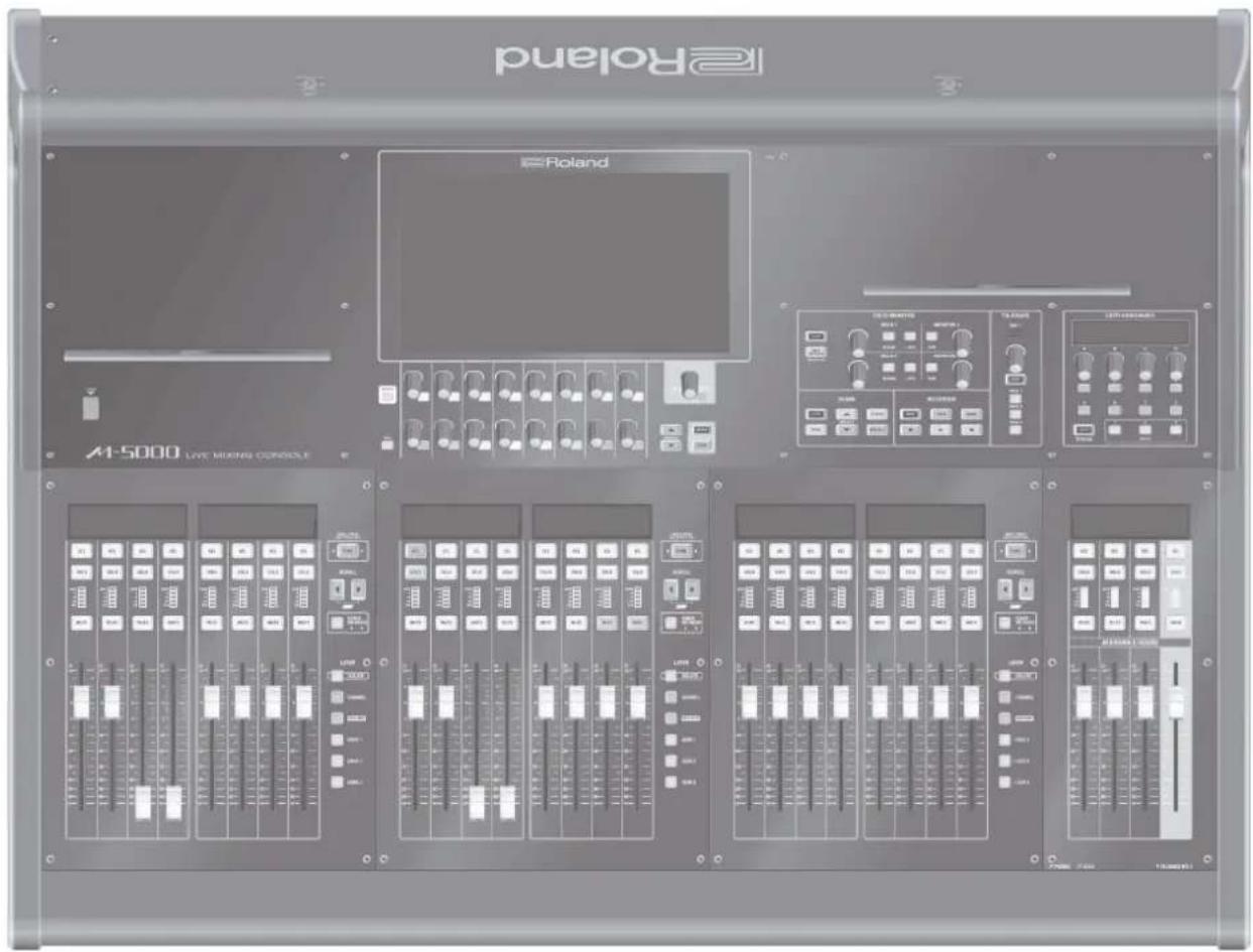
LIVE MIXING CONSOLE M-5000 / M-5000C
Quick Start
text_image
Roland
A1-5000 LIVE MUNING CONSOLE
Roland
Before using the M-5000 / M-5000C, ensure that its system program is at the most recent version. For information on available upgrades for the system program, see the Roland website.
ATTENTION
: RISQUE DE CHOC ELECTRIQUE NE PAS OUVRIR
CAUTION: TO REDUCE THE RISK OF ELECTRIC SHOCK,
DO NOT REMOVE COVER (OR BACK).
NO USER-SERVICEABLE PARTS INSIDE.
REFER SERVICING TO QUALIFIED SERVICE PERSONNEL.
The lightning flash with arrowhead symbol, within an equilateral triangle, is intended to alert the user to the presence of uninsulated “dangerous voltage” within the product’s enclosure that may be of sufficient magnitude to constitute a risk of electric shock to persons.
The exclamation point within an equilateral triangle is intended to alert the user to the presence of important operating and maintenance (servicing) instructions in the literature accompanying the product.
INSTRUCTIONS PERTAINING TO A RISK OF FIRE, ELECTRIC SHOCK, OR INJURY TO PERSONS.
IMPORTANT SAFETY INSTRUCTIONS SAVE THESE INSTRUCTIONS
WARNING - When using electric products, basic precautions should always be followed, including the following:
Read these instructions.
Keep these instructions.
Heed all warnings.
Follow all instructions.
Do not use this apparatus near water.
Clean only with a dry cloth.
Do not block any of the ventilation openings. Install in accordance with the manufacturers instructions.
Do not install near any heat sources such as radiators, heat registers, stoves, or other apparatus (including amplifiers) that produce heat.
Do not defeat the safety purpose of the polarized or grounding-type plug. A polarized plug has two blades with one wider than the other. A grounding type plug has two blades and a third grounding prong. The wide blade or the third prong are provided for your safety. If the provided plug does not fit into your outlet, consult an electrician for replacement of the obsolete outlet.
Protect the power cord from being walked on or pinched particularly at plugs, convenience receptacles, and the point where they exit from the apparatus.
Only use attachments/accessories specified by the manufacturer.
Unplug this apparatus during lightning storms or when unused for long periods of time.
Refer all servicing to qualified service personnel. Servicing is required when the apparatus has been damaged in any way, such as power-supply cord or plug is damaged, liquid has been spilled or objects have fallen into the apparatus, the apparatus has been exposed to rain or moisture, does not operate normally, or has been dropped.
For the U.K.
WARNING: THIS APPARATUS MUST BE EARTHED
IMPORTANT: THE WIRES IN THIS MAINS LEAD ARE COLOURED IN ACCORDANCE WITH THE FOLLOWING CODE. GREEN-AND-YELLOW: EARTH, BLUE: NEUTRAL, BROWN: LIVE
As the colours of the wires in the mains lead of this apparatus may not correspond with the coloured markings identifying the terminals in your plug, proceed as follows:
The wire which is coloured GREEN-AND-YELLOW must be connected to the terminal in the plug which is marked by the letter E or by the safety earth symbol ⊕ or coloured GREEN or GREEN-AND-YELLOW.
The wire which is coloured BLUE must be connected to the terminal which is marked with the letter N or coloured BLACK. The wire which is coloured BROWN must be connected to the terminal which is marked with the letter L or coloured RED.
WARNING
DO NOT INGEST BATTERY, CHEMICAL BURN HAZARD
This product contains a coin/button cell battery. If the coin/button cell battery is swallowed, it can cause severe internal burns in just 2 hours and can lead to death.
Keep new and used batteries away from children. If the battery compartment does not close securely, stop using the product and keep it away from children. If you think batteries might have been swallowed or placed inside any part of the body, seek immediate medical attention.
CAUTION: Danger of explosion if battery is incorrectly replaced.
Replace only with same or equivalent type.
INSTRUCTIONS FOR THE PREVENTION OF FIRE, ELECTRIC SHOCK, OR INJURY TO PERSONS
About ⚠️ WARNING and ⚠️ CAUTION Notices
WARNING
Used for instructions intended to alert the user to the risk of death or severe injury should the unit be used improperly.
CAUTION
Used for instructions intended to alert the user to the risk of injury or material damage should the unit be used improperly.* Material damage refers to damage or other adverse effects caused with respect to the home and all its furnishings, as well to domestic animals or pets.
About the Symbols
The △symbol alerts the user to important instructions or warnings. The specific meaning of the symbol is determined by the design contained within the triangle. In the case of the symbol at left, it is used for general cautions, warnings, or alerts to danger.
The ⬆symbol alerts the user to items that must never be carried out (are forbidden). The specific thing that must not be done is indicated by the design contained within the circle. In the case of the symbol at left, it means that the unit must never be disassembled.
The ●symbol alerts the user to things that must be carried out. The specific thing that must be done is indicated by the design contained within the circle. In the case of the symbol at left, it means that the power-cord plug must be unplugged from the outlet.
ALWAYS OBSERVE THE FOLLOWING
WARNING
Make sure that the power cord is grounded
Connect mains plug of this model to a mains socket outlet with a protective earthing connection.
To completely turn off power to the unit, pull out the plug from the outlet
Turning off the power switch does not completely cut off the main power to the M-5000. When it is necessary to switch off the power completely, turn off the power switch on the M-5000 and the power
switch on any backup power unit connected to the EXT.POWERDCINPUTconnector,thenunplugtheM-5000 from the power outlet. To make this possible, plug the powercordintoapoweroutletthatisasclosetotheM-5000 as possible and can be reached immediately.
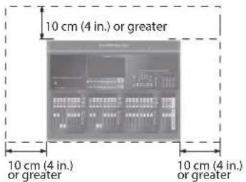
Secure a sufficient amount of space at the setup location
Since this unit normally emits a slight amount of heat, make sure to secure sufficient space around it, as shown below.
text_image
10 cm (4 in.) or greater
10 cm (4 in.)
or greater
10 cm (4 in.)
or greater
Do not disassemble or modify by yourself
Do not carry out anything unless you are instructed to do so in the owner's manual. Otherwise, you risk causing malfunction.
Do not repair or replace parts by yourself
Refer all servicing to your retailer, the nearest Roland Service Center, or an authorized Roland distributor, as listed on the "Information."
WARNING
Do not use or store in the following types of locations
Subject to temperature extremes (e.g., direct sunlight in an enclosed vehicle, near a heating duct, on top of heat-generating equipment); or are
Damp (e.g., baths, washrooms, on wet floors); or are
• Exposed to steam or smoke; or are
Subject to salt exposure; or are
Exposed to rain; or are
• Dusty or sandy; or are
Subject to high levels of vibration and shakiness.
Do not place in an unstable location
Otherwise, you risk injury as the result of the unit toppling over or dropping down.
Connect the power cord to an outlet of the correct voltage
The unit should be connected to a power supply only of the type described as marked on the rear side of unit.
Connect only specified devices to LAMP connector
Connect only compatible lamps to the LAMP connectors.
Use only the supplied power cord
Use only the attached power cord. Also, the supplied power cord must not be used with any other device.
Do not bend the power cord or place heavy objects on it
Otherwise, fire or electric shock may result.
WARNING
Avoid extended use at high volume
Use of the unit at high volume for extended periods of time may cause hearing loss. If you ever experience any hearing loss or ringing in the ears, you should immediately stop using the unit and consult a specialized physician.
Do not allow foreign objects or liquids to enter unit; never place containers with liquid on unit
Do not place containers containing liquid (e.g., flower vases) on this product. Never allow foreign objects (e.g., flammable objects, coins, wires) or liquids (e.g., water or juice) to enter this product. Doing so may cause short circuits, faulty operation, or other malfunctions.
Turn off the unit if an abnormality or malfunction occurs
Immediately turn the unit off, remove the power cord from the outlet, and request servicing by your retailer, the nearest Roland Service Center, or an authorized Roland distributor, as listed on the "Information" when:
• The power cord has been damaged; or
• If smoke or unusual odor occurs; or
- Objects have fallen into, or liquid has been spilled onto the unit; or
- The unit has been exposed to rain (or otherwise has become wet); or
• The unit does not appear to operate normally or exhibits a marked change in performance.
Be cautious to protect children from injury
Always make sure that an adult is on hand to provide supervision and guidance when using the unit in places where children are present, or when a child will be using the unit.
Do not drop or subject to strong impact
Otherwise, you risk causing damage or malfunction.
WARNING
Do not share an outlet with an unreasonable number of other devices
Otherwise, you risk overheating or fire.
Do not use overseas
Before using the unit in overseas, consult with your retailer, the nearest Roland Service Center, or an authorized Roland distributor, as listed on the "Information."
Handle lithium batteries carefully
• Lithium batteries must never be recharged, heated, taken apart, or thrown into a fire or water.
- Keep lithium batteries out of reach of small children. If a child has accidentally swallowed a battery, see a doctor immediately.
- Never expose lithium batteries to excessive heat such as sunshine, fire or the like.
Turn the unit off before installing expansion interface
Before installing the expansion interface (option), you must first always turn off the unit and unplug its power cord.
CAUTION
When disconnecting the power cord, grasp it by the plug
To prevent conductor damage, always grasp the power cord by its plug when disconnecting it from this unit or from a power outlet.
Periodically clean the power plug
An accumulation of dust or foreign objects between the power plug and the power outlet can lead to fire or electric shock.
At regular intervals, be sure to pull out the power plug, and using a dry cloth, wipe away any dust or foreign objects that may have accumulated.
Disconnect the power plug whenever the unit will not be used for an extended period of time
Fire may result in the unlikely event that a breakdown occurs.
Route all power cords and cables in such a way as to prevent them from getting entangled
Injury could result if someone were to trip on a cable and cause the unit to fall or topple.
Avoid climbing on top of the unit, or placing heavy objects on it
Otherwise, you risk injury as the result of the unit toppling over or dropping down.
Never connect/disconnect a power plug if your hands are wet
Otherwise, you could receive an electric shock.
Cautions when moving this unit
Since this product is very heavy, you must make sure that a sufficient number of people are on hand to help, so you can lift and move it safely, without causing strain. Make sure to have a firm grip, to protect yourself from injury and the instrument from damage. If you need to move the instrument, take note of the precautions listed below.
• Disconnect the power cord.
- Disconnect all cords coming from external devices.
Before cleaning the unit, disconnect the power plug from the outlet
If the power plug is not removed from the outlet, you risk receiving an electric shock.
Whenever there is a threat of lightning, disconnect the power plug from the outlet
If the power plug is not removed from the outlet, you risk receiving an electric shock.
CAUTION
Handle lithium batteries carefully
Use only the specified type (model no. CR2032) of lithium batteries (p. 22). Be sure to insert it as directed (to ensure correct polarity).
• Used lithium batteries must be disposed of in compliance with whatever regulations for their safe disposal that may be observed in the region in which you live.
Install only specified expansion interface
Install only the specified expansion interface. Remove only the specified screws (p. 24).
Keep small items out of the reach of children
To prevent accidental ingestion of the parts listed below, always keep them out of the reach of small children.
Included Parts
Ferrite core (p. 15)
REAC connector cover (p. 16)
• Removable Parts
REAC cap (p. 16)
USB cover (p. 15)
Screws
Handle the ground terminal carefully
If you remove the screw from the ground terminal, be sure to replace it; don't leave it lying around where it could accidentally be swallowed by small children. When refastening the screw, make that it is firmly fastened, so it won't come loose.
Precautions concerning use of phantom power supply
Always turn the phantom power off when connecting any device other than condenser microphones that require phantom power. You risk causing damage if you mistakenly supply phantom power
to dynamic microphones, audio playback devices, or other devices that don't require such power. Be sure to check the specifications of any microphone you intend to use by referring to the manual that came with it.
(This instrument's phantom power: DC+48 V, 14 mA Max)
INSTRUCTIONS POUR LA PRÉVENTION DES INCENDIES, CHOCS ÉLECTRIQUES OU BLESSURES
- Do not connect this unit to same electrical outlet that is being used by an electrical appliance that is controlled by an inverter or a motor (such as a refrigerator, washing machine, microwave oven, or air conditioner). Depending on the way in which the electrical appliance is used, power supply noise may cause this unit to malfunction or may produce audible noise. If it is not practical to use a separate electrical outlet, connect a power supply noise filter between this unit and the electrical outlet.
Placement
- Using the unit near power amplifiers (or other equipment containing large power transformers) may induce hum. To alleviate the problem, change the orientation of this unit; or move it farther away from the source of interference.
- This unit may interfere with radio and television reception. Do not use this unit in the vicinity of such receivers.
- Noise may be produced if wireless communications devices, such as cell phones, are operated in the vicinity of this unit. Such noise could occur when receiving or initiating a call, or while conversing. Should you experience such problems, you should relocate such wireless devices so they are at a greater distance from this unit, or switch them off.
- When moved from one location to another where the temperature and/or humidity is very different, water droplets (condensation) may form inside the unit. Damage or malfunction may result if you attempt to use the unit in this condition. Therefore, before using the unit, you must allow it to stand for several hours, until the condensation has completely evaporated.
- Depending on the material and temperature of the surface on which you place the unit, its rubber feet may discolor or mar the surface. You can place a piece of felt or cloth under the rubber feet to prevent this from happening. If you do so, please make sure that the unit will not slip or move accidentally.
- Do not place containers or anything else containing liquid on top of this unit. Also, whenever any liquid has been spilled on the surface of this unit, be sure to promptly wipe it away using a soft, dry cloth.
Maintenance
- Never use benzine, thinners, alcohol or solvents of any kind, to avoid the possibility of discoloration and/or deformation.
Repairs and Data
- Before sending the unit away for repairs, be sure to make a backup of the data stored within it; or you may prefer to write down the needed information. Although we will do our utmost to preserve the data stored in your unit when we carry out repairs, in some cases, such as when the memory section is physically damaged, restoration of the stored content may be impossible. Roland assumes no liability concerning the restoration of any stored content that has been lost.
Memory Backup
- This unit contains a battery which powers the unit's memory circuits while the main power is off. When this battery becomes weak, the message shown below will appear in the display. Once you see this message, have the battery replaced with a fresh one as soon as possible to avoid the loss of all data in memory.
Additional Precautions
Any data stored within the unit can be lost as the result of equipment failure, incorrect operation, etc. To protect yourself against the irretrievable loss of data, try to make a habit of creating regular backups of the data you've stored in the unit.
Roland assumes no liability concerning the restoration of any stored content that has been lost.
Use a reasonable amount of care when using the unit's buttons, sliders, or other controls; and when using its jacks and connectors. Rough handling can lead to malfunctions.
• Never strike or apply strong pressure to the display.
When disconnecting all cables, grasp the connector itself—never pull on the cable. This way you will avoid causing shorts, or damage to the cable's internal elements.
A small amount of heat will radiate from the unit during normal operation.
To avoid disturbing others nearby, try to keep the unit's volume at reasonable levels.
Using External Memories
- Please observe the following precautions when handling external memory devices. Also, make sure to carefully observe all the precautions that were supplied with the external memory device.
Do not remove the device while reading/writing is in progress.
• To prevent damage from static electricity, discharge all static electricity from your person before handling the device.
Intellectual Property Right
It is forbidden by law to make an audio recording, video recording, copy or revision of a third party's copyrighted work (musical work, video work, broadcast, live performance, or other work), whether in whole or in part, and distribute, sell, lease, perform, or broadcast it without the permission of the copyright owner.
Do not use this product for purposes that could infringe on a copyright held by a third party. We assume no responsibility whatsoever with regard to any infringements of third-party copyrights arising through your use of this product.
MMP (Moore Microprocessor Portfolio) refers to a patent portfolio concerned with microprocessor architecture, which was developed by Technology Properties Limited (TPL). Roland has licensed this technology from the TPL Group.
• ASIO is a trademark and software of Steinberg Media Technologies GmbH.
This product is using the open source license (GPL/LGPL) software. You have the right to acquire, modify and distribute the source code for this open source license software. You can obtain the open source license source code used in this product by downloading it from the following website: URL:http://www.roland.com/support/gpl/
This product contains eParts integrated software platform of eSOL Co., Ltd. eParts is a trademark of eSOL Co., Ltd. in Japan.
"Made for iPod," means that an electronic accessory has been designed to connect specifically to iPad and has been certified by the developer to meet Apple performance standards. Apple is not responsible for the operation of this device or its compliance with safety and regulatory standards. Please note that the use of this accessory with iPad may affect wireless performance. Apple, Macintosh, Mac OS, iPad are either registered trademarks or trademarks of Apple Inc.
Roland, REAC are either registered trademarks or trademarks of Roland Corporation in the United States and/or other countries.
• Company names and product names appearing in this document are registered trademarks or trademarks of their respective owners.
Before using this unit, carefully read the sections entitled "IMPORTANT SAFETY INSTRUCTIONS" (p. 2), "USING THE UNIT SAFELY" (p. 4), and "IMPORTANT NOTES" (p. 8). After reading, keep the document(s) including those sections where it will be available for immediate reference.
The explanations in this manual include illustrations that depict what should typically be shown by the display. Note, however, that your unit may incorporate a newer, enhanced version of the system (e.g., includes newer sounds), so what you actually see in the display may not always match what appears in the manual.
This manual describes the basic matters and basic operation of the M-5000 and M-5000C live mixing consoles.
In descriptions of matters and operation procedures that are common to both the M-5000 and M-5000C, the two models are referred to collectively as "the M-5000."
Matters that are specific to only one or the other model are indicated by "M-5000 only" or "M-5000C only."
When "the M-5000 is depicted" or the like is noted, the description uses the M-5000 as representative of both the M-5000 and the M-5000C.
Organization of the Documentation
The documentation for this unit is organized as follows.
Quick Start (this document)
This describes the basic matters and procedures necessary for unit operation and quick startup.
Reference Manual (PDF)
This adds to the information in Quick Start by describing the operational features on the various screens and other detailed usage methods.
RCS User's Guide (PDF)
This describes how to use the M-5000 RCS dedicated remote-control software that runs under Windows or on a Macintosh computer.
Remote User's Guide (PDF)
This describes how to use the M-5000 Remote dedicated remote-control software that runs on an iPad.
Telnet Reference Manual (PDF)
This describes how to control the M-5000 over a local area network (TCP/IP protocol), using Telnet.
MIDI Implementation (PDF)
This describes the MIDI messages that the M-5000 supports.
RS-232C Reference Manual (PDF)
This describes the RS-232C interface commands that the M-5000 supports.
The PDF-format versions of documentation can be downloaded from the Roland website.
French language
for Canadian Safety Standard
IMPORTANT SAFETY INSTRUCTIONS 2
INSTRUCTIONS IMPORTANTES
DE SÉCURITÉ
French language
for Canadian Safety Standard .... 3
USING THE UNIT SAFELY 4
CONSIGNES DE SÉCURITÉ French language for Canadian Safety Standard
IMPORTANT NOTES 8
About the Documentation.... 9
Main Features.... 12
Placement and Setup 15
Included Items 15
Attaching the Ferrite Cores 15
Detaching the USB cover (M-5000C only) 15
Detaching the REAC Caps.... 16
Attaching the REAC Connector Covers 16
Connecting the Power Cord.... 16
Using the Power-cord Clamp.... 16
Using the Power-cord Hook.... 18
Connecting Backup Power to the M-5000.... 18
Disconnecting Backup Power 20
Turning the Power On and Off.... 20
Turning the Power On 20
Turning the Power Off 20
Replacing the Internal Lithium Battery 22
Attaching the Tablet Sheets.... 22
Installing an Expansion Interface (Option) 24
Using the LAN-cable Hook.... 24
French language for Canadian Safety Standard
Installing REAC Devices 26
Basic REAC Knowledge 26
About Cables 26
Ethernet Cable Types 26
Ethernet Connectors 26
Important Notes on Handling Ethernet Cables.... 26
Connecting REAC Input/Output Units 27
Important Notes on REAC Connections 27
Part Names and Functions 28
Top Panel.... 28
Fader Bank Section.... 30
Assignable Fader Section 31
USB MEMORY Connector 31
Display Section 32
Monitor Section 33
Scene Section 34
Recorder Section.... 34
Talkback Section.... 35
User-assignable Section 36
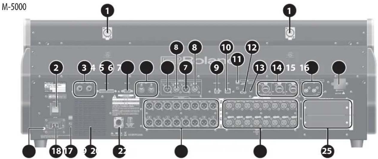
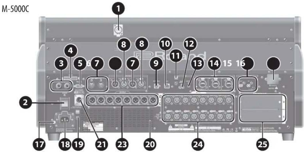
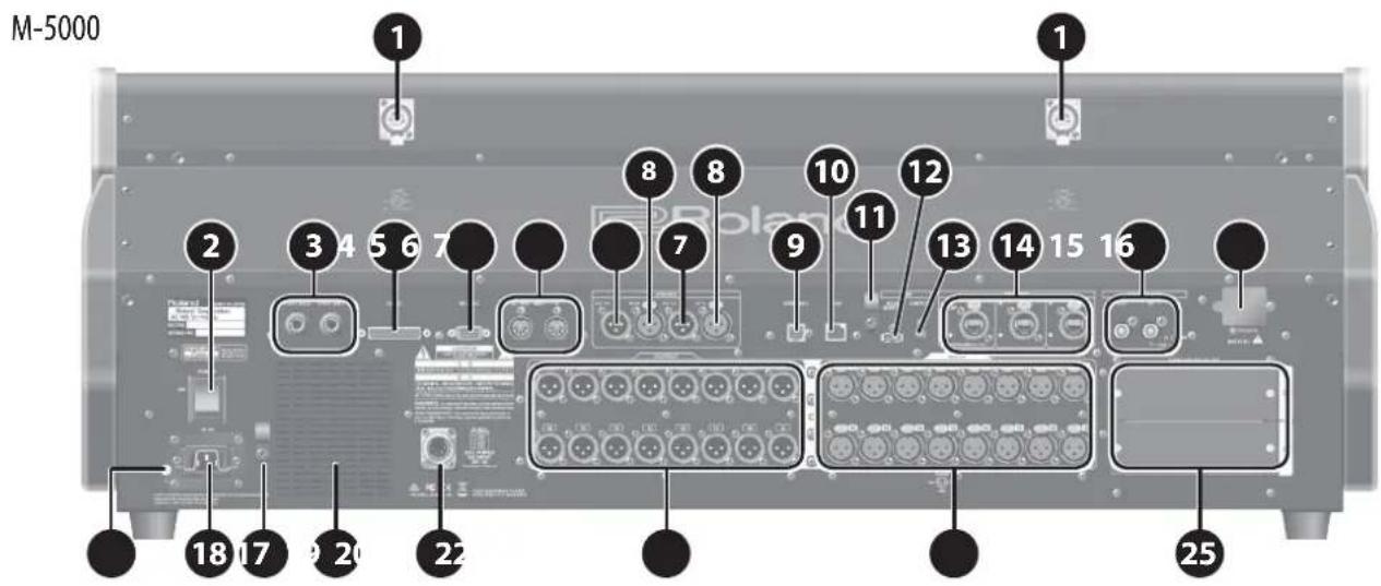
Rear Panel 38
Front Panel 44
French language for Canadian Safety Standard
Panneau arrière 39
Panneau avant 45
Overview of Operations.... 46
Fader Bank Section 46
Layers 46
Scrolling 46
Basic Operations of Fader Bank Section.... 46
Changing Layers 46
Scrolling the Channels.... 46
Anchor Channels 47
Accessing an Anchor Channel (Anchor Jump) 47
Accessing Adjacent Anchor Channels.... 47
Isolated Banks.... 48
Isolating a Fader Bank 48
Unisolating a Fader Bank.... 48
Basic Touch Operations.... 49
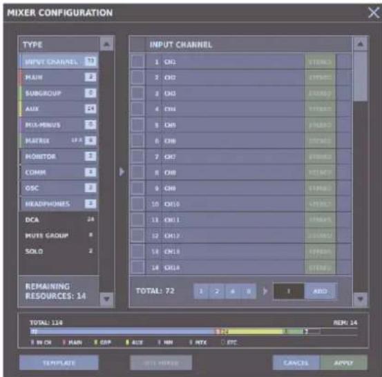
Using Templates to Select a Mixer Configuration 49
HOME Screen 50
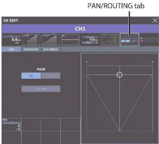
Access the CH EDIT window.... 50
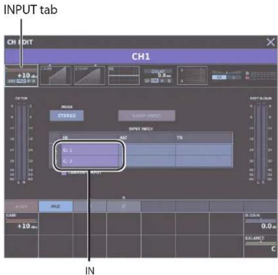
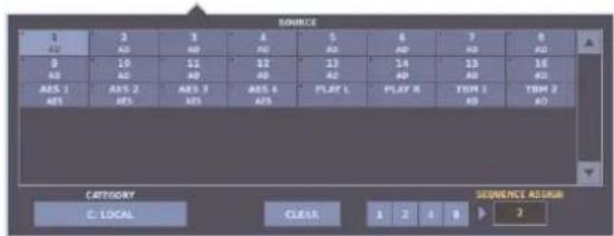
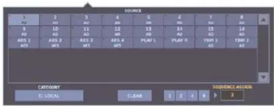
Selecting the Source for an Input Channel 51
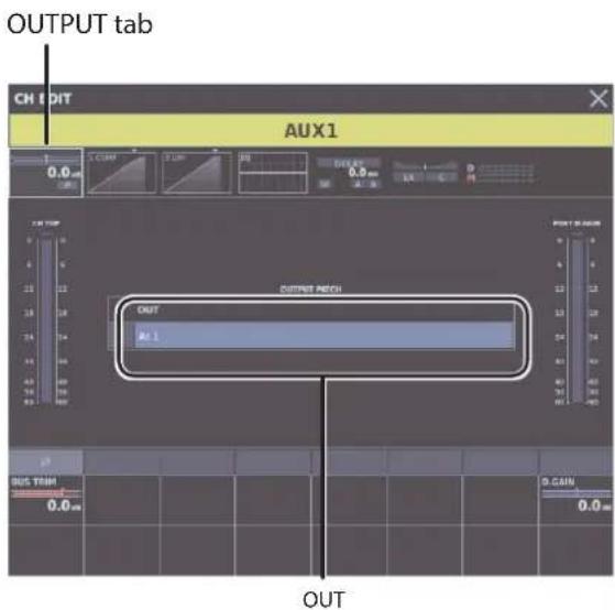
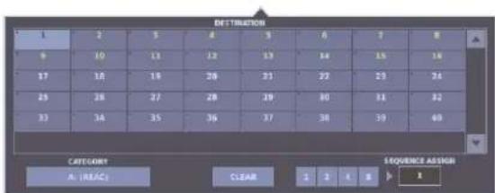
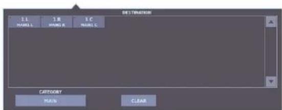
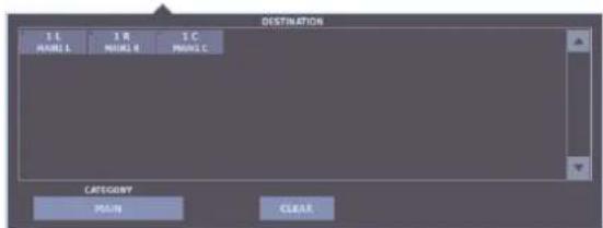
Selecting the Destination for an Output Bus 51
Turning Phantom Power On or Off 52
Adjusting the Preamp Gain 52
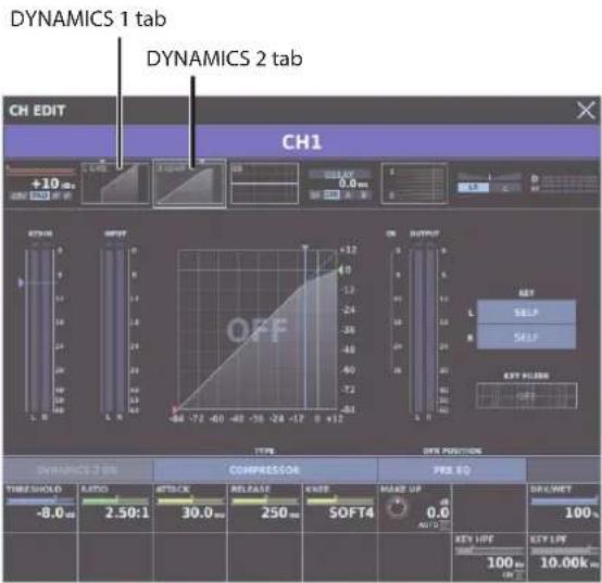
Applying Dynamics 53
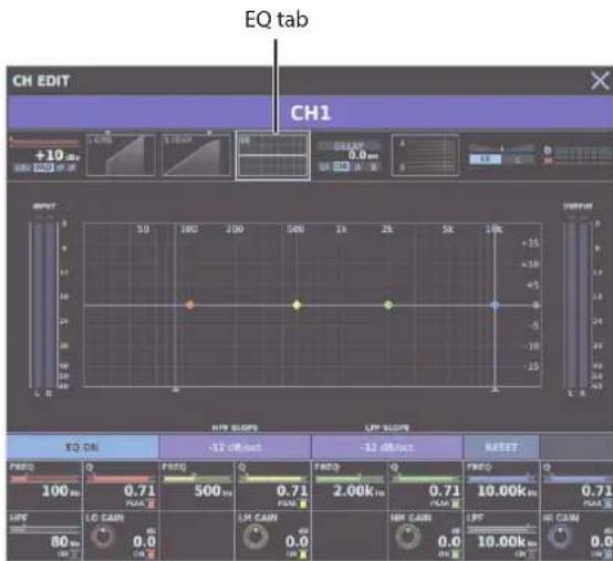
Applying EQ 53
Using Faders to Adjust the Send Level to AUX (SENDS ON FADER).. 53
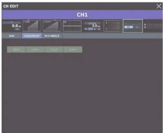
Sending to SUBGROUP/MIX-MINUS 54
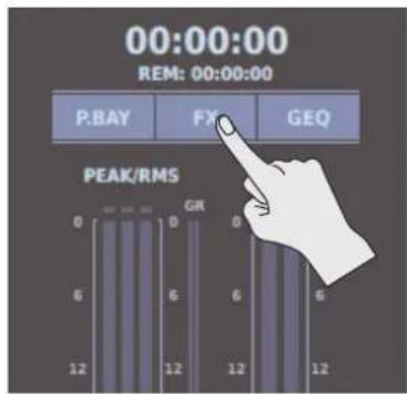
Using an FX with Send/Return 54
Inserting an FX 55
Inserting a GEQ 56
Linking Channels 57
Making Assignments to DCA/MUTE Groups.... 58
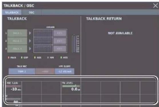
Using Talkback 58
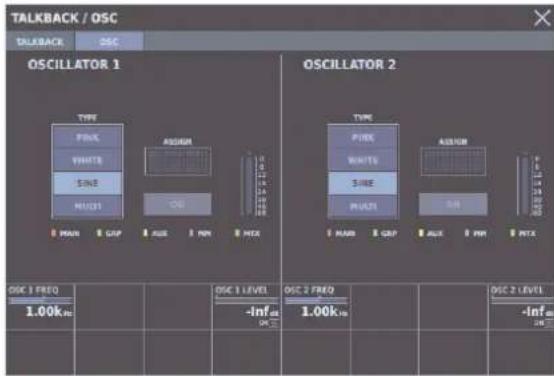
Using the Oscillators 59
Scene memory 59
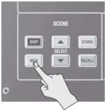
Creating New Scenes and Adding Scenes 59
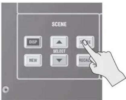
Storing a Scene (by Overwriting).... 59
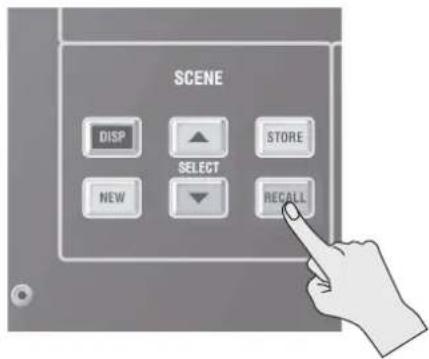
Recalling a Scene 60
Recording/Playback to/from a USB Flash Drive 60
WAV File Formats 60
Recording to a USB Flash Drive 60
Playback from a USB Flash Drive 61
Backing Up All Data in the M-5000....61
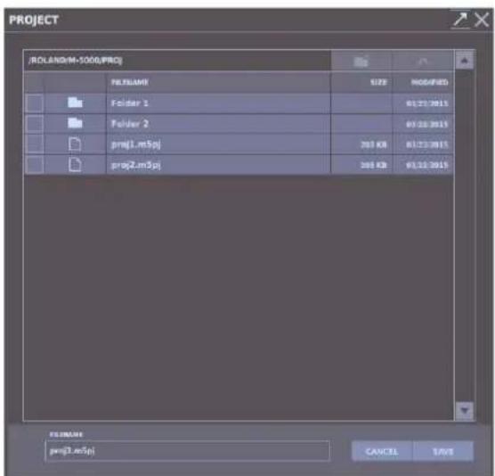
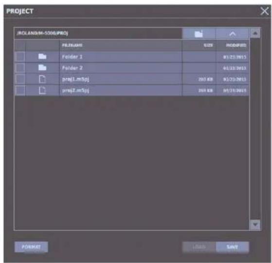
Saving a Project File to a USB Flash Drive.... 61
Restoring All Data in the M-5000 62
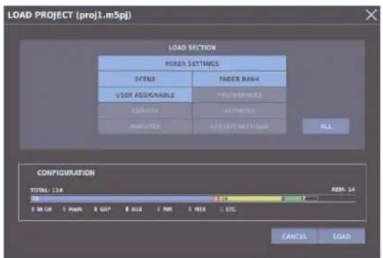
Loading a Project File from a USB Flash Drive 62
Formatting a USB Flash Drive on the M-5000....62
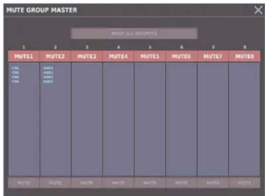
Muting All Outputs 62
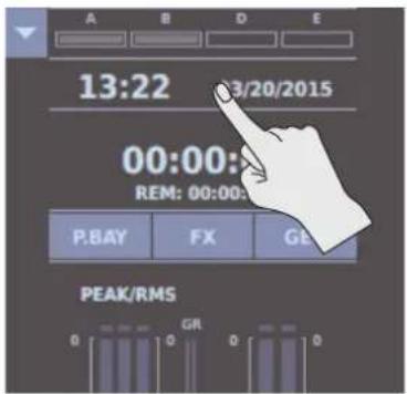
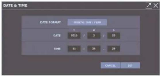
Setting the Date and Time 63
Factory Reset 63
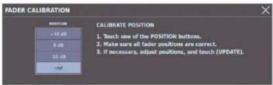
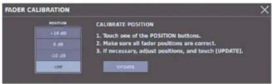
Fader Calibration 63
Appendix 64
Main specifications 64
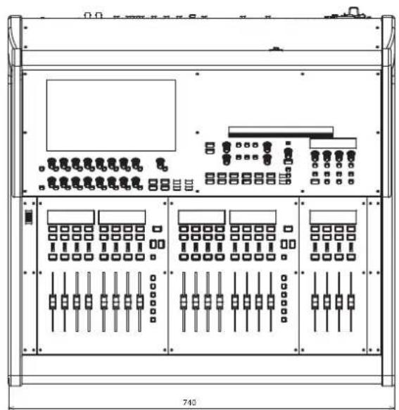
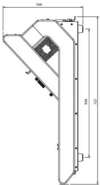
Dimensions.... 66
The M-5000 is Roland's next-generation flagship mixing console, featuring an ideal user interface for operating a 96-kHz mixing engine loaded with original Roland technology.
The M-5000 can flexibly transform its configuration and functions to accommodate a wide range of situations with its large complement of outstanding features.
The following key words encapsulate the novel technology built into this unit.
"≡ Open High Resolution Configurable Architecture"
Let's take a look at each feature.
Configurable Architecture
The M-5000's mixing engine can freely change its configuration and functions to accommodate the situation. This means it's not definable the M-5000 as a mixer having a specific number of input channels and output buses. For instance, it can become an FOH mixer with 100 input channels at one time, and a monitor mixer having 60 output buses at another.
How is this incredible flexibility and functionality achieved?
The M-5000 is provided with internal processing power for 128 audio paths. These paths can freely be used as input channels, auxiliary buses, groups, matrices, etc. You, the user, can assign these any way you like. When considering the configuration, keep in mind that talkback, oscillators, monitor speakers, and other such functions also each use up audio paths, and plan accordingly.
Now let's take a look at some actual examples of the kinds of mixer configurations you can achieve with this functionality.
So what do you think? It's clear that the M-5000 has an extremely powerful mixing engine.
High Resolution
All elements installed in the M-5000 operate at a sample rate of 96 kHz. Not only AD/DA but the mixing engine as well operate at 96 kHz. All effect algorithms operate at 96 kHz.
The analog input and output section that has such a big impact on mixer sound quality, also incorporates Roland expertise with even further refinements. The discrete microphone preamps in the input section has been exclusively designed for 24bit/96kHz operation of the M-5000, enhancing the signal-to-noise ratio for unaffected, high-resolution sound.
Combining these examples of precise analog and digital technology achieves a clarity of sound with an easy naturalness and a sense of high resolution — just what you'd expect a flagship unit to deliver.
Open
The M-5000 is provided with two slots for installing expansion interfaces to expand input and output capability. A variety of formats are supported for installable expansion interfaces, including MADI and Dante as well as REAC, with even more types to be added. Each of these expansion slots provides an additional option of bidirectional input and output on up to 160 channels (when at 48 kHz) or 80 channels (when at 96 kHz), assuring expandability of the M-5000 on into the future.
Channel Strips
The high-functionality channel strips that can operate as either input channels or output buses as we have seen can also modify content. The EQ and dynamics algorithms deliver superb sound quality and reproduce the feel of analog effecters when manipulating parameters. It is also possible to rearrange the sequence of EQ and dynamics applied.
GEQs and Effects
The M-5000 is equipped with 32 31-band graphic equalizers that you can insert in input channels and output buses. You can also select either proportional or constant as the Q type for GEQs as well as switch a GEQ to operate as an 8-band PEQ.
Eight stereo (16 dual-mono) effects are available as well. The high-quality effects provided on Roland mixers have been redesigned to operate at 96 kHz, and operational feel is also improved.
A new "dynamic EQ" effect type has also been added.
REAC
At the core of digital transmission on the M-5000 is Roland's own originally developed REAC (Roland Ethernet Audio Communication) protocol.
Roland was among the first to note the usefulness of digital transmission, and announced the first REAC device, the S-4000S Digital Snake, in 2005. Since then, the simplicity of setup and high stability of REAC devices has been acknowledged by acceptance and used around the world. One of the three REAC ports on the M-5000 supports REAC Embedded Power, making it possible to power and communicate with an M-48 personal mixer or S-0808 digital snake over a single LAN cable.
You can also install additional REAC expansion interfaces in the expansion slots described later in this manual.
Super Patchbay
Because digital communication using REAC and expansion using the optional expansion interface are both covered, the M-5000's patchbays are amply powerful on their own.
With the combinations of input and output ports, and with the ability to incoming signals to output without passing through the mixer core, it is possible to create flexible setups such as for transmission between front of house and monitors or direct out to recorders.
Remote Control
You can use the M-5000 RCS dedicated control program to operate the M-5000 remotely from a Windows or Macintosh computer. You can also remotely control the console from an iPad by using the M-5000 Remote dedicated application.
External Control
With the M-5000's four input and 12 output GP I/O connectors, you can send and receive control signals to and from external devices. The M-5000 also provides four inputs for footswitch pedals.
As with other Roland digital mixers up to now, control via MIDI or the RS-232C interface is also possible.
Live Recording
Connecting a Macintosh or Windows-based computer to the USB COMPUTER connector engages 16x16 recording and playback audio interface that can be used with most digital audio workstation (DAW) software.
Recording and playback of two-channel WAV files on USB flash drives is also available using the USB port on the console surface.
Connecting an R-1000 48-track recorder to the REAC connector lets you carry out 48-track (48 kHz) or 24-track (96 kHz) recording and playback as a standalone device.
Redundancy
Connecting an optional S-240P to the EXT. POWER DC INPUT connector achieves redundant power so if a problem occurs in the M-5000's main power source, backup power is supplied by the S-240P.
Using 2 REAC ports to a digital snake achieves redundant audio transmission.
Ideal User Interface
So far we're taken a look at many of the M-5000's outstanding functions.
A basic rule of design holds that increasing the number of functions generally can have a negative impact on ease of use.
However, the M-5000 shatters this rule by architecting a highly rational user interface using a small number of controls. Let's look at the several sections that make up the M-5000's outstanding user interface.
1 Display section
Nearly all parameters can be manipulated using the touch display with the attractive design and the 16 knobs and switches laid out beneath it. Any parameter you touch on the screen can also be immediately adjusted directly by the one "Selected Knob".
Because operations are completed using just this section, time loss due to large hand movements is minimized.
The high-reliability, pressure-sensitive 12-inch display clearly and vividly displays a variety of information with high image quality and a wide viewing angle.
Fader bank section and assignable fader section
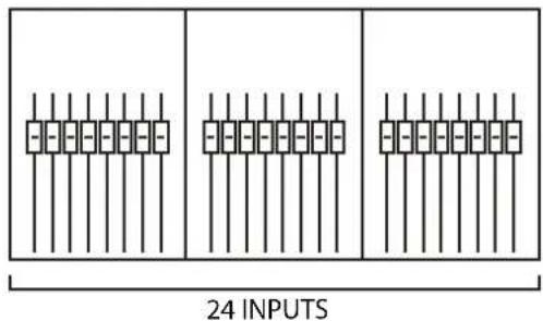
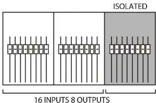
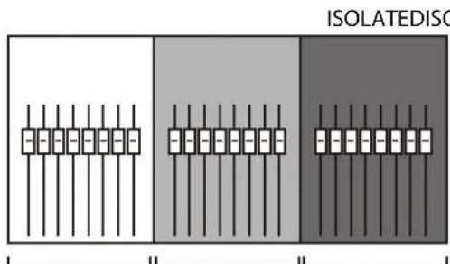
The fader bank section, where 8 faders are provided, can also be used as independent sets of 8 faders or as interlinked sets of 16 or 24 faders. The decision on how to use the 24 controls can be made instantly, letting you operate the M-5000 and its huge mixing engine with optimal efficiency. You can also assign often-used input channels and output buses to the four assignable faders and display them on the top panel at all times.
Organic EL displays offering excellent brightness and visibility are provided above both the fader bank section and the assignable fader section, enabling quick checking of information.
User-assignable section
Assigning frequently used functions to the user-assignable section lets you display important functions on the top panel at all times. This groups together four encoders and eight switches in a compact layout, but you can assign many more functions to this section by switching between three banks.
Included Items
The items included with the M-5000 are as follows. Check to ensure that all are present.
•Power cord
* Be sure to use only the power cord included with the M-5000.
•REAC connector covers (3)
•Ferrite cores (6)
- Quick Start (this document)
• Cover
- Dock cable
• Tablet sheets (2: M-5000 only, 1: M-5000C only)
If any included item is missing, contact the nearest Roland Service Center.
Attaching the Ferrite Cores
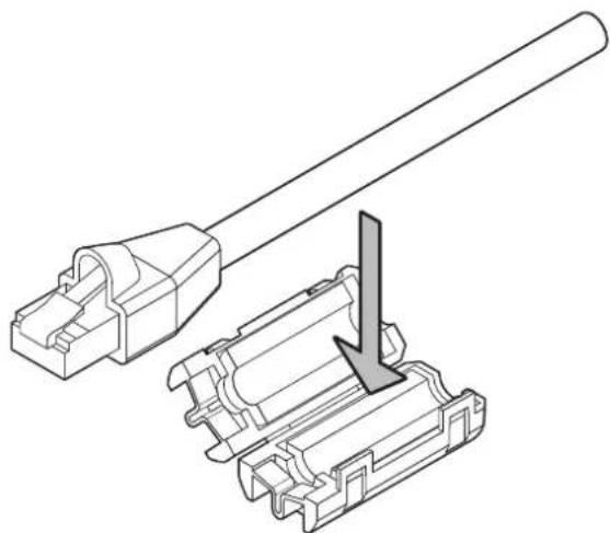
Before you use the M-5000, be sure to attach ferrite cores to any cables connected to the following connectors.
• REAC ports (A, B, SPLIT/BACKUP)
• LAN port
• AES/EBU OUT 1/2, AES/EBU OUT 3/4 jacks
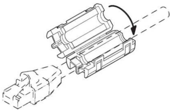
The ferrite cores are intended to counter electromagnetic noise. Leave them attached at all times.
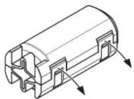
Spread open the tabs and open the ferrite core.
natural_image
Technical line drawing of a mechanical component with internal channels and mounting brackets (no text or symbols)
Attach the ferrite core at a location near the plug base.
natural_image
Technical line drawing of a connector assembly with a cable and internal components (no text or symbols)
Close the ferrite core by pressing down until it snaps into place with an audible click.
natural_image
Technical line drawing of a mechanical assembly with internal components and a directional arrow (no text or symbols)
Connect the plug at the end where the ferrite core is attached to the unit.
Detaching the USB cover (M-5000C only)
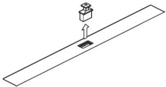
When the M-5000C is shipped, a USB cover is attached to the USB MEMORY connector. Remove the USB cover when using USB flash drive.
natural_image
Simple line drawing of a mechanical component with an upward arrow, no text or symbols present
Detaching the REAC Caps
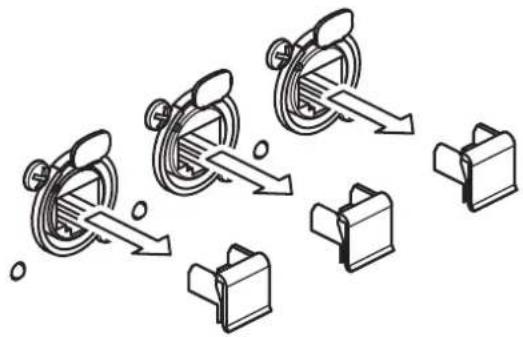
By default, the REAC ports are fitted with REAC caps. Remove these REAC caps when you use the REAC ports. Be careful to not lose the removed REAC caps so you can insert them again when transporting or when the port(s) are not in use.
flowchart
graph TD
    A["Start"] --> B["Add to a device"]
    B --> C["Add to a folder"]
    C --> D["Add to a folder with arrows"]
    D --> E["Add to a folder with arrows"]
    E --> F["End"]
Attaching the REAC Connector Covers
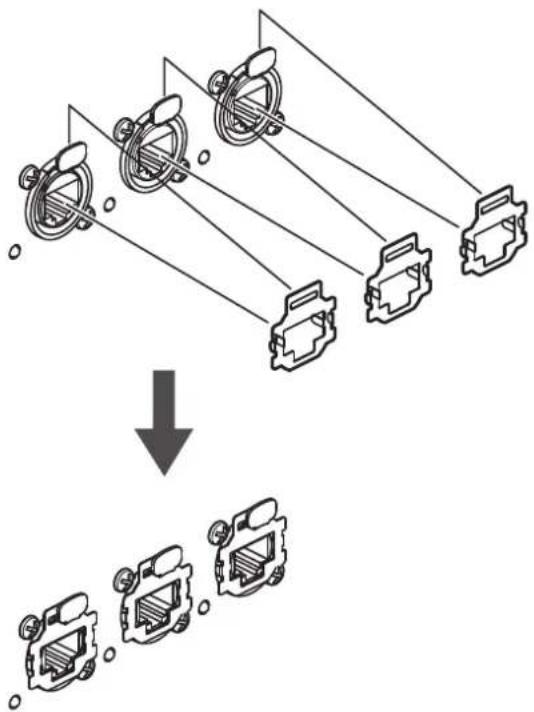
When using commercially available Category 5e Ethernet cables, attach the included REAC connector covers.
flowchart
graph TD
    A["Car Component 1"] --> D["Vehicle"]
    B["Car Component 2"] --> D
    C["Car Component 3"] --> D
    E["Car Component 4"] --> D
    F["Car Component 5"] --> D
    style A fill:#f9f,stroke:#333
    style B fill:#f9f,stroke:#333
    style C fill:#f9f,stroke:#333
    style E fill:#f9f,stroke:#333
    style F fill:#f9f,stroke:#333
MEMO
Remove the REAC connector covers when using EtherCon type REAC cables (SC-W20F, SC-W100S, or W100S-R). Be careful to keep removed REAC connector covers from becoming lost.
Connecting the Power Cord
NOTE
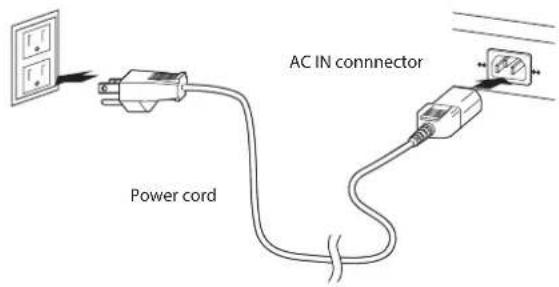
Be sure to use the included power cord for connecting the power supply.
Connect the included power cord to the AC IN connector on the rear panel.
text_image
AC IN connector
Power cord
* The shape of the power cord's plug varies depending on the country.
Using the Power-cord Clamp
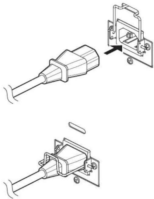
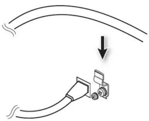
Lower the power-cord clamp as shown in the figure to secure the power cord's plug in place.
natural_image
Technical line drawing of a plug assembly with two views showing internal components (no text or symbols)
natural_image
Technical line drawings of a mechanical device with exploded and assembled views (no text or symbols)
Using the Power-cord Hook
Engage the power cord on the power-cord hook as shown in the figure to secure the power cord in place.
natural_image
Technical line drawing showing two mechanical assembly steps with no visible text or symbols
Connecting Backup Power to the M-5000
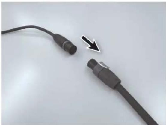
You can connect an adapter cable to the DC OUTPUT plug on an optional S-240P unit, and connect that to the EXT. POWER DC INPUT connector on the M-5000.
For information on the adapter cable used for connection to the DC OUTPUT plug, consult your Roland vendor.
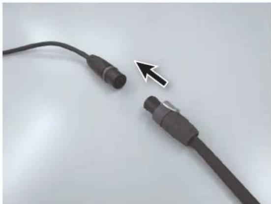
Insert the DC OUTPUT plug on the S-240P into the adapter cable (Speakon end).
natural_image
Close-up of two black cable connectors with a white arrow pointing to one (no text or symbols visible)
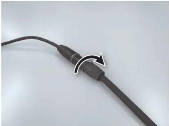
Twist the S-240P's DC OUTPUT plug clockwise until you hear it click.
natural_image
Close-up of a black cable with a curved arrow indicating rotation or adjustment (no text or symbols visible)
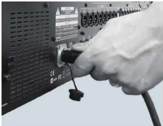
Insert the adapter cable (XLR4 end) into the EXT. POWER DC INPUT connector on the M-5000 until you hear it click.
natural_image
Close-up of a hand inserting a USB into an electronic device panel (no visible text or symbols)
natural_image
Close-up of two black cable connectors with a white arrow pointing to one connector (no text or symbols visible)
natural_image
Close-up of a black cable with a curved arrow indicating rotation or adjustment (no text or symbols visible)
natural_image
Close-up of a hand inserting a black cable into a server rack with visible port labels (no readable text beyond terminal markings)
Disconnecting Backup Power
Follow the steps below to disconnect the external power unit.
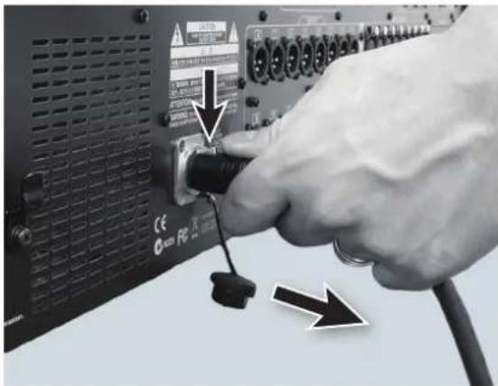
While keeping the lock switch on the adapter cable (XLR4 end) connected to the S-240P depressed, detach the cable from the EXT. POWER DC INPUT connector.
natural_image
Close-up of a hand inserting a black cable into a CD-ROM drive module (no visible text or symbols)
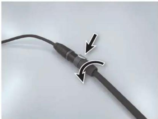
While holding the lock switch on the S-240P's DC OUTPUT plug pulled back, twist counterclockwise.
natural_image
Close-up of a black cable with two arrows indicating clockwise motion (no text or symbols)
Detach the DC OUTPUT plug on the S-240P from the adapter cable (Speakon end).
natural_image
Close-up of two black cable connectors with a white arrow pointing to one (no text or symbols visible)
Turning the Power On and Off
* To prevent malfunction and equipment failure, always turn down the volume, and turn off all the units before making any connections.
* Before turning the unit on/off, always be sure to turn the volume down. Even with the volume turned down, you might hear some sound when switching the unit on/off. However, this is normal and does not indicate a malfunction.
Turning the Power On
* Once everything is properly connecte be sure to follow the procedure below to turn on their power. If you turn on equipment in the wrong order, you risk causing malfunction or equipment failure.
Turn on the power to any equipment connected to audio inputs on the M-5000 or on any input/output units (S-2416, S-4000S, or the like) connected to the M-5000.
Turn on the [POWER] switch on the M-5000.
* This unit is equipped with a protection circuit. A brief interval (a few seconds) after turning the unit on is required before it will operate normally.
* When restarting the unit with the expansion interface installed, wait for about one second before you turn on the power.
Turn on the power to the external power unit connected to the EXT. POWER DC INPUT connector on the M-5000.
Turn on the power to the input/output units.
Turn on the power to any equipment connected to audio output on the M-5000 or on any input/output units.
Turning the Power Off
Go to the MUTE GROUP MASTER window and tap to mute audio output on the M-5000 and on any input/output units (S-2416, S-4000, or the like) connected to the M-5000.
→ "Muting All Outputs" (p. 62)
Turn down the output and turn off the power to any equipment connected to audio output on the M-5000 or on any input/output units.
Turn off the power to the external power unit connected to the EXT. POWER DC INPUT connector on the M-5000.
* If an external power Unit is providing power to the M-5000, the M-5000 will keep operating even if the power switch is in the OFF position.
Turn off the [POWER] switch on the M-5000.
Turn off the power to the input/output units.
Turn off the power to any equipment connected to audio input on the M-5000 or on any input/output units.
* When restarting the unit with the expansion interface installed, wait for about one second before you turn on the power.
* If you need to turn off the power completely, first turn off the unit, then unplug the power cord from the power outlet. Refer to "To completely turn off power to the unit, pull out the plug from the outlet" (p. 4).
text_image
Close-up of a hand inserting a USB cable into an electronic device panel, with Chinese labels and warning arrows indicating installation or repair.
natural_image
Close-up of a black cable with two arrows indicating a curved arrow pointing to a connector (no text or symbols visible)
natural_image
Close-up of two black cable connectors with a white arrow pointing to one connector (no text or symbols visible)
→ "Muting All Outputs" (p. 62)
Replacing the Internal Lithium Battery
The M-5000 has an internal lithium battery that maintains the units's clock function and preserves the mixer settings. If the battery runs down, the clock function and recovery of mixer settings before power-down can fail to operate correctly. If a popup message prompting battery replacement appears after turning on the power, follow the procedure below to replace the battery.
The type of the replacement lithium battery is CR2032. When purchasing a replacement, specify a "CR2032 lithium battery" at an electrical-appliance store or other such point of sale.
* Use only the specified type (model no. CR3032) of lithium batteries.e sure to insert it as directed (to ensure correct polarity).
* Used lithium batteries must be disposed of in compliance with whatever regulations for their safe disposal that may be observed in the region in which you live.
Save the data in the M-5000.
→ "Backing Up All Data in the M-5000" (p. 61)
Turn off the power to the M-5000 and unplug the power cord from the power outlet.
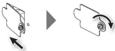
Loosen the mounting screw for the BATTERY slot and detach the BATTERY panel.
natural_image
Diagram showing two mechanical components with curved arrows indicating motion or force, no text or symbols present.
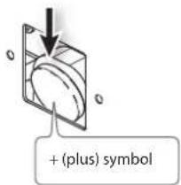
Take out the old battery and replace it with a fresh one.
Press down on the battery to eject it.
Install so that the battery's "+" (plus) symbol faces back toward the front.
text_image
+ (plus) symbol
NOTE
Be careful to avoid cutting your hand on the opening.
Attach the BATTERY panel and secure it in place using the screw loosened in step 3.
natural_image
Diagram showing two mechanical components with directional arrows, no text or symbols present
Turn on the power to the M-5000 and set the date and time.
→ "Setting the Date and Time" (p. 63)
Restoring All Data in the M-5000
→ "Restoring All Data in the M-5000" (p. 62)
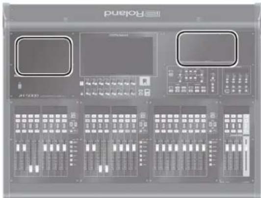
Attaching the Tablet Sheets
Attach the tablet sheets a places shown below. They will protect your tablet / smartphone / PC.
text_image
IE Roland
(000, 14)
M-5000
natural_image
Front view of a Roland audio workstation instrument panel with control knobs and a monitor (no visible text or labels)
M-5000C
→ "Backing Up All Data in the M-5000" (p. 61)
natural_image
Diagram showing two mechanical components with directional arrows, no text or symbols present
→ "Setting the Date and Time" (p. 63)
→ "Restoring All Data in the M-5000" (p. 62)
natural_image
Interior view of a Roland audio workstation with multiple instrument panels and control knobs (no visible text or labels)
M-5000
natural_image
Front view of a Roland audio workstation instrument panel with multiple control knobs and a monitor (no visible text or labels)
M-5000C
Installing an Expansion Interface (Option)
You can expand the M-5000's input and output capabilities by installing a separately available expansion interface into the unit's expansion slot.
For information on the expansion interfaces that can be installed in the M-5000, refer to the Roland website.
* When restarting the unit with the expansion interface installed, wait for about one second before you turn on the power.
Turn off the power to the M-5000 and unplug the power cord from the power outlet.
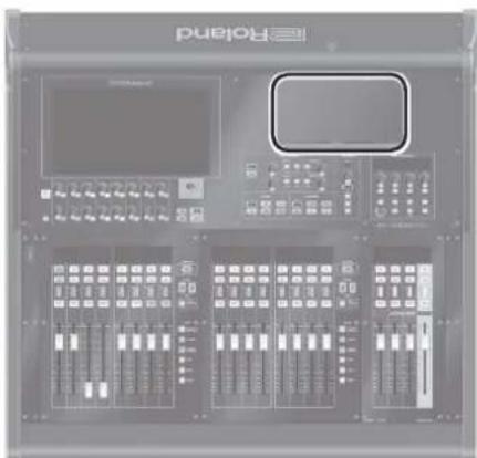
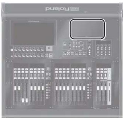
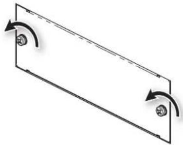
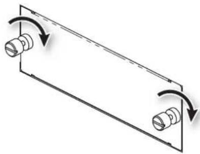
Loosen the mounting screws (2) for the expansion slot specified in the figure, then detach the panel.
natural_image
Pure diagram of a rectangular frame with two circular elements and curved arrows indicating rotation or movement (no text or symbols)
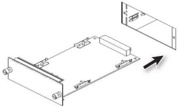
Insert the expansion interface.
natural_image
Technical line drawing of a mechanical assembly with mounting brackets and a separate view showing internal components (no text or symbols)
* To avoid the risk of damage to internal components that can be caused by static electricity, please carefully observe the following whenever you handle the expansion interface.
- Before you touch the expansion interface, always first grasp a metal object (such as a water pipe), so you are sure that any static electricity you might have been carrying has been discharged.
- When handling the expansion interface, grasp it only by the panel or the expansion interface's edges. Avoid touching any of the electronic components or connectors.
- Save the bag in which the expansion interface was originally shipped, and put the expansion interface back into it whenever you need to store or transport it.
Secure using the screws (2) for the expansion slot specified in the figure.
natural_image
Pure mechanical diagram showing two cylindrical components rotating around a rectangular frame with curved arrows indicating rotation (no text or symbols)
* Install only the specified expansion interface. Remove only the specified screws.
* Before installing the expansion interface, you must first always turn off the unit and unplug its power cord.
* Do not touch any of the printed circuit pathways or connection terminals.
* Never use excessive force when installing an expansion interface. If it doesn't fit properly on the first attempt, remove the expansion interface and try again.
* When expansion interface installation is complete, double-check your work.
* Always turn the unit off and unplug the power cord before attempting installation of the expansion interface.
Using the LAN-cable Hook
Engage the LAN cable connected to the LAN port on the LAN-cable hook as shown in the figure to secure it in place. This can help prevent inadvertent detachment of the LAN cable.
natural_image
Diagram showing a cable being inserted into a plug with a magnified inset (no text or symbols)
* Never apply strong force to the LAN cable.
* Never wind (bend) the LAN cable using a coil radius of 25 millimeters or less, or bend the cable sharply enough to kink it.
natural_image
Pure diagram of a rectangular frame with two circular elements and curved arrows indicating rotation or direction (no text or symbols)
natural_image
Technical line drawing of a mechanical assembly with mounting brackets and a separate panel (no text or symbols)
natural_image
Pure diagram of a mechanical component with rotational arrows indicating motion (no text or symbols)
natural_image
Diagram showing cable routing and a camera module with a downward arrow (no text or symbols)
Basic REAC Knowledge
REAC (Roland Ethernet Audio Communication) is Roland's own original digital audio-transmission technology using Ethernet. Its uses protocol independently developed by Roland based on Ethernet technology, and makes possible transmission of 40 input and 40 output channels of 24-bit digital audio at 96 kHz using a single Category 5e Ethernet cable. REAC devices can also easily be interconnected.
Capable of 40 input and 40 output of 24-bit digital audio at 96 kHz
Allows easy device connection using just master, slave, and split settings
Capable of transmission of up to 100 meters over a single Cat 5e cable
Extension of cable length possible using an Ethernet switching hub
Easy signal splitting possible using a switching hub
Extremely short transmission latency between REAC devices (approx. 375 microseconds)
About Cables
Because Category 5e Ethernet cables are used, connecting REAC devices to one another is simple and easy. These Cat 5e Ethernet cables are ordinarily used to make computer network connections.
Ethernet Cable Types
•Crossover cable
The cable's internal wiring crosses over at each RJ45 plug. This means that the connections of the RJ45 plugs at either end of the signal cable are different.
- Straight cable
The cable's internal wiring is arranged identically at each end.
With this unit, you can use either crossover cables or straight cables. For making connections to the REAC ports, we recommend using optionally available REAC cables (SC-W20F, SC-W100S, W100S-R, etc.).
Ethernet Connectors
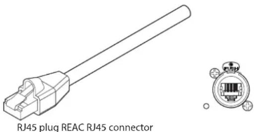
Ethernet cables use RJ45 plugs. REAC devices are provided with an RJ45 connector at REAC port.
text_image
RJ45 plug REAC RJ45 connector
For critically important communication, protecting RJ45 plugs and connectors is vital. In such cases, rugged Neutrik EtherCon plugs are used for the REAC RJ45 plugs.
Using EtherCon RJ45 plugs makes possible the same kind of latch-locked connections as when using XLR plugs.
Neutrik provides EtherCon RJ45 plugs, as well as EtherCon plugs that you can add to or use to modify RJ45 plugs on third-party Ethernet cables.
Important Notes on Handling Ethernet Cables
Never apply strong force to Ethernet cables.
Never wind (bend) an Ethernet cable using a coil radius of 25 millimeters or less, or bend the cable sharply enough to kink it.
Never bind bundled Ethernet cables too tightly.
Never run lengths of multiple Ethernet cables in parallel over long distances.
Keep Ethernet cables away from sources of noise (such as power cords, motors, and fluorescent lights).
Connecting REAC Input/Output Units
This describes how to connect REAC input/output units to the M-5000.
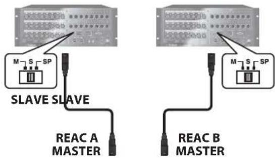
This section shows a typical example of a connection using the S-2416. For connections of greater complexity, refer to the Reference Manual (PDF).
S-2416 S-2416
text_image
M S SP
SLAVE SLAVE
REAC A
MASTER
REAC B
MASTER
natural_image
Front view of a computer audio workstation with multiple audio and audio jackboards (no visible text or labels)
M-5000
CLOCK SOURCE: INTERNAL
The input/output units connected to the REAC A and B ports and the default input/output patchbays on the M-5000 are as follows.
Input port Input channel
REAC A INPUT 1-24 CH 1-24
REAC B INPUT 1-24 CH 25-48
CONSOLE INPUT 1-16 CH 49-64
FX 7 OUTPUT L/R CH 65 (stereo)
FX 8 OUTPUT L/R CH 66 (stereo)
DOCK L/R CH 67 (stereo)
PLAY L/R CH 68 (stereo)
Output port Output bus
REAC A OUTPUT 1-16 AUX 1-16
REAC B OUTPUT 1-8 AUX 17-24
REAC B OUTPUT 9-13 MATRIX 1-5
REAC B OUTPUT 14-16 MAIN L, R, C
CONSOLE OUTPUT 15-16 (M-5000 only)
MONITOR 1 L,R
Important Notes on REAC Connections
REAC connections are designed not to produce noise when hot-swapping (inserting or detaching live lines) is performed. In rare cases, however, noise might occur in the system's audio output. The following two methods can prevent damage due to hot-swapping to speakers or other devices connected to audio outputs.
Make the REAC connection while holding down [MUTE ALL OUTPUTS] on the input/output unit.
Go to the MUTE GROUP MASTER window and use [MUTE ALL OUTPUTS] to mute output, then make the REAC connection.
→ "Muting All Outputs" (p. 62))
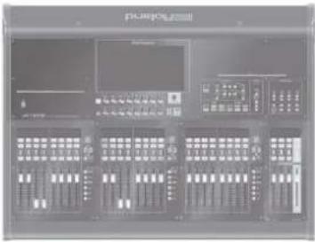
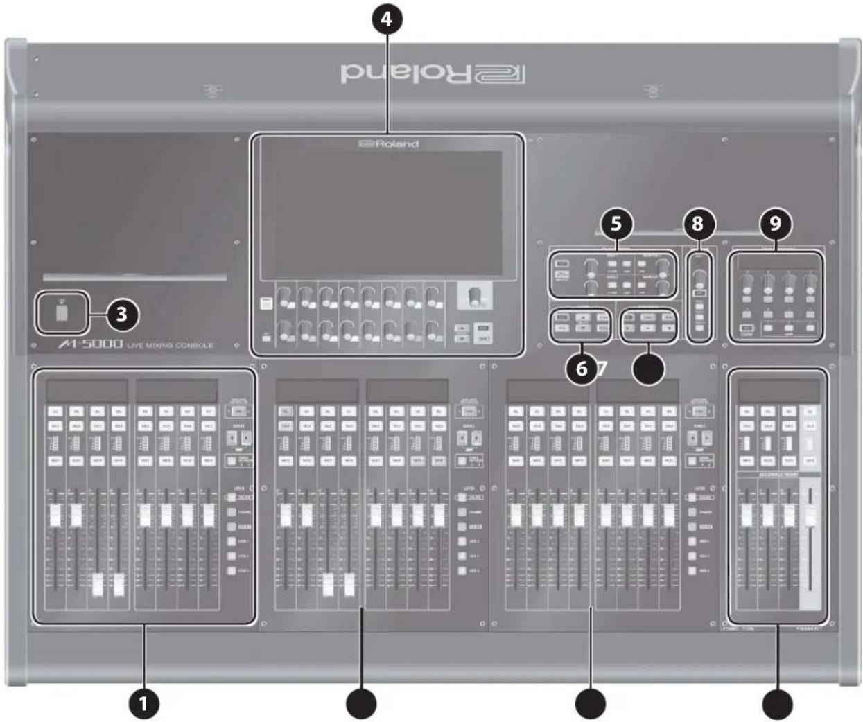
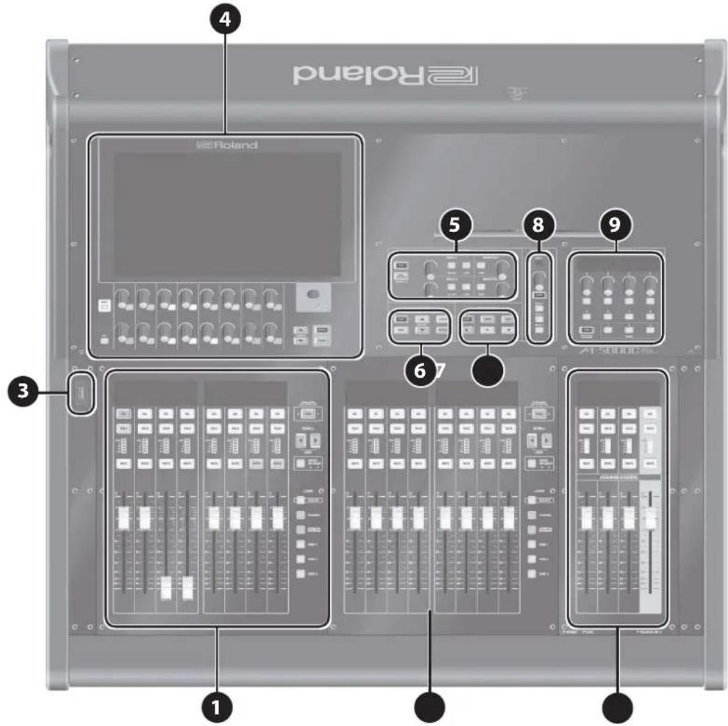
Top Panel
M-5000
text_image
puland
4
Roland
3
A1 5000 LIVE MIXING CONSOLE
5
8
9
6
7
1
M-5000C
text_image
Diagram of a digital audio workstation with labeled components including Poland, 3, 4, 5, 6, and 7.
1 Fader Bank Section
This section is for working with input channels and output buses in sets of eight. You use the layer buttons and scroll buttons to access the desired input channel or output bus.
→ "Fader Bank Section" (p. 30)
2 Assignable Fader Section
This section lets you assign any four input channels or output buses select. This makes it possible to keep important input channels and output buses accessible on the top panel at all times.
→ "Assignable Fader Section" (p. 31)
3 USB MEMORY Connector
This connector is for connecting a USB flash drive.
→ "USB MEMORY Connector" (p. 31)
4 Display Section
This section is for displaying and working with mixer parameters and system settings.
→ "Display Section" (p. 32)
5 Monitor Section
This section is for working with and controlling the monitor buses. "Monitor Section" (p. 33)
6 Scene Section
This section is for working with scene memories.
→ "Scene Section" (p. 34)
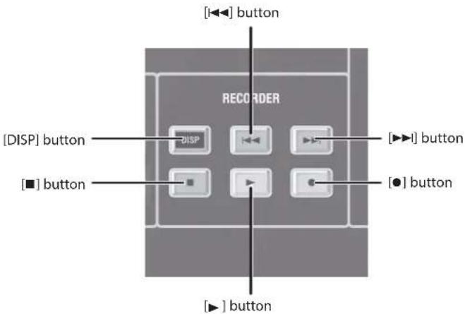
7 Recorder Section
This section is for working with and controlling a USB memory recorder or another external recorder such as the R-1000 48-track recorder.
→ "Recorder Section" (p. 34)
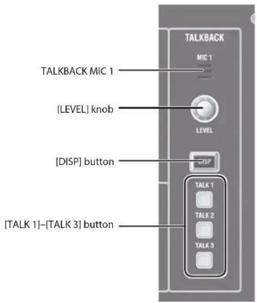
8 Talkback Section
This section is for working with and controlling talkback functions.
→ "Talkback Section" (p. 35)
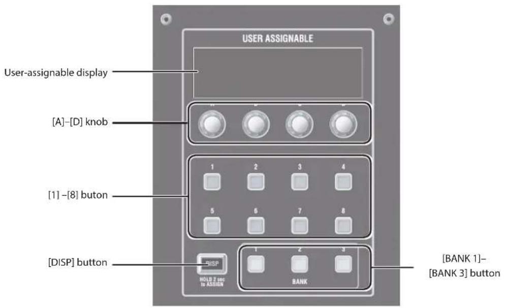
9 User-assignable Section
This section is for assigning and working with parameters of your choosing.
→ "User-assignable Section" (p. 36)
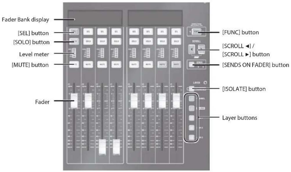
Fader Bank Section
This section is for working with eight input channels or output buses or both. You use layer selection and scrolling to access the desired input channel or output bus.
text_image
Fader Bank display
[SEL] button
[SOLO] button
Level meter
[MUTE] button
Fader
[FUNC] button
[SCROLL ◀] /
[SCROLL ►] button
[SENDS ON FADER] button
[LAYER]
[ISOLATE] button
Layer buttons
Name Description
Fader bank display
This displays information such as the input channel/output bus name and fader value. In the Function mode, it displays menu information such as a list of functions and parameter values.
[SEL] button
This selects the input channel/output bus designating the display target. In the Function mode, it selects the function and sets parameters.
[SOLO] button This turns solo on and off for the input channel/output bus.
Level meter This displays the signal level of the input channel/output bus.
[MUTE] button This turns muting on and off for the input channel/output bus.
Fader This operates the fader for the input channel/output bus.
[FUNC] button This turns the function mode on and off. It flashes when the function mode is on.
[SCROLL ◀] / [SCROLL ▶] button (JUMP)
This scrolls the channel left and right. Pressing [SCROLL ◀] and [SCROLL ▶] at the same time displays the anchor channel where the currently selected Layer in the fader bank display is registered (anchor jump).
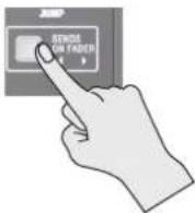
[SENDS ON FADER] button
This turns SENDS ON FADER on and off. It flashes when on. → "Using Faders to Adjust the Send Level to AUX (SENDS ON FADER)" (p. 53)
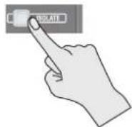
[ISOLATE] button
This turns the isolation of Fader Bank on and off. → "Isolated Banks" (p. 48)
Layer buttons This selects the layer for the Fader Bank section. The button for the selected layer lights up.
Assignable Fader Section
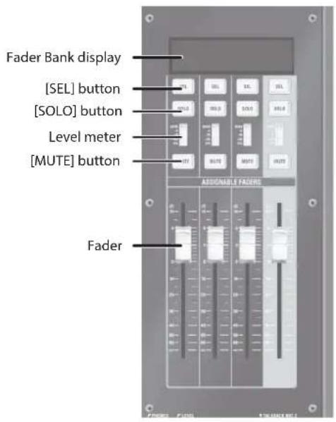
This section lets you assign any four channels of you choosing to the 4 assignable faders. This makes it possible to keep important channels accessible at all times.
For details, refer to the "Assignable Fader Section" in the Reference Manual (PDF).
text_image
Fader Bank display
[SEL] button
[SOLO] button
Level meter
[MUTE] button
Fader
ASSIGNABLE FADERS
Name Description
Fader Bank display
This displays information such as the input channel/output bus name and fader value. In the Function mode, it displays information such as a list of functions and parameter values.
[SEL] button
This selects the input channel/output bus and selects the display target. In the function mode, it selects the function and manipulates parameters.
[SOLO] button This turns solo on and off for the input channel/output bus.
Level meter This displays the signal level of the input channel/output bus.
[MUTE] button This turns muting on and off for the input channel/output bus.
Fader This operates the fader for the input channel/output bus.
USB MEMORY Connector
The M-5000 can use a USB flash drive to store and load a variety of data.
- Project files
→ "Saving a Project File to a USB Flash Drive" (p. 61)
→ "Loading a Project File from a USB Flash Drive" (p. 62)
•Recording and playback of WAV files using a USB flash drive
→ "Recording/Playback to/from a USB Flash Drive" (p. 60)
NOTE
* Never turn off the power or disconnect the USB flash drives when the access lamp of USB flash drives are lit or blinking
* Carefully insert the USB flash drive all the way in—until it is firmly in place.
MEMO
Before using a USB flash drive on this unit, please format the USB flash drives using the built-in format function.. → "Formatting a USB Flash Drive on the M-5000" (p. 62)
Some USB flash drives might not be able to be used on this unit. If an error message appears when formatting as described in "Formatting a USB Flash Drive on the M-5000" (p. 62), it is not possible to use for this USB flash drive on the M-5000.
The M-5000 supports only USB flash drives (USB flash Memory and USB memory). USB Hard Disk and Memory Card Readers are not supported.
USB flash drives do not work via USB hub.
Display Section
This section lets you display and work with mixer parameters, system settings, and other values. For details, refer to the "Operation of the touch display" section in the Reference Manual (PDF).
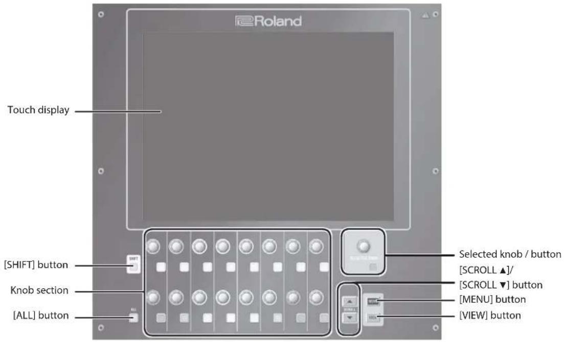
Touch display This displays mixer parameters, settings, and other values. You touch this to manipulate the parameters.
[SHIFT] button This changes the functioning of buttons while depressed.
Knob section
This manipulates the parameter area displayed at the bottom of the touch display.The color or the knob or button changes according to the parameter.
[ALL] button
When this is pressed, the action of the knob or button is applied to the eight channels shown on the touch display.
Selected knob / button
This manipulates the selected parameter on the touch display.The color of the knob or button changes according to the selected parameter.
[SCROLL ▲]/[SCROLL ▼] button
This switches the AUX value selected at the knob-assign area of the HOME screen (p. 50).
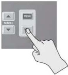
[MENU] button This makes the MENU window appear on the touch display.
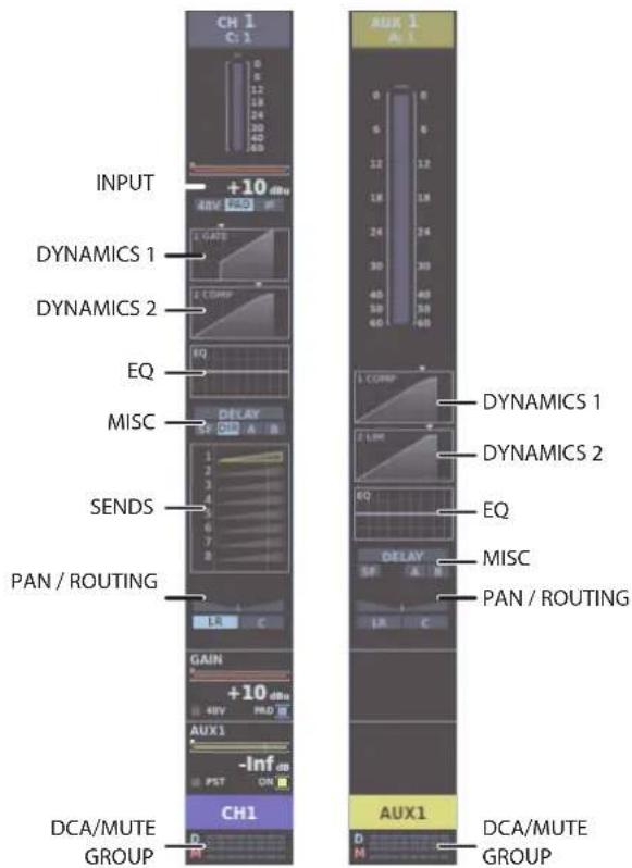
[VIEW] button This switches the appearance of the channel strip on the HOME screen (p. 50).
* Pressing or scraping the surface of the touch display using a pointed object can damage the touch display.
* If the touch display surface becomes dirty, clean by wiping gently using a soft cloth moistened with neutral detergent.
Monitor Section
This section is for working with monitor functions.
This unit is provided with two monitor systems.
The available selections for MONITOR 1 are 5.1, STEREO, and NONE (no assignment), and the available selections for MONITOR 2 are STEREO and NONE (no assignment).
The unit is also provided with two solo systems. These are SOLO 1 for MONITOR 1 and SOLO 2 for MONITOR 2.
The input channel or output bus selected using [SOLO] on the top panel is sent to the monitor.
For details, refer to the "Monitor" section in the Reference Manual (PDF).
text_image
SOLO MONITOR
SOLO 1
MONITOR 1
DISP
TRIM
CLEAR
LAST
DIM
LEVEL
SOLO 2
MONITOR 2
TIM
CLEAR
LAST
DIM
LEVEL
3
4
5
6
7
3
4
5
6
7
Number
Name Description
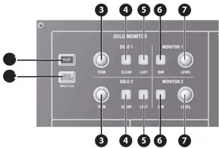
1
[DISP] button This displays the MONITOR window.
2
[SOLO IN PLACE] button
This turns Solo in Place on and off. To turn on Solo in Place, press and hold this button for 2 seconds. It flashes when on.* When Solo in Place is on, a solo signal is sent to the output buses. Note that input channels where solo is turned off are not output.
3
SOLO 1 / SOLO 2 [TRIM] knob This adjusts the level of
SOLO 1 or 2.
4
SOLO 1 / SOLO 2 [CLEAR] button This clears SOLO 1 or 2. It flashes when a channel is currently soloed.
5
SOLO 1 / SOLO 2 [LAST] button This turns the LAST mode on and off for SOLO 1 or 2.
6
MONITOR 1 / MONITOR 2 [DIM] button This turns the dimmer on and off for MONITOR 1 or 2.
7
MONITOR 1 / MONITOR 2 [LEVEL] button This adjusts the level of MONITOR 1 or 2.
Scene Section
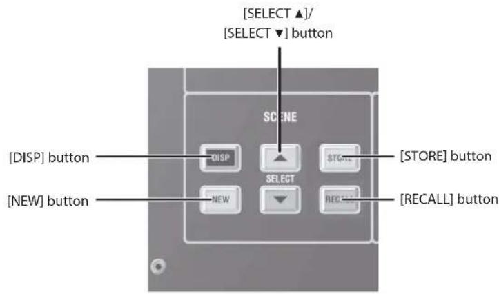
This section is for working with scene memories.
Scene memory is a function that lets you store and recall mixing parameters as "scenes."
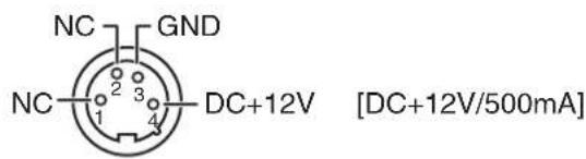
These are XLR-4-31 connectors that supply power to third-party gooseneck lamps.
text_image
NC GND
NC 2 3 4 DC+12V [DC+12V/500mA]
2 POWER Switch
This turns the power on and off.
→ "Turning the Power On and Off" (p. 20)
NOTE
If you need to turn off the power completely, first turn off the unit, then unplug the power cord from the power outlet. Refer to "To completely turn off power to the unit, pull out the plug from the outlet" (p. 4).
3 FOOT SW 1/2 Jacks
These are TRS standard jacks for connecting footswitch pedals.
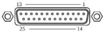
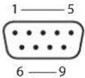
* Pins 7 and 8 are connected inside the M-5000.
* For the M-5000 to function, the three pins RXD, TXD, and GND must be connected as shown in the figure.
* In addition to the owner's manual, RS-232C Reference Manual (PDF) is available as a reference material that covers RS-232C port control.
Download the PDF file from the Roland website.
* RS-232C Reference Manual (PDF) contains the following information.
5 Information on setup
5 Overviews, detailed explanations, and lists of commands
MIDI Connectors
These are connectors for attaching MIDI devices. An IN connector (for reception) and an OUT/THRU connector (for transmission and "thru") are provided.
AES/EBU OUT 1/2, AES/EBU OUT 3/4 Jacks
These jacks output digital audio signals in AES/EBU format (IEC60958-compliant).
AES/EBU IN 1/2, AES/EBU IN 3/4 Jacks
These jacks input digital audio signals in AES/EBU format (IEC60958-compliant).
NOTE
The AES/EBU IN 1/2 and AES/EBU IN 3/4 jacks are not equipped with a sampling-rate converter. Input digital audio signals synchronized to the M-5000's word clock.
DOCK CABLE Connector
This is for connecting an iPad using the dock cable included with the M-5000. This lets you operate the unit remotely and perform audio input and output on 2 channels using the iPad. Charging starts automatically when an iPad is connected.
LAN Port
This is an RJ45 connector for connecting a computer or Wi-Fi router. It lets you operate the M-5000 remotely using a computer or iPad.
LAN-cable Hook
This secures the LAN cable connected to the LAN port. This can help prevent inadvertent detachment of the LAN cable.
0"Using the LAN-cable Hook" (p. 24)
USB WLAN ADAPTER Connector
This is a USB port for connecting a wireless USB adapter (WNA1100-RL, sold separately).
It lets you connect an iPad, computer, or Wi-Fi router.
USB COMPUTER Connector
This is a USB port for connecting a computer.
It lets you operate the M-5000 remotely and perform audio input and output on 16 channels.
REAC Ports (A B, SPLIT/BACKUP)
These are RJ45 connectors for attaching input/output units (such as the S-2416, S-1608, S-0816, and S-4000S) using Cat 5e Ethernet cables.
The unit has two series of REAC ports (A and B). The SPLIT/BACKUP port can split or duplicate the REAC A or B connection.
The REAC SPLIT/BACKUP port is compatible with REAC EMBEDDED POWER, and can supply power to devices compatible with REAC EMBEDDED POWER.
When a REAC device is connected, the system automatically detects whether the device is compatible with REAC EMBEDDED POWER and supplies power if compatible.
Power is not supplied if the device is not compatible with REAC EMBEDDED POWER.
4 Connecteur GP I/O
M-5000
Ordinateur
1: NC
1:
2: RXD
2: RXD
3: TXD
3: TXD
4: NC
4:
5: GND
5: GND
6: NC
6:
7: RTS
7:
8: CTS
8:
9: NC
9:
7 Prises AES/EBU OUT 1/2, AES/EBU OUT 3/4
8 Prises AES/EBU IN 1/2, AES/EBU IN 3/4
WORD CLOCK IN/OUT Connectors
These are connectors for word-clock input and output. To terminate word-clock input at the M-5000, set the 75 ohms switch to ON.
BATTERY Slot
This slot contains a lithium battery that maintains the M-5000's clock function and preserves the mixer settings. If the battery runs down, you need to replace it.
→ "Replacing the Internal Lithium Battery" (p. 22)
Ground Terminal
This terminal is used to connect the M-5000 to an electrical ground.
* Depending on the circumstances of a particular setup, you may experience a discomforting sensation, or perceive that the surface feels gritty to the touch when you touch this device, microphones connected to it, or the metal portions of other objects, such as guitars. This is due to an infinitesimal electrical charge, which is absolutely harmless. However, if you are concerned about this, connect the ground terminal (see figure) with an external ground. When the unit is grounded, a slight hum may occur, depending on the particulars of your installation. If you are unsure of the connection method, contact the nearest Roland Service Center, or an authorized Roland distributor, as listed on the "Information" page. Unsuitable places for connection
•Water pipes (may result in shock or electrocution)
•Gas pipes (may result in fire or explosion)
- Telephone-line ground or lightning rod (may be dangerous in the event of lightning)
AC INPUT Connector, Power-cord Clamp
This connector is for attaching the included power cord. To keep the power cord from being inadvertently disconnected, you use the power-cord clamp to secure the cord in place.
→ "Connecting the Power Cord" (p. 16)
→ "Using the Power-cord Clamp" (p. 16)
→ "To completely turn off power to the unit, pull out the plug from the outlet" (p. 4)
Power-cord Hook
You can use this power cord hook to prevent the power cord from being accidentally disconnected.
→ "Using the Power-cord Hook" (p. 18)
Cooling Fan
This is the fan for cooling the M-5000. When placing the M-5000, be careful not to obstruct the ventilation holes.
EXT. POWER DC INPUT Connector
This connector is for attaching an optional S-240P external power-supply unit to supply backup power to the M-5000.
If an S-240P External Power Supply Unit is providing power to the M-5000, the M-5000 will keep operating even if the power switch is in the OFF position.
* DC INPUT [DC+24V / 6A]
NOTE
To avoid damage or injury, never connect anything to the EXT. POWER DC INPUT jack except the DC output of the S-240P External Power Supply Unit.
OUTPUT 1-16 Connectors (M-5000 only)
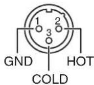
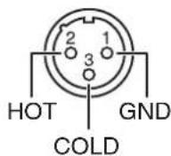
These are male balanced XLR-3-32 output connectors for sending analog audio signals.
* Make connections after first checking the wiring diagrams of other equipment you intend to connect.
OUTPUT 1-8 Connectors (M-5000C only)
These are male balanced XLR-3-32 output connectors for sending analog audio signals.
* Make connections after first checking the wiring diagrams of other equipment you intend to connect.
INPUT 1-16 Connectors
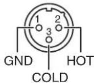
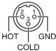
These are female balanced XLR-3-31 input connectors for incoming analog audio signals from microphones and line-level equipment.
* Make connections after first checking the wiring diagrams of other equipment you intend to connect.
+PHANTOM [+48V/14mA]
NOTE
Always turn the phantom power off when connecting any device other than condenser microphones that require phantom power. You risk causing damage if you mistakenly supply phantom power to dynamic microphones, audio playback devices, or other devices that don't require such power. Be sure to check the specifications of any microphone you intend to use by referring to the manual that came with it. (This instrument's phantom power: DC+48 V, 14 mA Max)
EXPANSION SLOT
This slot is for installing an optional expansion interface.
* When restarting the unit with the expansion interface installed, wait for about one second before you turn on the power.
→ "Installing an Expansion Interface (Option)" (p. 24)
14 Ports REAC (A, B, SPLIT/BACKUP)
These are jacks for connecting headphones. You can use them to monitor the MONITOR 1 or MONITOR 2 audio.
Two outputs are provided: miniature stereo phone type and stereo 1/4-inch phone type.
Ensure that the total impedance of both is less than 16 ohms.
2 PHONES LEVEL Knob
This adjusts the output level for headphones connected to the PHONES jacks.
3 TALKBACK MIC 2 Jack
This is a female balanced XLR-3-31 input connector for connecting an external microphone for talkback use.
* Make connections after first checking the wiring diagrams of other equipment you intend to connect.
+PHANTOM [+48V/14mA]
NOTE
Always turn the phantom power off when connecting any device other than condenser microphones that require phantom power. You risk causing damage if you mistakenly supply phantom power to dynamic microphones, audio playback devices, or other devices that don't require such power. Be sure to check the specifications of any microphone you intend to use by referring to the manual that came with it.
(This instrument's phantom power: DC+48 V, 14 mA Max)
25 EXPANSION SLOT
This section describe typical procedures for operating the M-5000. For more information about the operation procedures, refer to the Reference Manual (PDF).
Fader Bank Section
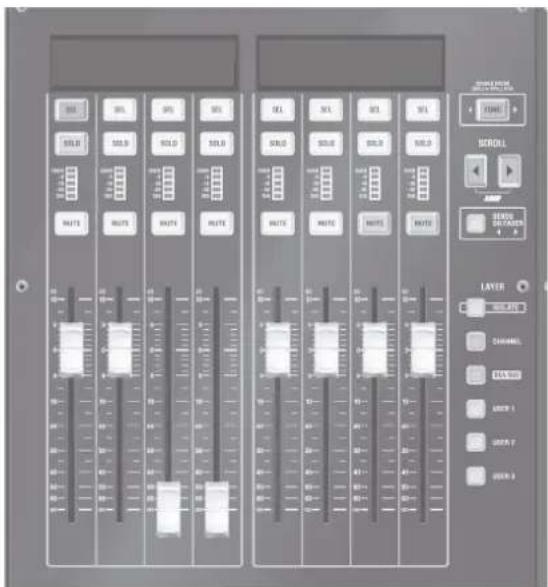
On the M-5000, operations are carried out using groups of eight faders. Each set of eight faders is called a "fader bank."
text_image
SINEMA
100% 100%
SINEMA
100% 100%
SINEMA
100% 100%
SINEMA
100% 100%
SINEMA
100% 100%
SINEMA
100% 100%
SINEMA
100% 100%
SINEMA
100% 100%
SINEMA
100%
SINEMA
100% 100%
SINEMA
100% 100%
SINEMA
100% 100%
SINEMA
100% 100%
SINEMA
100% 100%
SINEMA
100% 100%
SINEMA
100% 100%
SINEMA
100%
The M-5000 is provided with three fader banks and the M-5000C is provided with two fader banks. You can operate the respective fader banks in an interlinked way or independently, enabling you to carry out your intended operations instantly.
Layers
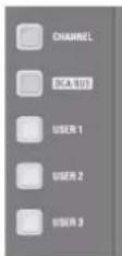
Each fader bank has two basic layers (CHANNEL and DCA/BUS) and three customizable layers (USER 1 through 3) that you can switch between according to purpose.
Scrolling
Pressing the [SCROLL ▶] or [SCROLL ▶] button shifts the channels accessed by the fader bank in the currently selected layer by eight channels at a time.
Basic Operations of Fader Bank Section
Changing Layers
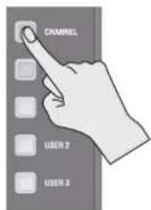
Press a layer button to switch to the desired layer.
text_image
CHANNEL
USER 2
USER 3
If you pressed the button at a "Normal bank" (p. 48), other normal banks also change in an interlinked way.
If an isolated bank has been pressed, only that isolated bank is switched.
Layer button Description
[CHANNEL] This accesses the input-channel layer.
[DCA/BUS]
This accesses the layer of the DCA group master and the output buses (MAIN, SUBGROUP, AUX, MIX-MINUS, and MATRIX).
[USER 1]-[USER 3]
These access user-assigned channels.You can assign up to 64 at a time for each layer.
Scrolling the Channels
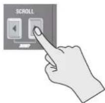
Press the [SCROLL ◀] or [SCROLL ▶] button to scroll the channels.
text_image
SCROLL
The channels assigned to the fader bank section in the selected layer are switched in groups of eight.
MEMO
If you pressed the button at a "Normal bank" (p. 48), other normal banks also change in an interlinked way.
MEMO
Scrolling by one channel at a time when the [SHIFT] button is on.
Anchor Channels
You can mark channels you want to access rapidly in the various layers. These are called "anchor channels."
Specifying anchor channels in the respective layers lets you quickly jump to the desired channel. You can register up to 8 anchor channels in each layer.
MEMO
In the settings, preset anchors are present in the CHANNEL layer at every 24th channel and in the DCA/BUS layer by channel type (DCA, MAIN, SUBGROUP, and the like).
Accessing an Anchor Channel (Anchor Jump)
Press [SCROLL ◀] and [SCROLL ▶] at the same time.
text_image
SCROLL
Anchor channels registered in the currently selected layer are shown on the fader bank display.
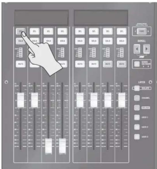
Press the [SEL] button that corresponds to the desired anchor channel.
text_image
Control panel interface with hand pointing to a scroll and layer settings, showing sliders for SEL, RMS, and voltage inputs.
The fader bank scrolls to the location where the anchor channel is displayed in the leftmost fader.
Accessing Adjacent Anchor Channels
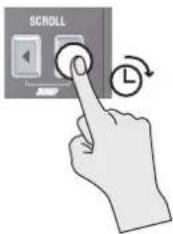
Pressing and holding the [SCROLL ▶] or [SCROLL ▶] button scrolls forward or backward to the anchor channel nearest the currently accessed channel.
text_image
SCROLL
Isolated Banks
A fader bank whose [ISOLATE] button has been turned on is called and "isolated bank." Using isolated banks makes it possible to configure a wide variety of fader layouts, such as arranging a CHANNEL layer and DCA/BUS layer side by side at the same time.
[ISOLATE] Term Description
Off (dark) Normal bank
The bank operates in an interlinked fashion with other normal banks. When layer-switching or scrolling is performed in this normal bank, the earlier or later channel in other normal banks is also accessed.
On (lighted) Isolated bank
This bank is isolated from other fader banks. In an isolated bank, layer-switching and scrolling can be performed independently of other fader banks.
Usage Examples
text_image
24 INPUTS
All banks are set to be normal banks. This allows access to, for example, 24 input-channel faders.
text_image
ISOLATED
16 INPUTS 8 OUTPUTS
One bank is set as an isolated bank. This allows access to, for example, 16 input-channel faders and 8 output-bus faders.
text_image
ISOLATEDISC
Two banks are set as isolated banks. This allows access to, for example, 8 input-channel faders, 8 DCA faders, and 8 other input-channel faders.
8 INPUTS8 INPUTS 8 DCA
(The M-5000 is depicted.)
Isolating a Fader Bank
At the desired fader bank, press the [ISOLATE] button to turn it on (lighted).
The target fader bank is isolated.
Unisolating a Fader Bank
Press the [ISOLATE] button to turn it off (dark).
If one or more other normal banks exist, each switches to the same layer, and the same earlier or later channel is accessed.
Basic Touch Operations
The following four operations are used when working with the touch display.
Tap
Using your fingertip, you press and release an on-screen button, area, or other item.
Double-tap
You make two taps in rapid succession.
Long tap
You touch and hold your fingertip to the touch display for a specific interval before release.
Slide
You drag your fingertip across the touch display while pressing and holding it against a target item.
natural_image
Hand gesture showing finger pressing a button (no text or symbols)
Using Templates to Select a Mixer Configuration
The configuration of the mixing engine in the M-5000 can be changed as you like to suit the desired purpose. This section describes selecting a mixer configuration from templates.
Press the [MENU] button.
Tap , then tap . The MIXER CONFIGURATION window appears.
text_image
MIXER CONFIGURATION
TYPE
INPUT CHANNEL 11
MAIN 2
SUBGROUP 6
AUX 24
MAX-MENUS 6
MATRIX LP 3
HONITOR 1
COMR 1
OSC 2
HEADPHONES 2
DCA 24
MUTE GROUP 8
SOLO 2
REMAINING
RESOURCES: 14
INPUT CHANNEL
1 CHG
2 CHG
3 CHG
4 CHG
5 CHG
6 CHG
7 CHG
8 CHG
9 CHG
10 CHG
11 CHG
12 CHG
13 CHG
14 CHG
TOTAL: 72 1 2 3 4 5 6 7 8 9 10 11 12 13 14
15000000000000000000000000000000000000000000000000000000000000000000000000000000000000000000000000000
TOTAL: 134 REM: 14
IN ON MAIN GRP AUX HMI MTX DTC
TEMPLATE WITH ENTER CANCEL APPLY
Tap .
The TEMPLATE popover appears.
Tap .
Starting point templates for the mixer configurations are available. The Default configuration has the following:
When other window is displayed, to close the window and display the HOME screen, press the [VIEW] button.
This quits the window, attendant popovers, and attendant popups and displays the HOME screen.
(Excludes the MIXER CONFIGURATION window)
text_image
MENU
SCROLL
Access the CH EDIT window
On the HOME screen, tap areas shown below.
text_image
INPUT
DYNAMICS 1
DYNAMICS 2
EQ
MISC
SENDS
PAN / ROUTING
DCA/MUTE GROUP
CH1
DCA/MUTE GROUP
AUX1
DCA/MUTE GROUP
DYNAMICS 1
DYNAMICS 2
EQ
MISC
PAN / ROUTING
+10 dBu
48V 1.50 m
L CAMP
E LWP
S F A B
GAIN
+10 dBu
48V PRD
AUX1
-Inf dB
PST ON
CH1
DCA/MUTE GROUP
Input channel Output bus
The CH EDIT window appears.
For details on how to work with the CH EDIT window, refer to the "CH EDIT Window" section in the Reference Manual (PDF).
Selecting the Source for an Input Channel
Access the CH EDIT window for the desired input channel.
→ "Access the CH EDIT window" (p. 50)
Tap the .
text_image
INPUT tab
CH1
+10 ms
+10 ms
IN
STUDIO
LAVEL INPUT
INPUT MATCH
IN
AST
TB
C: 1
C: 2
LAVEL INPUT
IN
BALANCE
C
Tap .
The SOURCE popover appears.
text_image
SOURCE
1 2 3 4 5 6 7 8
AS AS AS AS AS AS AS AS AS
9 10 11 12 13 14 15 16
AS AS AS AS AS AS AS AS AS AS
AES 1 AES 2 AES 3 AES 4 PLAY 5 PLAY 6 TOM 7 TOM 8
AES AES AES AES AES AS
CATEGORY
C:\LOCAL
C:\CELL
SEQUENCE ASIGN
1 2 3 4 5 6 7
Tap and select the source type.
Select the desired source.
Selecting the Destination for an Output Bus
Access the CH EDIT window for the desired output bus.
→ "Access the CH EDIT window" (p. 50)
Tap the
text_image
OUTPUT tab
CH OUTPUT
AUX1
0.0 mm
OUTLINE SWITCH
OUT
0.0 mm
OUT
0.0 mm
OUT
0.0 mm
OUT
0.0 mm
OUT
0.0 mm
OUT
0.0 mm
OUT
0.0 mm
OUT
0.0 mm
OUT
0.0 mm
OUT
0.0 mm
OUT
0.0 mm
OUT
0.0 mm
OUT
0.0 mm
OUT
0.0 mm
OUT
0.0 mm
IN 12345 12345 12345 12345 12345 12345 12345 12345 12345 12345 12345 12345 12345 12345 12345 12345 12345 12789
IN 12345 12345 12345 12345 12345 12345 12345 12345 12345 12345 12345 12345 12345 12345 12345 12345 0.0 mm
IN 12345 12345 12345 12345 12345 12345 12345 12345 12345 12345 12345 12345 12345 12345 12345 12789
IN 0.0 mm
IN 0.0 mm
IN 0.0 mm
IN 0.0 mm
IN 0.0 mm
IN 0.0 mm
IN 0.0 mm
IN 0.0 mm
IN 0.0 mm
IN 0.0 mm
IN 0.0 mm
IN 0.0 mm
IN 0.0 mm
IN 0.0 mm
IN 0.0 mm
OUT
Access the CH EDIT window for the desired input channel.
→ "Access the CH EDIT window" (p. 50)
Tap the .
text_image
INPUT tab
CH EDIT
CH1
+10 m
STEREO
DAWP INPUT
INPUT SWITCH
IN
ADT
TB
L
C: 1
B
C: 2
CURRENT INPUT
RND
D: DAIN
0.0 m
BALANCE
C
Tap <+48V>.
* Always turn the phantom power off when connecting any device other than condenser microphones that require phantom power. You risk causing damage if you mistakenly supply phantom power to dynamic microphones, audio playback devices, or other devices that don't require such power. Be sure to check the specifications of any microphone you intend to use by referring to the manual that came with it. (This instrument's phantom power: DC+48 V, 14 mA Max)
MEMO
To prevent occurrence of noise, input is briefly muted when phantom power is turned on or off.
Adjusting the Preamp Gain
On the HOME screen, go to the knob-assign area and tap .
text_image
13:42 MULTIPR
00:00:00
KNEI 00:00:00
knob-assign area
text_image
GAIN
D.GAIN
HPF
AUX
DYN 1
AUX
USER
Adjust the preamp gain in the top row of the knob section.
natural_image
Illustration of a hand interacting with a control panel (no text or symbols visible)
Carry out operations using the touch display and knob section.
Using Faders to Adjust the Send Level to AUX (SENDS ON FADER)
Using SENDS ON FADER lets you use faders to adjust the send level to AUX.
MEMO
SENDS ON FADER is applied to all fader banks.
On the HOME screen, go to the knob-assign area and tap .
text_image
AUX TARGET
GAIN D.GAIN HPF
AUX 1 DYN 1
AUX USER
On the SELECT AUX SENDS window, select the AUX that you want to adjust the send levels to.
text_image
SELECT AUX SENDS
AUX3 0147 AUX5 AUX6 0218 AUX9 AUX10
AUX6 AUX11 AUX12 AUX13 AUX14 AUX15 AUX16
AUX11 AUX12 AUX13 AUX14 AUX15 AUX16
SELECT FOLLOWS SAT SOLD EXCEPTION HELP FUNCTION
Press the [SENDS ON FADER] button to turn it on (flashing).
The SENDS ON FADER mode is activated, and you can use faders to adjust the send level to AUX selected in step 2.
Use the faders to adjust the send level.
To change the AUX you are sending to, carry out steps 1 and 2 again.
MEMO
- If an AUX has been assigned to the fader bank, you can change the destination AUX by pressing the corresponding [SEL] button.
Sending to SUBGROUP/MIX-MINUS
This sends an input channel to a SUBGROUP or MIX-MINUS.
MEMO
MIX-MINUS lets you mix a specific channel pulled from MAIN. By default, all input channels are sent with POST FDR (on), with only necessary channels turned off.
Access the CH EDIT window.
→ "Access the CH EDIT window" (p. 50)
Tap the .
text_image
PAN/ROUTING tab
CH EDIT
CH1
0.0m
SUBGROUP
MAIN
L3
C
LED MAX
L
R
PAN
C
K
text_image
FX NAME
DYNAMIC EQ
DATA
DATA
DATA
DATA
DATA
DATA
DATA
DATA
DATA
DATA
DATA
DATA
DATA
DATA
DATA
DATA
DATA
DATA
DATA
DATA
DATA
DATA
DATA
DATA
DATA
DATA
DATA
DATA
DATA
DATA
DATA
DATA
DATA
DATA
DATA
DATA
DATA
DATA
DATA
DATA
DATA
DATA
DATA
DATA
DATA
DATA
DATA
DATA
DATA
DATA
DYNAMIC EQ
DYNAMIC EQ
7. Tap .
The FX EDIT window appears.
text_image
FX EDIT
1
SLE
SL: REVERS
30.0 MHz
TYPE
20
TIME
3.0
TIME OUT
50
STEREO REVERB
TYPE
PLATE
SIZE
20 m
TIME
3.0 s
PRE DELAY
50 ms
REVERB
ISO
REVERB TYPE
BRANCHIAL FILTER
PLATE
OFF
SIZE
TIME
PRE DELAY
EX LEVEL
DIFFUSION
DENSITY
NET
DAY
20 m
3.0
50 ms
-6.0 dB
50
50
0.0 dB
-Inf dB
LF DMP CAIN
LF DMP FREO
MF DMP CAIN
MF DMP FREO
MF CUT FREO
SPREAD
MAX BALANCE
0.0 dB
100 ms
-14.1 dB
10.60k Hz
10.60k Hz
66
C
8. Carry out operations using the touch display and knob section.
Inserting an FX
This inserts an FX at INSERT A or INSERT B on an input channel or output bus.
INSERT A is inserted before dynamics and EQ, and INSERT B is inserted after dynamics and EQ.
flowchart
graph LR
    A["HPF LPF"] --> B["INS A"]
    B --> C["DYN 1 DE"]
    C --> D["DYN 2"]
    D --> E["4-BAND EQ"]
    E --> F["INS B"]
    F --> G["FADER"]
    H["DYN/EQ or EQ/DYN"] --> E
1. Access the CH EDIT window.
→ "Access the CH EDIT window" (p. 50)
2. Tap the .
text_image
MISC tab
CH EDIT
CH1
0.0 mm
0.0 mm
0.0 mm
0.0 mm
0.0 mm
0.0 mm
0.0 mm
0.0 mm
0.0 mm
0.0 mm
0.0 mm
0.0 mm
0.0 mm
0.0 mm
0.0 mm
0.0 mm
0.0 mm
0.0 mm
0.0 mm
0.0 mm
0.0mm
DRLAY
OUT
DIRECT OUT
INSERT A
INSERT B
OUT
OUT
OUT
OUT
OUT
OUT
OUT
OUT
OUT
OUT
OUT
OUT
OUT
OUT
OUT
OUT
OUT
OUT
OUT
OUT
OUT
OUT
OUT
OUT
OUT
OUT
OUT
OUT
OUT
OUT
OUT
OUT
OUT
OUT
OUT
OUT
OUT
OUT
OUT
OUT
OUT
OUT
OUT
OUT
OUT
OUT
OUT
OUT
OUT
OUT
INLET
POST PAGAR
SET ALL CH
POST PAGAR
SET ALL CH
POST PAGAR
SET ALL CH
POST PAGAR
SET ALL CH
POST PAGAR
SET ALL CH
POST PAGAR
SET ALL CH
POST PAGAR
SET ALL CH
POST PAGAR
SET ALL CH
POST PAGAR
SET ALL CH
POST PAGAR
SET ALL CH
POST PAGAR
SET ALL CH
POST PAGAR
SET ALL CH
INSERT A INSERT B
3. Tap or , then select the number of the FX to insert.
flowchart
graph TD
    A["1. DYNAMIC DO"] --> B["2. DYNAMIC DO"]
    B --> C["3. DYNAMIC DO"]
    C --> D["4. DYNAMIC DO"]
    D --> E["5. DYNAMIC DO"]
    E --> F["6. DYNAMIC DO"]
    F --> G["7. DYNAMIC DO"]
    G --> H["8. DYNAMIC DO"]
    H --> I["9. DYNAMIC DO"]
    I --> J["10. DYNAMIC DO"]
    J --> K["11. DYNAMIC DO"]
    K --> L["12. DYNAMIC DO"]
    L --> M["13. DYNAMIC DO"]
    M --> N["14. DYNAMIC DO"]
    N --> O["15. DYNAMIC DO"]
    O --> P["16. DYNAMIC DO"]
    P --> Q["17. DYNAMIC DO"]
    Q --> R["18. DYNAMIC DO"]
    R --> S["19. DYNAMIC DO"]
    S --> T["20. DYNAMIC DO"]
    T --> U["21. DYNAMIC DO"]
    U --> V["22. DYNAMIC DO"]
    V --> W["23. DYNAMIC DO"]
    W --> X["24. DYNAMIC DO"]
    X --> Y["25. DYNAMIC DO"]
    Y --> Z["26. DYNAMIC DO"]
    Z --> AA["27. DYNAMIC DO"]
    AA --> AB["28. DYNAMIC DO"]
MEMO
If the input channel or output bus is stereo, you can make insertions at the following four locations.
•
•
4. Tap INSERT A or INSERT B .
The selected FX is inserted.
5. On the HOME screen, tap .
bar
| Category | Value |
|---|---|
| P.BAY | 0 |
| FX | 0 |
| GEQ | 0 |
The FX RACK window appears.
6. Tap and select the effect library.
text_image
FX NAME FX OVERVIEW
I
SELECT / SELECT
DYNAMIC EQ
DYNAMIC EQ
1 2 3 4
1 2 3 4
DE THURSD
100000
100000
100000
7. Tap .
The FX EDIT window appears.
text_image
FX EDIT
1
SLE REVERB
TYPE
PLATE
SIZE
20 mm
TIME
3.0 s
PRE DELAY
50 mm
STEREO REVERB
TYPE
PLATE
SIZE
20 mm
TIME
3.0 s
PRE DELAY
50 mm
REVERB
EQ
REVERB TYPE
PLATE
BRAJNAL FLOWER
OFF
SET
TIME
PRE DELAY
FE LEVELS
DIFFUSION
OVERTY
WET
DRV
20 ms
3.0
50 ms
-6.0 ns
50
50
LF DMP GAIN
LF DMP FREO
HF DMP GAIN
HF DMP FREO
HI CUT FREO
SPREAD
MIX DELANCE
0.0 mm
100 mm
-14.1 mm
10.60k mm
10.60k mm
66
C
8. Use the touch display and knob section to make detailed adjustments.
Inserting a GEQ
This inserts a GEQ at INSERT A or INSERT B.
INSERT A is inserted before the dynamics and EQ, and INSERT B is inserted after the dynamics and EQ.
flowchart
graph LR
    A["HPF LPF"] --> B["INS A"]
    B --> C["DYN 1 DE"]
    C --> D["DYN 2"]
    D --> E["4-BAND EQ"]
    E --> F["INS B"]
    F --> G["FADER"]
    H["DYN/EQ of EQ/DYN"] --> E
1. Access the CH EDIT window.
→ "Access the CH EDIT window" (p. 50)
2. Tap the .
text_image
MISC tab
CH EDIT
CH1
0.0 mm
0.0 mm
0.0 mm
0.0 mm
0.0 mm
0.0 mm
0.0 mm
0.0 mm
0.0 mm
0.0 mm
0.0 mm
0.0 mm
0.0 mm
0.0 mm
0.0 mm
0.0 mm
0.0 mm
0.0 mm
0.0 mm
0.0 mm
0.0mm
0.0mm
0.0mm
0.0mm
0.0mm
0.0mm
0.0mm
0.0mm
0.0mm
0.0mm
0.0mm
0.0mm
0.0mm
0.0mm
0.0mm
0.0mm
0.0mm
0.0mm
0.0mm
0.0mm
0.0m
0.0m
0.0m
0.0m
0.0m
0.0m
0.0m
0.0m
0.0m
0.0m
0.0m
0.0m
0.0m
0.0m
0.0m
0.0m
0.0m
0.0m
0.0m
0.0m
0.0mm
0.0mm
0.0mm
0.0mm
0.0mm
0.0mm
0.0mm
0.0mm
0.0mm
0.0mm
0.0mm
0.0mm
0.0mm
0.0mm
0.0mm
0.0mm
0.0mm
0.0mm
0.0mm
0.1mm
125mm 325mm 625mm 925mm 125mm 155mm 185mm 215mm 245mm 275mm 315mm 345mm 375mm 415mm 445mm 475mm 515mm 545mm 575mm 615mm 645mm 675mm 715mm 745mm 775mm 815mm 845mm 875mm 915mm 945mm 975mm 1,125mm 1,255mm 1,485mm 1,715mm 2,125mm 2,455mm 2,715mm 3,125mm 3,485mm 3,715mm 4,125mm 4,485mm 4,715mm 5,125mm 5,485mm 5,715mm 6,125mm 6,485mm 6,715mm 7,125mm 7,485mm 7,715mm 8,125mm 8,485mm 8,715mm 9,125mm 9,485mm 9,715mm 1,125mm 1,25mm 1,48mm 1,71mm 2,12mm 2,48mm 2,76mm 3,12mm 3,48mm 3,76mm 4,12mm 4,48mm 4,76mm 5,12mm 5,48mm 6,12cm
INSERT A INSERT B
3. Tap or .
The INSERT popover appears.
4. Tap and select the effect category , then select the number of the GEQ to insert.
If the input channel or output bus is stereo, you can make insertions at the following four locations.
•
6. On the HOME screen, tap .
text_image
00:00:00
REM: 00:00:00
PBAY FX GEO
PEAK/RMS
GR
12 12 12 12
The GEQ window appears.
7. Tap a tab from to , then use the touch display and knob section to make detailed adjustments.
text_image -
Linking Channels
You can link multiple input channels or output buses into up to 12 groups.
The parameters of linked input channels or output buses are set to the same values. You can select the parameters to link.
1. Press the [MENU] button.
2. On the MENU window, tap , then tap .
The CHANNEL LINK window appears.
flowchart
graph TD
    subgraph CHANNEL LINK
        A["LINK"] --> B["LINK1"]
        B --> C["LINK Parameters"]
        C --> D["PREAMP"]
        C --> E["FUTER"]
        C --> F["DYN1"]
        C --> G["DYN2"]
        C --> H["FO"]
        C --> I["DELAY"]
        C --> J["CURRENT OUT"]
        C --> K["SENDS"]
        C --> L["ROUTY"]
        C --> M["PAN"]
        C --> N["MUTE"]
        C --> O["FADER"]
        P["CHANNEL LINK"] --> Q["LINK1"]
        Q --> R["LINK1"]
        R --> S["LINK1"]
        S --> T["LINK1"]
        T --> U["LINK1"]
        U --> V["LINK1"]
        V --> W["LINK1"]
        W --> X["LINK1"]
        X --> Y["LINK1"]
        Y --> Z["LINK1"]
        Z --> AA["LINK1"]
        AA --> AB["LINK1"]
        AB --> AC["LINK1"]
        AC --> AD["LINK1"]
        AD --> AE["LINK1"]
        AE --> AF["LINK1"]
    end
3. Tap a link number from to .
4. Tap .
A popup for setting the link is displayed.
text_image
ASSIGN TO LINK1
Press [SEL] you want to ASSIGN.
CLEAR OR
5. Press the [SEL] button for the input channel or output bus you want to assign to the channel link.
The input channel or output bus is assigned to the channel link.
6. Tap .
7. Select to link.
Making Assignments to DCA/MUTE Groups
In DCA groups, you manipulate the levels of all assigned input channels or output buses at one time.
In MUTE groups, you perform batch muting for the assigned input channels or output buses.
Tap an item from to or to to make the assignment to the DCA group or MUTE group.
Using Talkback
Go to the talkback section on the top panel and press the [DISP] button.
The TALKBACK/OSC window appears.
Tap the tab.
The TALKBACK tab appears.
text_image
TALKBACK / OSC
TALKBACK
OSC
TALKBACK
ASSIGN
1 TBL 1
2 TBL 1
3 TBL 1
MAIN S UFP R AUX E NMR B WEE
TALK INC
TBL 2
HPF SLIPS
-12.00%/m2
TB INC CAIN
-10 ms
80 ms
OB
TB LEVEL
0.0 ms
TALKBACK RETURN
NOT AVAILABLE
TALK MIC
Tap .
text_image
SOURCE
1 2 3 4 5 6 7 8
ADD ADD ADD ADD ADD ADD ADD ADD
9 10 11 12 13 14 15 16
ADD ADD ADD ADD ADD ADD ADD ADD
AIDS 1 AIDS 2 AIDS 3 AIDS 4 PLAY 5 PLAY 6 TIMP 7 TIMP 8
AIDS AIDS AIDS AIDS PLAY 5 TIMP 7 TIMP 8
CATEGORY SEQUENCE ASSIGN
CL LOCAL CLEAR 1 2 4 8 2
Select the input connector.
Use the touch display and knob section to make the settings for the talkback mic.
text_image
TALKBACK / OSC
TALKBACK
OSC
TALKBACK
CASHION
1 148.0
2 150.0
3 155.0
PAIN GWP ADD PAN WEX
TALK HRC
TR Level
-10 dBm
0.0 dBm
90 m
TALKBACK RETURN
NOT AVAILABLE
Tap for TALK 1 to TALK 3.
The DESTINATION popover appears.
text_image
DESTINATION
1.1
MAIN L
1.8
MAIN R
1.6
MAIN C
CATEGORY
MAIN
CLEAR
Select the output destination for TALK 1 to TALK 3.
Press one of the [TALK 1] through [TALK 3] buttons in the talkback section.
Talkback is sent to the selected output bus.
MEMO
The way in which talkback is turned on and off differs depending on how you press the [TALK 1] through [TALK 3] buttons.
When you release the button quickly after pressing it, it operates as a latch to turn talkback on or off with each press.
When depressed for a longer interval before release, it operates as a momentary switch that turns on talkback only while held down.
Using the Oscillators
Go to the talkback section on the top panel and press the [DISP] button.
The TALKBACK/OSC window appears.
Tap the .
The TALKBACK/OSC window OSC tab appears.
text_image
TALKBACK / OSC
TALKBACK
OSC
OSCILLATOR 1
TYPE
FINAL
WHITE
SINE
MUSH
GND
ASSIGN
GND
GND
GND
OSCILLATOR 2
TYPE
FINE
WATER
SIZE
RUCT
GND
GND
ASSIGN
GND
GND
OSC 1 FREQ
1.00k Hz
OSC 1 LEVEL
-Inf dB
OK
OSC 2 FREQ
1.00k Hz
OSC 2 LEVEL
-Inf dB
Select OSCILLATOR TYPE.
PINK Pink noise
WHITE White noise
SINE Sine wave
MULTI 31-band multi-sine wave
Tap .
The DESTINATION popover appears.
text_image
DESTINATION
1 L
PARENT C
2 R
PARENT B
3 C
PARENT C
CATEGORY
MAIN
CLEAR
Select the output destination for the oscillator.
Tap .
Tap /.
Use the selected knob to adjust the level of the oscillator.
The oscillator signal is sent to the selected output bus.
Scene memory
Scene memory is a function that lets you store and recall mixing parameters as "scenes."
Creating New Scenes and Adding Scenes
This adds a new scene following the currently selected scene.
Go to the scene section on the top panel and press the [NEW] button.
text_image
SCENE
DISP
SELECT
NEW
STORE
RECALL
A popup for setting the scene name is displayed.
text_image
Are you sure you want to new?
SCENE 1.00
CANCEL NEW
Specify the scene name, then press the [NEW] button.
A new scene is add immediately following the currently selected scene.
Storing a Scene (by Overwriting)
Go to the scene section on the top panel and press the [SELECT ▲] or [SELECT ▼] button to select the number of the scene you want to store.
Press the [STORE] button.
text_image
SCENE
DISP
SELECT
NEW
SCORE
RECALL
A popup prompting you to confirm the operation is displayed.
text_image
Are you sure you want to store?
SCENE 1.00
CANCEL STORE
Press the [STORE] button.
The scene is stored.
Recalling a Scene
Go to the scene section on the top panel and press the [SELECT ▲] or [SELECT ▼] button to select the number of the scene you want to recall.
Press the [RECALL] button.
text_image
SCENE
DISP
SELECT
NEW
STORE
RECALL
A popup prompting you to confirm the operation is displayed.
Are you sure you want to recall "1.00 SCENE 1"?
CANCEL OK
Press the [RECALL] button.
The scene is recalled.
Recording/Playback to/from a USB Flash Drive
You can record 2-track WAV files to a USB flash drive. You can also play back 2-track WAV files from a USB flash drive.
WAV File Formats
The formats of recordable WAV files are as follows.
The sampling frequency of recorded WAV files is the same as the M-5000's sampling frequency.
Sampling frequency: 96kHz, 48kHz, 44.1kHz
Bit depth: 16bits
Number of channels: 2 channels
The formats of playable WAV files are as follows.
Playback is possible even if the sampling frequency of the WAV file differs from the M-5000's sampling frequency.
Sampling frequency: 96kHz, 48kHz, 44.1kHz
Bit depth: 24bits, 16bits
Number of channels: 2 channels, 1 channel
Recording to a USB Flash Drive
Go to the recorder section on the top panel and press the [DISP] button.
The RECORDER window appears.
text_image
RECORDER
INDLAND/SONGS
NO. NAME LENGTH FORUM ADDITORS
SONG 1 wave 08/20:34 16 MB - 44.1 MHz 11/10/2014
SONG 2 wave 08/20:34 16 MB - 44.1 MHz 11/10/2014
SONG 3 wave 08/20:34 16 MB - 44.1 MHz 11/10/2014
SONG 4 wave 08/20:34 16 MB - 44.1 MHz 11/10/2014
SONG 5 wave 08/20:34 16 MB - 44.1 MHz 11/10/2014
SONG 6 wave 08/20:34 16 MB - 44.1 MHz 11/10/2014
SONG 7 wave 08/20:34 16 MB - 44.1 MHz 11/10/2014
SONG 8 wave 08/20:34 16 MB - 44.1 MHz 11/10/2014
00:00:00
REND GRODIGO
RECE LEVEL
0.0 m
PLAY LEVEL
PLAY MODE
PLAY BACK
CHORD (ON)
CHORD (EUR)
Tap .
The SOURCE popover appears.
text_image
SOURCE
L1
MARCH 1
L2
MARCH 2
L3
MARCH 3
CATEGORY
PLAYS
CLEAR
Select the output bus for recording.
Go to the recorder section on the top panel and press the [●] button.
Go to the recorder section on the top panel and press the [▶] button.
Recording on the selected output bus starts.
Go to the recorder section on the top panel and press the [■] button.
Recording stops.
Playback from a USB Flash Drive
Go to the recorder section on the top panel and press the [DISP] button.
The data in the M-5000 is saved as a project file.
You restore data to the M-5000 by loading a project file from a USB flash drive.
Loading a Project File from a USB Flash Drive
1. Press the [MENU] button.
2. On the MENU window, tap , then tap .
The PROJECT window appears.
text_image
ICON
PROJECT
RDLANDIN 5000/PROJ
FILENAME
SIZE
MODIFIED
Folder 1
81/21/2015
Folder 2
81/21/2015
proj1.mSqj
263 KB
81/21/2015
proj2.mSqj
263 KB
81/21/2015
FORMAT
END
SAVE
3. Move to the folder where you want to load the file.
Moves one level below the current folder.
Moves up one level.
4. Tap for the project file you want to load.
5. Tap .
The LOAD PROJECT window appears.
text_image
LOAD PROJECT (proj1.mSpj)
LOAD SECTION
MOTOR SETTINGS
ECUTE
FADER BANK
VISOR ASSIGNABLE
PROFESSIONAL
RETURN
ACTIVITIES
RETURN
APPROFITATION
ALL
CONFIGURATION
TOTAL: 134
REM: 54
E M OR E MAIN B GAP* B ALS F WM F FREE ETC
CANCEL LOAD
6. Select the section you want to load, then tap .
This mutes all outputs on the M-5000 and input/output units.
Setting the Date and Time
On the HOME screen, tap .
text_image
A B D E
13:22 03/20/2015
00:00:
REM: 00:00:
P.BAY FX GE
PEAK/RMS
GR
0 1 0 0 0
The DATE & TIME window appears.
text_image
DATE & TIME
DATE FORMAT MONTH: DAY / YEAR
DATE 2015 / 3 / 23
TIME 11 : 28 - 29
CANCEL SET
Set the date and time, then tap .
The settings for the date and time are applied.
Factory Reset
This initializes the M-5000, returning it to its factory-default state.
NOTE
Performing initialization causes all data to be lost.
Data that is needed can be saved to a USB flash drive.
→ "Backing Up All Data in the M-5000" (p. 61)
→ "Restoring All Data in the M-5000" (p. 62)
Go to the Display section on the top panel, and while holding down the [MENU] button and [VIEW] button, turn on the power to the M-5000.
Tap .
A popup prompting you to confirm the initialization operation is displayed.
Tap .
Initialization starts.
NOTE
Never turn off the power to the M-5000 before initialization finishes.
The factory reset will require approximately 10 minutes.
When "Factory Initialize completed." appears, tap .
Turn off the power.
Fader Calibration
If the fader positions are no longer aligned with the index markings of the top panel, carry out fader calibration to adjust.
Press the [MENU] button.
On the MENU window, tap , then tap .
The FADER CALIBRATION window appears.
text_image
FADER CALIBRATION
POSITION
+10 dB
0 dB
-20 dB
-10P
CALIBRATE POSITION
1. Touch one of the POSITION buttons.
2. Make sure all fader positions are correct.
3. If necessary, adjust positions, and touch [UPDATE].
Tap an item from <-INF> to <+10dB>.
This moves to the location where all faders are supported.
Adjust the fader that is not aligned with the index markings on the top panel.
The appears.
text_image
FADER CALIBRATION
POSITION
+10 dB
8 dB
-20 dB
-LMP
CALIBRATE POSITION
1. Touch one of the POSITION buttons.
2. Make sure all fader positions are correct.
3. if necessary, adjust positions, and touch [UPDATE].
UPDATE
Tap .
The fader position is adjusted to the specified location.
Main specifications
Roland M-5000/M-5000C: LIVE MIXING CONSOLE
Processing
Mixing Structure
Up to 128 Audio Paths (combination of INPUT CHANNEL, MAIN, SUBGROUP, AUX, MIX-MINUS, MATRIX, MONITOR, COMM, OSC, HEADPHONES)
Inputs
Max 300 (96 kHz), Max 460 (48 kHz / 44.1 kHz)
- CONSOLE: 16
• AES/EBU: 4
- REAC: 40 × 2
• EXPANSION SLOT: 80 x 2 (96 kHz), 160 x 2 (48 kHz / 44.1 kHz)
•USB AUDIO: 16
- DOCK: 2
•USB RECORDER: 2
•FX 1L-8R: 16
•TALKBACK: 2
-OSC:2
Outputs
M-5000: Max 296 (96 kHz), Max 456 (48 kHz / 44.1 kHz)
M-5000C: Max 288 (96 kHz), Max 448 (48 kHz / 44.1 kHz)
•CONSOLE (M-5000): 16
•CONSOLE (M-5000C): 8
• AES/EBU: 4
- REAC: 40 × 2
• EXPANSION SLOT: 80 x 2 (96 kHz), 160 x 2 (48 kHz / 44.1 kHz)
•USB AUDIO: 16
- DOCK: 2
- USB RECORDER: 2
•FX 1L-8R: 16
Internal Processing
- 72 bits (fixed point, bus summing)
Signal Processing
• AD/DA Conversion: 24 bit
•Sampling Rate: 96 kHz, 48 kHz, or 44.1 kHz
Latency
• Network Latency: 1.6 ms (typ.)
•Console Latency: 1.1 ms (typ.)
* Network Latency: Total system latency of audio signal from S-2416 inputs to outputs via M-5000's REAC ports (A or B).
* Console Latency: Total system latency of audio signal from console inputs to console outputs.
* Sampling rate: 96 kHz
* Effect: No insert effects
* When a REAC Splitter S-4000D or a switching hub is used in-line with REAC cables, the network latency will increase by the amount of processing delay introduced by the splitting device itself. The actual delay is dependant upon the specifications of the splitting device, though the maximum delay amount for a single splitting device should be about 200 microseconds.
Connectors
INPUT jacks (1–16): XLR-3-31 type (balanced, phantom power)
•TALKBACK MIC 2 jack: XLR-3-31 type (balanced, phantom power)
•AES/EBU IN jacks (1/2, 3/4): XLR-3-31 type (balanced)
OUTPUT jacks (M-5000: 1–16, M-5000C: 1-8): XLR-3-32 type (balanced)
PHONES 1 jack: Stereo 1/4 inch phone type
• PHONES 2 jack: Stereo miniature phone type
•AES/EBU OUT jacks (1/2, 3/4): XLR-3-32 type
WORD CLOCK connector (IN, OUT): BNC type
•RS-232C connector: DB-9 type
•MIDI connector (OUT/THRU, IN)
•USB port (MEMORY): USB type A
•USB WLAN ADAPTOR port: USB type A
•USB COMPUTER port: USB type B
•LAN port: RJ45 type
DOCK CABLE port: 10-pin mini DIN type
•GP I/O port: DB-25 type
FOOT SWITCH jacks (1, 2): 1/4-inch TRS phone type
LAMP jacks: XLR-4-31 type (M-5000: x 2, M-5000C: x1), LAMP power: DC +12 V/500 mA
EXT.POWER DC IN jack: XLR-4-32 type
* XLR type: 1 GND, 2 HOT, 3 COLD
* Phantom power: DC +48 V (unloaded maximum), 14 mA (maximum load) (All XLR type inputs)
Input/Output Characteristics
Input Impedance
•INPUT jacks (1–16): 7 k ohms
•TALKBACK MIC 2 jack: 4 k ohms (Phantom: ON)
Nominal Input Level (Variable, typ.)
INPUT jacks (1–16): -65 to -10 dBu (Pad: OFF), -45 to +10 dBu (Pad: ON)
•TALKBACK MIC 2 jack: -65 to -10 dBu
•Graphic color LCD 800 x 600 dots (touch screen)
- Graphic organic light emitting display 256 x 64 dots (M-5000: Fader Bank Display x 7, M-5000C: Fader Bank Display x 5, User Assignable Display x 1)
Power Consumption
• 180 W
Dimensions (M-5000)
934 (W) x 725 (D) x 346 (H) mm
•36-13/16 (W) x 28-9/16 (D) x 13-5/8 (H) inches
Dimensions (M-5000C)
740 (W) x 725 (D) x 346 (H) mm
• 29-3/16 (W) x 28-9/16 (D) x 13-5/8 (H) inches
Weight (M-5000)
•36 kg
•79 lbs 6 oz
Weight (M-5000C)
•32 kg
- 70 lbs 9 oz
Operation Temperature
•+5 to +40 degrees Celsius
•+41 to +104 degrees Fahrenheit
Accessories
Owner's manual
•Power cord
Dock cable
REAC connector cover x 3
Ferrite core x 6
Tablet sheet (M-5000: x2, M-5000C: x1)
• Cover
* 0 dBu = 0.775 Vrms
* In the interest of product improvement, the specifications and/or appearance of this unit are subject to change without prior notice.
Dimensions
M-5000
text_image
B31
natural_image
Technical line drawing of an electrical control panel with multiple switches and resistors (no text or labels)
text_image
346
556
725
* Dimensions are shown in millimeters.
M-5000C
text_image
637
text_image
740
text_image
346
556
225
* Dimensions are shown in millimeters.
Memo
This product is intended for use in the following Electromagnetic environments:
E1: residential, E2: commercial and light industrial, E3: urban outdoors,
ex. recording studio which are specified in EN55103-1 and EN55103-2.
For EU Countries
Apparatus containing Lithium batteries
ADVARSEL!
Danger of explosion if battery is incorrectly replaced. Replace only with the same or equivalent type recommended by the manufacturer. Discard used batteries according to the manufacturer's instructions.
WARNING
This equipment has been tested and found to comply with the limits for a Class B digital device, pursuant to Part 15 of the FCC Rules. These limits are designed to provide reasonable protection against harmful interference in a residential installation. This equipment generates, uses, and can radiate radio frequency energy and, if not installed and used in accordance with the instructions, may cause harmful interference to radio communications. However, there is no guarantee that interference will not occur in a particular installation. If this equipment does cause harmful interference to radio or television reception, which can be determined by turning the equipment off and on, the user is encouraged to try to correct the interference by one or more of the following measures:
– Reorient or relocate the receiving antenna.
– Increase the separation between the equipment and receiver.
- Connect the equipment into an outlet on a circuit different from that to which the receiver is connected.
- Consult the dealer or an experienced radio/TV technician for help.
This device complies with Part 15 of the FCC Rules. Operation is subject to the following two conditions:
(1) this device may not cause harmful interference, and
(2) this device must accept any interference received, including interference that may cause undesired operation.
This equipment requires shielded interface cables in order to meet FCC class B limit.
Any unauthorized changes or modifications not expressly approved by the party responsible for compliance could void the user's authority to operate the equipment.
For Canada
CAN ICES-3 (B)/NMB-3 (B)
-For Korea
사용자 안내문
This product contains chemicals known to cause cancer, birth defects and other reproductive harm, including lead.
DECLARATION OF CONFORMITY Compliance Information Statement
Model Name: M-5000/M-5000C
Type of Equipment : Digital Audio Mixer
Responsible Party: Roland Corporation U.S.
Address: 5100S. Eastern Avenue Los Angeles, CA 90040-2938
Telephone : (323) 890-3700
For EU Countries
UK This symbol indicates that in EU countries, this product must be collected separately from household waste, as defined in each region. Products bearing this symbol must not be discarded together with household waste.
About Support and Service
You can get product information and answers to frequently asked questions and download various reference materials from the Roland website. You can download, at no charge, the M-5000 RCS dedicated control software that runs on Macintosh and Windows-based computers.
Other manuals ROLAND
Discover other manuals and user guides for the brand ROLAND
💬 Hi! I'm your manual assistant.I know your ROLAND M-5000C.
How can I help you? (use, settings, error codes, maintenance, explaining a step from the manual, etc.)💡 Examples :
• How do I use it ?
• Error code E3 ?
• How do I clean it ?