GKT 604 ES - Cooker Fors - Free user manual and instructions
Find the device manual for free GKT 604 ES Fors in PDF.

| Product type | Built-in ceramic hob |
| Brand | Fors |
| Model | GKT 604 ES |
| Dimensions (W x D x H) | 580 x 510 x 45 mm |
| Cut-out dimensions | 560 x 490 mm |
| Weight | Approximately 9 kg |
| Power supply | 400V three-phase, 7.1 kW |
| Number of cooking zones | 4 |
| Heater type | HiLight |
| Left front zone | 18 cm / 1.8 kW |
| Left rear zone | 18 cm / 1.8 kW |
| Right rear zone | 21 cm / 2.3 kW |
| Right front zone | 14.5 cm / 1.2 kW |
| Residual heat indicator | Yes, per zone |
| Control | By controls on the built-in oven |
| Surface material | Ceramic glass |
| Cleaning | Special ceramic hob cleaner, scraper |
| Weekly maintenance | Special ceramic hob cleaner |
| Safety device | Residual heat indicator, child safety (supervision required) |
| Customer service | 0 800 55 46 50 (toll-free) |
| Electrical connection | By system plug on oven, earthing mandatory |
Frequently Asked Questions - GKT 604 ES Fors
User questions about GKT 604 ES Fors
0 question about this device. Answer the ones you know or ask your own.
Ask a new question about this device
Download the instructions for your Cooker in PDF format for free! Find your manual GKT 604 ES - Fors and take your electronic device back in hand. On this page are published all the documents necessary for the use of your device. GKT 604 ES by Fors.
USER MANUAL GKT 604 ES Fors
natural_image
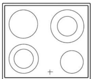
Simple diagram with four circles arranged in a 2x2 grid, one circle marked with a plus sign (no text or symbols)GKT 604 ES GKT 642 ES GKUT 642 ES
natural_image
Simple diagram with four circles arranged in a 2x2 grid, one circle marked with a plus sign (no text or symbols)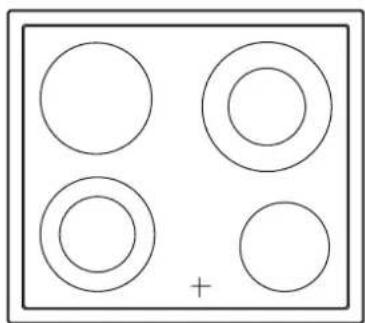
natural_image
Simple diagram with four circles arranged in a 2x2 grid, one circle marked with a plus sign (no text or symbols)D....2
GB 12
F 22
1 32
natural_image
Line drawing of a hand using a tool to connect wires to a circular pipe (no text or symbols)natural_image
Diagram of a mechanical setup with a square component and four circular components above a table, showing directional arrows (no text or symbols)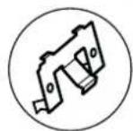
GKT 642 ES
GKUT 642 ES
natural_image
Diagram of a simple setup with a top platform and a square base, no text or symbols present

natural_image
Pure technical diagram showing a wavy line pattern inside a rectangular block with a right-angle cutout (no text or symbols)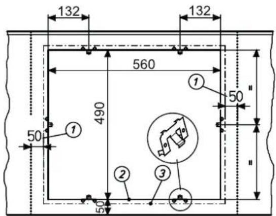

natural_image
Illustration of a hand using a tool to adjust or install a mechanical component (no text or symbols visible)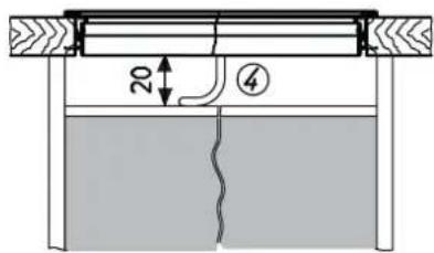
Clipse

Disposing of the packaging
Please ensure the environmentally-friendly disposal of the packaging that came with your appliance. Recycling the packaging material saves on resources and cuts down on waste.
Disposing of old appliances

The symbol on the product or on its packaging indicates that this product may not be treated as household waste. Instead it must be handed over to a collection point for the recycling of electrical and electronic equipment.
By ensuring that this product is disposed of correctly you will help to protect the environment
and human health, which could otherwise be harmed through the inappropriate disposal of this product. For more detailed information about recycling this product, please contact your local city office, your household waste disposal service or the shop where you purchased the product.
Appropriate use
The glass ceramic hob is designed for installation in a worktop. It is connected to the electrical supply of a built-in cooker positioned underneath the hob.
The hob is to be used solely for preparing food in the home and similar areas. Similar areas are:
- The use in stores, offices and other similar working environments
– The use in agricultural enterprises
- The use by customers in hotels, motels and further typical living surroundings
– The use in breakfast pensions
It may not be used for any other purpose and may only be used under supervision.
For your information...
Please read this manual carefully before using your appliance. It contains important information on safety and on how to use and look after your appliance so that it will provide you with many years of reliable service.
Should a fault arise, please first consult the section on "What to do if trouble occurs?". You can often rectify minor problems yourself, without having to call in a service engineer.
Please keep this manual in a safe place and pass it on to new owners for their information and safety.
Contents
Safety Instructions and Warnings 12
Connection and operation.... 12
General information on the hob 13
Concerning persons.... 13
Appliance description.... 14
Operation 15
Hints for cookware and for cooking.... 15
Start of operation 15
Operating the cooking zones 15
Residual heat display.... 15
Cleaning and care 16
Glass ceramic hob 16
Specific soiling 16
What to do if trouble occurs 16
Assembly instructions.... 17
Safety instructions for kitchen unit fitters 17
Installation.... 17
Electrical connection.... 20
Technical data.... 20
Customer service.... 21
Safety Instructions and Warnings
For connection and operation
- The appliances are constructed in accordance with the relevant safety regulations.
-
Connecting the appliances to the mains and repairing and servicing the appliances may only be carried out by a qualified electrician according to currently-valid safety regulations. For your own safety, do not allow anyone other than a qualified service technician to install, service or repair the product.
-
If the mains cable of this appliance is damaged, it has to be replaced by the manufacturer, the Customer Service of the manufacturer or by another qualified person to avoid danger.
- The appliance may not be operated with an external timer or an external telecontrol system.
General information on the hob
- Do not place empty pots and pans on cooking zones which have been switched on. Avoid boiling the pots dry as there is a risk of the pots overheating!
- Take care when using simmering pans as simmering water may dry up unnoticed, resulting in damage to the pot and to the hob for which no liability will be assumed.
• Overheated fats and oils may spontaneously ignite. Always supervise the preparation of food with fats and oils. Never extinguish ignited fats and oils with water! Switch the appliance off and then carefully cover the flame, for example with a blanket or an extinguisher blanket. - The glass ceramic surface of the hob is extremely robust. You should, however, avoid dropping hard objects onto the glass ceramic hob. Sharp objects which fall onto your hob might break it.
- There is a risk of electric shocks if the glass ceramic hob develops fractures, cracks, tears or damage of any other kind. Immediately switch off the appliance. Disconnect the fuse immediately and call Customer Service.
• Take care when working with home appliances! Connecting cables must not come into contact with hot cooking zones. - Risk of fire: never store items on the hob.
-
Do not put aluminium foil or plastic onto the cooking zones. Keep everything which could melt, such as plastics, foil and in particular sugar and sugary foods away from hot cooking zones. Use a special glass scraper to immediately remove any sugar from the ceramic hob (when it is still hot) in order to avoid damaging the hob.
-
Do not place combustible, volatile or heat deformable objects directly underneath the hob.
- Never use the cooking zones to heat up unopened tins of food or packaging made of material compounds. The power supply may cause them to burst!
- Never flambé under the cooker hood - the fat in the filter can ignite!
- Do not allow spilled food to burn repeatedly.
- Never clean the glass ceramic hob with a steam cleaner or similar appliance!
For persons
• These appliances may be used by children aged 8 years and over and by persons with physical, sensory or mental impairments or by persons who lack experience and/or know-how, provided they are supervised or have been instructed in the safe used of the appliance and have understood the risks relating to the appliance. Children may not play with the appliance. Cleaning and maintenance by the user may only be carried out by children when they are supervised.
- The surfaces of the heating and cooking zones become hot during use. Keep small children away at all times.
- Only hob protective grids and hob covers produced by the hob manufacturer or the manufacturers of the hob protective grids and hob covers authorised by the manufacturer in the instructions for use may be used. The use of unsuitable hob protective grids and hob covers may result in accidents.
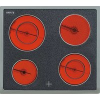
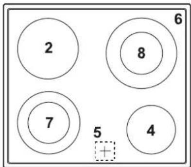
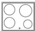
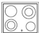
GKT 604 ES
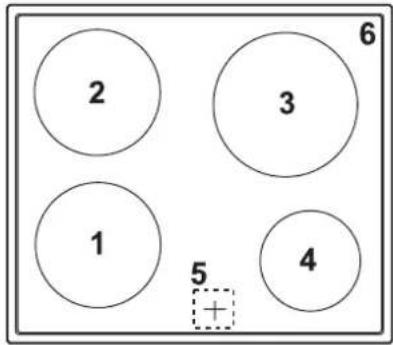
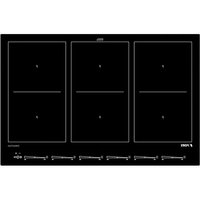
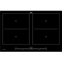
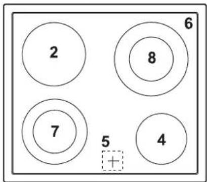
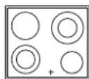
GKT 642 ES
GKUT 642 ES
- Front left cooking zone
- Back left cooking zone
- Back right cooking zone
- Front right cooking zone
- Residual heat display
- Glass ceramic hob
- Front left cooking zone (two-circuit cooking zone)
- Back right cooking zone (two-circuit cooking zone)
Hints for cookware and for cooking
The following are a few useful hints to help you cut your consumption of energy and use your new hob and the cookware efficiently. The principle is: "The better the cookware, the lower the consumption of electricity!"
- The base of good-quality pots and pans is sturdy and level. Uneven pots and pans result in a high consumption of energy and longer cooking times.
- When buying cooking pots, note that it is frequently the diameter of the top of the pot that it indicated. This is usually larger than the base of a pot.
- The base of your cooking pots should be the same size as the cooking zone.
- Pressure cookers are particularly low on energy and time required thanks to the pressure and the fact that they are tightly closed. Short cooking times mean that vitamins are preserved.
- Always make sure that there is sufficient fluid in your pressure cooker since the cooking zone and the cooker may be damaged as a result of overheating if the pressure cooker boils dry.
- The diameter of pots and pans may be larger than the cooking zones but not smaller, since this will result in a loss of heat and spilled food will burn on the cooking zone.
- Use the right pot for the quantity of food you are cooking. A large pot which is hardly filled will use up a lot of energy.
• Always close cooking pots with a suitable lid. - The manufacturer's instructions will also need to be followed when special cookware is used.
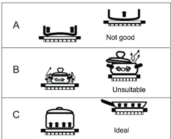
A Cookware base too thin. Becomes uneven when heated up. Higher energy consumption and uneven distribution of heat will result.
B Cookware too large or too small. Energy is wasted if pots are too small or if the lid does not fit properly.
C Good-quality cookware.
Start of operation
- Use a sponge and water with detergent added to wipe lightly over the surface and then dry.
- Switch on all of the cooking zones one after the other for around 3 minutes to dry up any moisture that may be in the heating elements.
Operating the cooking zones
The cooking zones and the dual-circuit cooking zones are activated with the cooking zone switches on the cooker. This is described in the instructions for use of the cooker.
HiLight heating element
Cooking zones with HiLight heating elements start to glow very quickly (see technical data); this is what distinguishes them from standard heating elements. Cooking can be commenced very quickly.
Residual heat display
The glass ceramic hob is equipped with a residual heat display; a lamp has been allocated to each individual cooking zone.
This lamp will light up as soon as the respective cooking zone has heated up to warn against touching the cooking zone unintentionally.
As long as the lamp lights up after the cooking zone has been switched off, the residual heat can be used for melting food or for keeping food warm.
The cooking zone may still be hot when the lamp no longer lights up. Risk of burns!

flowchart
graph TD
    A[" "] --> C[" "]
    B[" "] --> C[" "]
    D[" "] --> C[" "]
    E[" "] --> C[" "]
    C --> F["●"]
    C --> G["●"]
    C --> H["●"]

- Switch the hob off and let it cool down before you clean it.
- Never clean the glass ceramic hob with a steam cleaner or similar appliance!
Glass ceramic hob
Important! Never use aggressive cleaning agents such as rough scouring agents, abrasive saucepan cleaners, rust and stain removers etc.
Cleaning after use
- Always clean the entire hob when it has become soiled. It is recommended that you do so every time the hob is used. Use a damp cloth and a little washing up liquid for cleaning. Then dry the hob with a clean dry cloth to ensure that there is no detergent left on the surface of the hob.
Weekly clean
- Clean the entire hob thoroughly once a week with commercial glass ceramic cleaning agents.
Please follow the manufacturer's instructions carefully.
When applied, the cleaning agent will coat the hob in a protective film which is resistant to water and dirt. All the dirt will remain on the film and can then easily be removed. Then rub the hob dry with a clean cloth. Make sure that no cleaning agent remains on the surface of the hob since this will react aggressively when the hob is heated up and will change the surface.
Specific soiling
Heavy soiling and stains (limescaling and shiny, mother-of-pearl-type stains) can best be removed when the hob is still slightly warm. Use commercial cleaning agents to clean the hob. Proceed as outlined under Item 2.
First soak food which has boiled over with a wet cloth and then remove remaining soiling with a special glass scraper for glass ceramic hobs. Then clean the hob again as described under Item 2.
natural_image
Line drawing of a hand using a tool to draw or install a circular component (no text or symbols)Burnt sugar and melted plastic must be removed immediately, when they are still hot, with a glass scraper. Then clean the hob again as described under Item 2.
Grains of sand which may get onto the hob when you peel potatoes or clean lettuce may scratch the surface of the hob when you move pots around. Make sure that no grains of sand are left on the hob.
Changes in the colour of the hob will not affect the function and the stability of the glass ceramic material. These colour changes are not changes in the material but food residues which were not removed and which have burnt into the surface.
Shiny spots result when the base of the cookware rubs on the surface of the hob, particularly when cookware with an aluminium base or unsuitable cleaning agents are used. They are difficult to remove with standard cleaning agents. You may need to repeat the cleaning process several times. In time, the decoration will wear off and dark stains will appear as a result of using aggressive cleaning agents and faulty pan bases.
What to do if trouble occurs

Interference with and repairs to the appliance by unqualified persons are dangerous as they can result in an electric shock or a short circuit. Do not interfere with or try to repair the appliance; this could cause injury to persons and damage to the appliance. Always have such work done by an expert, e.g. a Customer Service technician.
Please note
If your appliance is faulty, please check whether you can rectify the problem yourself by consulting these instructions for use.
You may be able to rectify some problems yourself. They are described below.
The fuses blow regularly?
- Contact a technical customer service or an electrician!
You can't switch your hob on?
- Has the wiring system (fuse box) in the house blown a fuse?
- Have the cooking zones been switched on with the corresponding switch on the cooker?
- Has the hob been connected to the electric power supply of the cooker?
Does the hob have tears or cracks?
- There is a risk of electric shocks if the glass ceramic hob develops fractures, cracks, tears or damage of any other kind. Immediately switch off the appliance. Disconnect the fuse immediately and call Customer Service.
Safety instructions for kitchen unit fitters
- Veneers, adhesives and plastic surfaces of surrounding furniture must be temperature resistant ( >75^ ). If the veneers and surfaces are not sufficiently heat resistant they can become deformed.
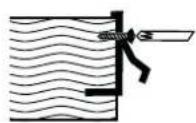
- Ensure that all live connections are safely insulated when installing the hob.
- Cover strips between the wall and the worktop behind the hob which are made of solid wood are permissible as long as minimum clearances in accordance with the installation diagrams are maintained.
- Minimum clearances of the hob cut-out towards the rear are to be maintained in accordance with the installation diagram.
- For installation directly next to a tall cupboard, a safety distance of at least 40 mm must be ensured. The side surface of the tall cupboard should be fitted with heat resistant material. Due to working requirements, however, the distance should be at least 300 mm.
- The clearance between the hob and an extraction hood must be at least as large as that stipulated in the assembly instructions for the cooker hood.
- The packaging materials (plastic foil, polystyrene, nails etc.) must be kept out of reach of children as these parts are potentially dangerous. Small parts can be swallowed and there is a danger of plastic sheeting causing suffocation.
- The hob may only be used once it has been properly installed.
Installation
Important
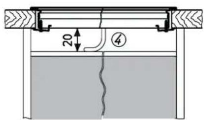
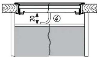
- If the cooking surface is located above furniture parts (side panels, drawers, etc.), then an intermediate shelf must be inserted at a minimum distance of 20 mm in order to prevent accidental contact with the underside of the cooking surface. The intermediate shelf may only be removed with tools.
- To avoid danger of fire, make sure that no combustible objects which could easily catch fire or become deformed on exposure to heat are placed directly next to or above the hob.
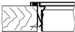
Sealing of the hob
Before installation, correctly insert the sealing unit delivered with the hob.
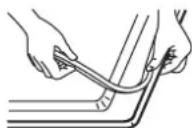
- No liquids may penetrate between the edge of the hob and the worktop or between the hob and the wall and come into contact with any electrical appliances.
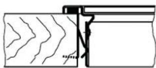
- When installing a hob into an uneven worktop, e.g. with a ceramic or similar covering (tiles etc.), the seal on the hob is to be removed and the seal between the hob and worktop made with plastic sealing materials (putty).
- The hob must under no circumstances be sealed with silicone sealant! This would make it impossible to remove the hob at a later date without damaging it.
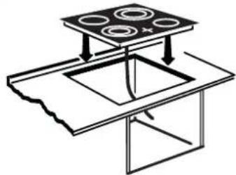
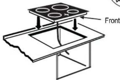
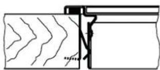
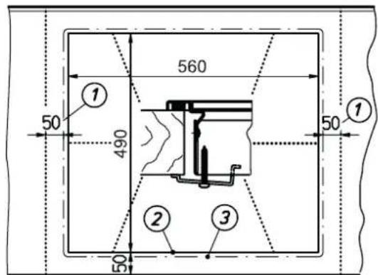
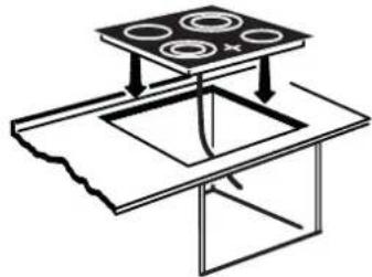
Working surface cut-out
Cut out the worktop recess accurately with a good, straight saw blade or recessing machine. The cut edges should then be sealed so that no moisture can penetrate.
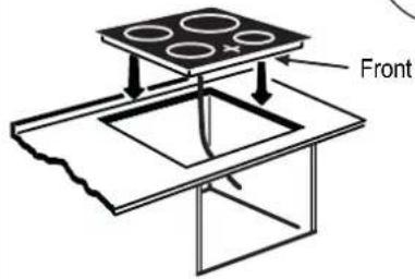
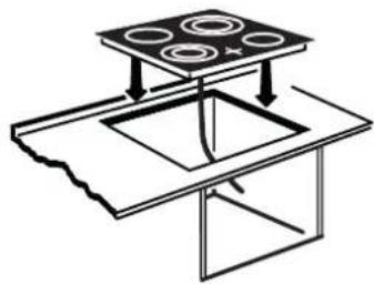
The area is cut out as illustrated.
The glass ceramic hob must have a level and flush bearing. Any distortion may lead to fracture of the glass panel.
Make sure that the sealing of the hob is properly seated.
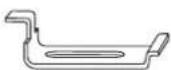
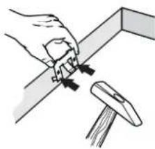
The glass ceramic hob is fastened with clips or with brackets.
Dimensions in mm
GKT 604 ES

GKT 642 ES
GKUT 642 ES
natural_image
Diagram of a laboratory setup with a top platform and a square chamber, showing directional arrows (no text or labels)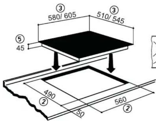
natural_image
Pure technical diagram showing a wavy line pattern inside a rectangular block with a zigzag line and a small rectangular block on the right (no text or symbols)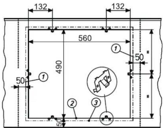
natural_image
Illustration of a hand using a tool to adjust or install a mechanical component (no text or symbols visible)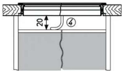
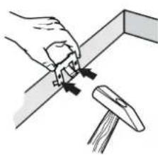
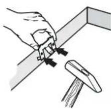
Clips

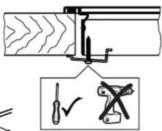
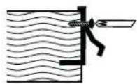
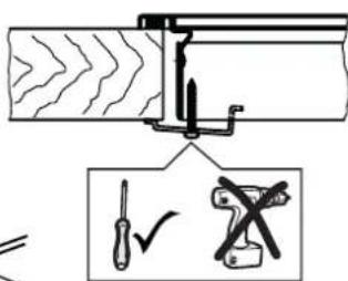
- Drive the clips into the worktop cut-out at the intervals indicated. It is not necessary to adjust the height due to the horizontal stop.
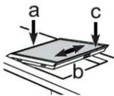
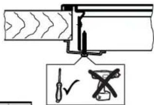
- Important: The horizontal drive of the clips must be flush with the worktop (avoid the risk of fractures).
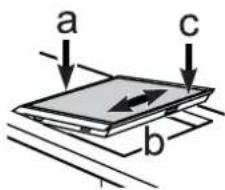
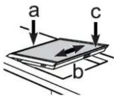
- Position the hob according to the illustration on the left side (a), align it (b) and insert the clips (c).
- Screws may be used to fasten the clips.
Important:
There is a risk of breakage if the hob is canted or subjected to stress during installation!
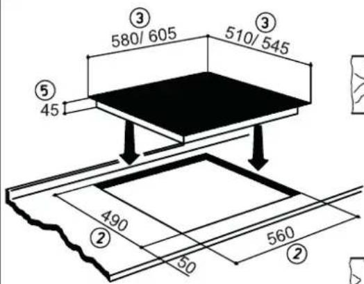
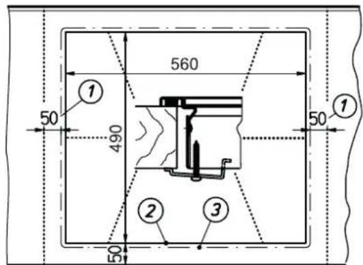
① Minimum distance to adjacent walls
②Cut-out dimension
③Outer dimensions of the hob
GKT 604 580 mm x 510 mm
GKT 642 580 mm x 510 mm
GKUT 642 605 mm x 545 mm
④ Cable routing in rear wall
⑤Installation height
Dimensions in mm
GKT 604 ES

GKT 642 ES
GKUT 642 ES
natural_image
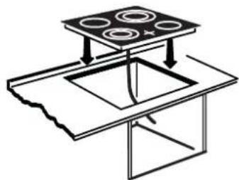
Diagram of a cooking setup with a stove, a square sink, and four circular pots on top (no text or labels)Bracket
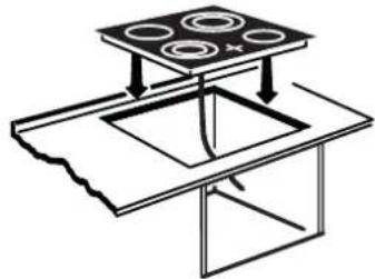
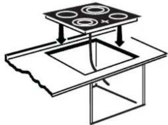
- Insert the hob and align it.
• From the bottom, insert the brackets with screws in the holes provided for fastening the brackets, align the brackets and screw them tight. - Tighten the screws with a hand screw driver only; do not use a battery-operated screw driver.
- In the case of thin worktops make sure that the brackets are correctly positioned.
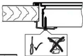
Important:
There is a risk of breakage if the hob is canted or subjected to stress during installation!
① Minimum distance to adjacent walls
②Cut-out dimension
③Outer dimensions of the hob
GKT 604 580 mm x 510 mm
GKT 642 580 mm x 510 mm
GKUT 642 605 mm x 545 mm
④ Cable routing in rear wall
⑤ Installation height
Electrical connection
- The electrical connection must be carried out by a qualified electrician who is authorised to carry out such work!
- Statutory regulations and the connection specifications issued by the local power supply company must be strictly observed.
- When connecting the appliance it must be ensured that there is a device which makes it possible to disconnect it from the mains at all poles with a contact opening width of at least 3 mm. Line-protecting switches, fuses or contactors are suitable cut-out devices.
When connecting and repairing the appliance disconnect it from the electricity supply with one of these devices.
- Any superfluous cable must be removed from the installation area beneath the appliance.
- Full protection against accidental contact must be ensured on installation.
Glass ceramic hob connected to the electrical supply of a cooker
- Connect the unit plug of the hob to the oven located below it. The plug and the sockets have a reverse polarity protection system and/or coloured markings in order to prevent any mix-ups.
Push the plug lightly into the corresponding socket on the oven and allow it to lock into place. - Connect the earthed conductor.
Technical data
GKT 604 ES
Hob dimensions Height/ Width/ Depth. ..... mm 45 x 580 x 510
Installation dimensions Width/ Depth. . . . . . . . . . mm 560 x 490
Cooking zones front left. ....... ∅ cm / kW 18/ 1.8 back left ....... ∅ cm / kW 18/ 1.8 back right ....... ∅ cm / kW 21/ 2.3 front right.... ∅ cm / kW 14.5/ 1
Heating element rated voltage 400V Hob total kW 7.1
GKT 642 ES
Hob dimensions Height/ Width/ Depth. . . . . . mm 45 x 580 x 510
Installation dimensions Width/ Depth. . . . . . . . . mm 560 x 490
Cooking zones front left. ....... ∅ cm / kW 12-18/ 1.7 back left. ....... ∅ cm / kW 18/ 1.8 back right. ....... ∅ cm / kW 12-21/ 2.2 front right. ....... ∅ cm / kW 14.5/ 1.2
Heating element rated voltage 400V Hob total kW 6.9
GKUT 642 ES
Hob dimensions Height/ Width/ Depth. . . . . . mm 45 x 605 x 545
Installation dimensions Width/ Depth. . . . . . . . . . mm 560 x 490
Cooking zones front left. ....... ∅ cm / kW 12-18/ 1.7 back left. ....... ∅ cm / kW 18/ 1.8 back right. ....... ∅ cm / kW 12-21/ 2.2 front right. ....... ∅ cm / kW 14.5/ 1.2
Heating element rated voltage 400V Hob total kW 6.9
All of the cooking zones are equipped with HiLight heating elements.
Customer service

FORS appliances are distinguished by their high quality. Each appliance is checked carefully during the production process, when it is delivered and after installation.
Please read the instructions for use carefully. You will soon see how easy it is to operate the appliance.
You can contact one of the numerous FORS customer service centres if you do run into any problem. You will find an updated list on our website under www.fors.ch
We will be able to help you most quickly if you indicate your address and the details on the nameplate on your hob. The nameplate is clearly visible on the hob.
Factory service free telephone number: 0 800 55 46 50

FORS SERVICE

0 800 55 46 50
For every contact in writing or by telephone please indicate:
- The type and the brand of the appliance
- Product number (see nameplate)
- Date of purchase (see invoice/receipt)
- Type of fault/fault description
- Your exact address
- Your telephone number with your area code, indicating when you are personally available or when you can be reached by telephone.
Glass ceramic hob:
GKT 604 ES....
GKT 642 ES....
GKUT 642 ES
natural_image
Line drawing of a hand using a tool to draw a circular pipe or tube (no text or symbols)natural_image
Diagram of a mechanical setup with a top platform and a square base, showing directional arrows (no text or symbols)
avant
GKT 642 ES
GKUT 642 ES
natural_image
Diagram of a simple setup with a top platform and a square sink, no text or symbols present
natural_image
Pure technical diagram showing a wavy line pattern inside a rectangular block with a zigzag line and a small hatched area (no text or symbols)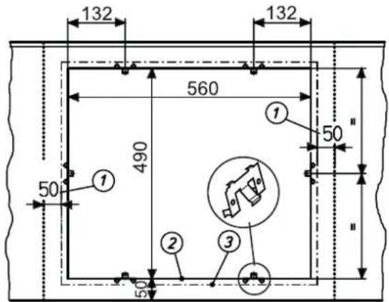

natural_image
Illustration of a hand using a tool to adjust a metal bracket (no text or symbols present)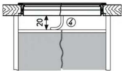
Clips

natural_image
Line drawing of a hand using a tool to draw a circular pipe or tube (no text or symbols)natural_image
Diagram of a mechanical setup with a top platform and a square base, showing internal components (no text or symbols)
GKT 642 ES
GKUT 642 ES
natural_image
Diagram of a simple setup with a top platform and a square sink, no text or symbols present
natural_image
Pure technical diagram showing a wavy line pattern inside a rectangular block with a zigzag line and a small rectangular feature (no text or symbols)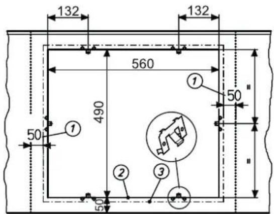
natural_image
Illustration of a hand using a tool to adjust a metal bracket (no text or symbols present)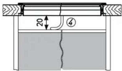

Le clip

natural_image
Diagram of a cooking setup with a top platform and a square sink, showing four circular pots (no text or symbols)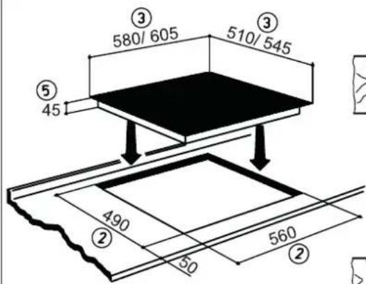
Linguetta