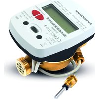
ECC20CA2 - Measuring equipment Fantini Cosmi - Free user manual and instructions
Find the device manual for free ECC20CA2 Fantini Cosmi in PDF.


| Product type | Compact thermal energy meter (heating and cooling) |
| Brand | Fantini Cosmi |
| Model | ECC20CA2 (HYDROCAL-M4) |
| Dimensions (DN15) | 110 × 78 × 73 mm |
| Dimensions (DN20) | 130 × 78 × 76 mm |
| Weight (DN15) | 575 g |
| Weight (DN20) | 700 g |
| Power supply | 2 lithium batteries 3.0 V - 2.7 Ah (non-rechargeable) |
| Battery life | Up to 10 years (depending on configuration and environment) |
| Display | 8-digit LCD + icons |
| Measurement units | J, MJ, GJ, kWh, MWh |
| Temperature range (heating) | +1 °C to +90 °C |
| Temperature range (cooling) | +0.2 °C to +90 °C |
| Minimum temperature difference (heating) | 3 K |
| Minimum temperature difference (cooling) | 0.2 K |
| Nominal flow rate (DN15) | qp = 0.6 m³/h (ratio 50:1) |
| Nominal flow rate (DN20) | qp = 2.5 m³/h (ratio 50:1) |
| Accuracy class | 2 (EN 1434) |
| Protection rating | IP65 |
| Communication interfaces | Wired M-Bus, Wireless M-Bus, LoRaWAN, NFC, IR |
| Pulse inputs | 2 inputs for external meters (external module) |
| Storage conditions | -20 °C to +70 °C, maximum 1 year |
| Operating temperature | +5 °C to +55 °C |
| Standards | MID 2014/32/EU (Module B), EN 1434 |
| Cleaning | Soft damp cloth (water); do not immerse, no alcohol or solvents |
| Battery replacement | Contact the manufacturer; use only original parts |
| Installation | For qualified personnel only; respect the direction of the arrow |
Frequently Asked Questions - ECC20CA2 Fantini Cosmi
User questions about ECC20CA2 Fantini Cosmi
0 question about this device. Answer the ones you know or ask your own.
Ask a new question about this device
Download the instructions for your Measuring equipment in PDF format for free! Find your manual ECC20CA2 - Fantini Cosmi and take your electronic device back in hand. On this page are published all the documents necessary for the use of your device. ECC20CA2 by Fantini Cosmi.
USER MANUAL ECC20CA2 Fantini Cosmi
natural_image
Line drawing of a mechanical device with no visible text or symbolsHYDROCAL-M4 (ECC15CA2 - ECC20CA2)
IT Manuale d'installazione - Contatore di energia termica compatto/
EN Installation manual - Compact thermal energy meter/
FR Manuel d'installation - Compteur d'énergie thermique compact/
ES Manual de instalación - Contador de energía térmica compacto/
DE Installationsanleitung - Kompakter Wärmemengenzähler
EN 1434

1. Introduzione
natural_image
Line drawing of a mechanical device with no visible text or symbolsnatural_image
Line drawing of a mechanical device with no visible text or symbolsnatural_image
Line drawing of a backpack with a cap and handle (no text or symbols)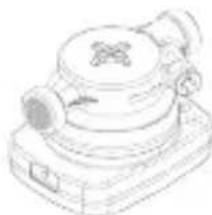
natural_image
Line drawing of a vintage typewriter or typewriter device (no text or symbols visible)The HYDROCAL-M4 is a compact thermal energy meter that measures the energy consumption of heating and cooling systems.
The meter allows to measure the thermal energy passing into a hydraulic circuit used for heating and/or for cooling, it also lets the acquisition through external module, of the volume measured by up to 2 device (water, heat, gas, electricity, HCA) equipped with pulse emitter. The meter can also be connected to a consumption reading network based on the wired M-BUS, Wireless M-BUS and LoraWan network protocols.
WARNING
The first configuration chosen during installation (supply or return pipe) can't be modified!
The top calculation/electronic unit must not be separated from the bottom brass case.
This meter contains potentially dangerous batteries, handle them with caution and do not disperse the components in the environment.
The installation must be carried out by qualified personnel only. The manufacturer doesn't assume any responsibility for improper installation or damages caused by third parties.
STORAGE CONDITIONS
The product must be stored in a dry place at temperatures between -20 ^ and +70 ^ (even during transport). The duration of the storage should not exceed 1 year.
Combined heating or cooling meters are precision devices and must be protected from shock and vibration.
GENERAL INFORMATION
- Before proceeding with the installation and configuration of the product, carefully read the instructions in this manual.
For further technical clarification, please contact Customer Service.
•Installation should be carried out exclusively by qualified personnel.
- The reference standard for the instrument is EN 1434 and Directive 2014/32/E U (Annex MI-004).
- Any tampering of the meter or removal of the seals will void the warranty provided.
- For proper energy accounting, always respect the mounting type prescribed (inlet pipe installation/ return pipe installation).
- The configuration of installation version and unit of measurement can be done with the buttons or an Android device with NFC connectivity.
- Respect the installation point (input or output) of the instrument.
PACKAGING CONTENT: HYDROCAL-M4 device, installation manual, antifraud kit
2. Safety Information
→ Attention: this symbol highlights the instructions to be followed scrupulously for the correct functioning of the combined heat and cooling meter.
Danger: the chapters marked with this symbol contain information that must be followed carefully to avoid dangerous situations. Thermal energy meters are precision devices and must be protected from shock and vibration.
Notes: the notes indicated by this symbol contain tips to keep in mind when using the thermal energy meter.
Read all instructions carefully before proceeding with the installation! Failure to comply with one or more of the procedures contained in the manual can be dangerous and cause damage to property and people. It is recommended to comply with all applicable laws on safety and accident prevention.
| i | Observe national regulations relating to the measurement of cooling. |
| i | Observe the technical requirements relating to the installation of electrical equipment. |
| i | The instrument complies with the requirements of Directive 2014/30/EU of the European Council on electromagnetic compatibility, Directive 2014/35/EU on electrical safety and Directive RED 2014/53/EU. |
| i | If more than one instrument is installed in a unit, the installation conditions must be the same for all instruments to ensure that consumption is billed as possible. |
| → | The warranty and validity of the verification become void if the identification plate or the seals applied to the instrument are removed or damaged. |
| → | Remove the device from the package only at the time of installation to protect it from damage and dirt. |
| ⚠️ | The air transport of active radio devices is prohibited. |
| ⚠️ | Carefully observe the instructions in the data sheet, instruction manual, application notes and lid. Failure to comply with the operating conditions may result in situations of danger and forfeiture of all claims of liability for defects as well as liability based on any guarantees expressly granted. For more information visit the website www.bmeters.com. |
| ⚠️ | Dispose of replaced devices and defective components in accordance with current environmental regulations. |
| ⚠️ | Store out of the reach of children. |
| ⚠️ | Pay attention to the angular or sharp protrusions in the threads, flanges and measuring tube. Therefore, it is recommended to wear protective gloves. |
| ⚠️ | The device shall be used in such a way as to minimize the potential for human contact during normal operation. To avoid the possibility of exceeding radio frequency exposure limits, human proximity to receivers with integrated antenna should not be less than 20 cm (8 inches) during normal operation. |
| ⚠️ | Do not expose the meter to the sun and heat sources. Do not attempt to burn the device. |
| ⚠️ | In case of danger of frost, empty the system and, if necessary, remove the meter. |
| ⚠️ | To clean the device externally use a soft cloth and moistened with water. Do not wash with high-pressure jets or soak the device in water. Avoid contact with oils and solvent. Do not use alcohol or detergents. |
| ⚠️ | Do not damage the casing of the device. In the event of collisions of blunt objects on the front of the display, it can be irreparably damaged and lose the IP65 degree of protection. Install in areas protected against impacts. If the protective casing breaks, contact customer service. |
| ⓘ | The display turns off. To activate it, press the button on the device. The display remains active for 60 seconds. |
| ⓘ | The meter is not suitable for drinking water but is suitable for circulating water in central heating systems. The quality of the water has to be as specified by the CEN/TR 16911 regulation. |
| → | Do not twist, wrap, extend or shorten the cables of the temperature probes and the cable that connects the electronic unit to the part of the lower-case body. |
| → | The thermal energy meter can be installed only in areas protected from frost. |
| → | The thermal energy meter must be protected against pressure shocks in the pipeline. |
| → | Slowly fill the pipe with water at the end of the installation. |
| → | After installing the meter perform a leak test of the system. |
| → | Assemble or disassemble the meter only after depressurization of the system. |
| → | The meter does not have lightning protection. |
| → | Thermal energy meters do not require special protection against electrical interference; however, electromagnetic interference must be avoided. |
| → | If transmission network interfaces are used, especially when cables are routed outside the building, use increased protection against electrical interference. |
| → | Rinse the pipes thoroughly before installing the meter. |
| → | The device must be installed pay attention to matching the direction of the arrow on the meter brass body to the direction of the flow. |
| → | Avoid collecting air bubbles in the meter during the installation process. |
| → | The thermal energy meter must not be subjected to mechanical stress when installed in the pipeline. |
| → | The meter must be installed in such a way as to be protected from all impurities and external contamination. |
| → | Manually and simultaneously screw the device fittings on both sides, and then tighten in opposite directions using a suitable device. |
| → | Remove old seals and clean the sealing surfaces. |
| → | Slightly grease the sealing surfaces (use grease approved by MID Standards). |
| → | Mount only the newly supplied gaskets (gaskets should not get in the pipeline). Seals provided on site must be fit for purpose and comply with local guidelines and directives. B METERS disclaim all liability for consequential damage resulting from the use of third-party gaskets, such as corrosion of sealing surfaces and threads. |
TROUBLESHOOTING
| Problem Cause Solution | ||
| Display off, pressing buttons does not respond | The battery may be damaged or discharged | Inform Customer Service |
| Damaged brass case or leakage | Possible external impact or fall to the ground | Inform Customer Service |
| Lower case brass separated by electronic unit | Tampering by third party or strong external impacts | Inform Customer Service |
| Open and visible electronic unit | Tampering by third party or strong external impacts | Inform Customer Service |
| No consumption is accounted | Tampering by third party, strong external shocks or damage to the flow detection sensor | Inform Customer Service |
| Error 12 always present | Damaged temperature probes | Inform Customer Service |
| Error 18 or 19 always present | Damaged temperature probes or out of system temperatures limits | Inform Customer Service |
| Does not transmit via radio | Failure to pass 5 absolute liters or the batteries may be damaged or discharged | Inform Customer Service |
3. Installation
BEFORE INSTALLATION
EN
Before the thermal energy meter installation make sure that the two ends of the inlet and outlet pipe are perfectly aligned, clean them with the utmost care. Moreover, make sure there is a suitable filter placed at the inlet and that clean and undamaged gaskets are inserted on both sides. The thermal energy meters must be installed as specified by the CEN-TR 13582 regulation. Upstream and downstream the meter install an appropriate water flow interception and regulation devices suitable to allow inspection and maintenance of the meter, control of the water flow and eventual sealing of the system.
→ Attention should be paid to the direction of flow. Install the thermal energy meter so that the passage of water takes place in the direction indicated by the arrow in relief on the brass body and respecting the prescribed position.
To ensure proper measurement, make sure that there is no air inside the pipe and that the flow is clean and free of debris (potentially harmful to the meter turbine).
INSTALLATION
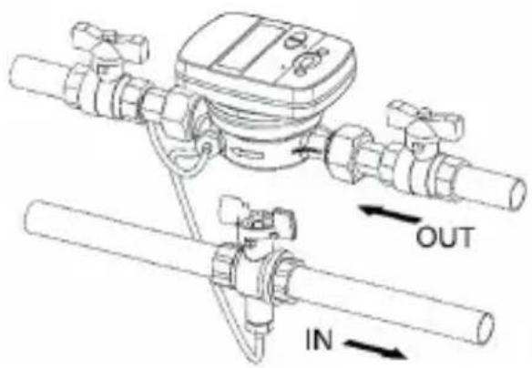
→ It is mandatory to comply with the prescribed type of assembly (return pipe\supply pipe). Always refer to what is on the meter menu 3 level 06. The figure below refers to a standard version of the device installation (mounting on return pipe) and positioned horizontally.
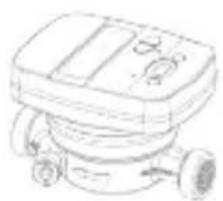
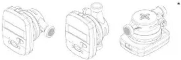
All versions of the thermal energy meter can be installed both horizontally and vertically. For a better performance it is preferable, however, the horizontal installation with the turbine axis perpendicular to the ground and the reading mechanism facing upwards.
natural_image
Line drawing of a mechanical device with no visible text or symbolsIdeal position for a better performance
natural_image
Line drawings of three different types of optical or mechanical devices (no text or symbols)Additional allowed positions
* This position is not suggested for cooling meters and in cases where moisture can enter the electronic casing due to condensation (e.g. during an interruption of the plant in the summer)
TEMPERATURE SENSOR INSTALLATION
The thermal energy meter is equipped with two digital probes that comply with the MID 2014/32/UE directive and the EN1434 standard.
→ For a correct installation, always proceed in compliance with the directives prescribed by current regulations.
In the standard version (e.g mounting on return pipe), the return probe is already incorporated inside the brass case. The supply probe must be installed in a ball valve or in a socket mounted on the flow pipe and complies with the requirements of the sensor itself.
Vice versa, the version for installation on the inlet pipe the probe inserted inside the brass case will be the flow, the return probe will need to be installed in a valve or a socket on the return pipe.
Before installing the ‘free’ probe (the one not inserted in the meter case), it is necessary to intercept the flow (close the ball valve or the appropriate shutters).
INSTALLATION IN A SOCKET BALL VALVE INSTALLATION
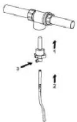
- Screw the socket in the pipe
- Insert the temperature sensor
- Tighten the screw
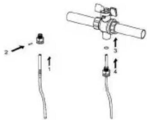
- Insert the probe into the threaded nut
- Insert the closing pin
- Unscrew the valve closing screw, and place the seal
- Insert the probe by screwing it on the thread
→ For a correct temperature measurement, the tip of the probe must be in the center of the pipe. In addition, the axis of the probe must be perpendicular to the pipe axis (see figure).
→ The temperature sensor must be sealed when the installation is complete.
4. Functionality
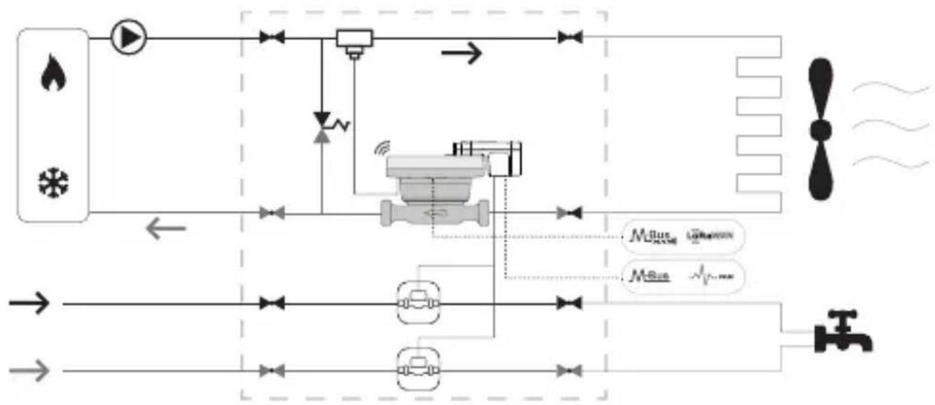
The HYDROCAL-M4 is equipped with dedicated sections for the measurement of thermal energy of a heating/cooling circuit and the volume measurement given by the domestic hot and cold-water meters. The meter is suitable for domestic applications with two-pipe systems, in a thermal power plant or any other compatible application.
In residential systems, usually with two pipes systems, the measurement of thermal energy takes place on a single section both in heating and cooling cycle.
The picture below reports a typical connection diagram (installation on return pipe):
flowchart
graph TD
    A["Valve 1"] --> B["Flow Control Valve"]
    C["Valve 2"] --> B
    D["Valve 3"] --> B
    B --> E["Actuator"]
    E --> F["Water Tap"]
    G["Propeller"] --> H["Pressure Gauge"]
    I["Water Tap"] --> J["Pressure Gauge"]
    K["Pressure Gauge"] --> L["Pressure Gauge"]
    M["Pressure Gauge"] --> N["Pressure Gauge"]
    O["Pressure Gauge"] --> P["Pressure Gauge"]
    Q["Pressure Gauge"] --> R["Pressure Gauge"]
    S["Pressure Gauge"] --> T["Pressure Gauge"]
    U["Pressure Gauge"] --> V["Pressure Gauge"]
    W["Pressure Gauge"] --> X["Pressure Gauge"]
    Y["Pressure Gauge"] --> Z["Pressure Gauge"]
5. Display and buttons
The device is equipped at the front with an LCD and two buttons (T1 and T2), useful for device initialization and readings
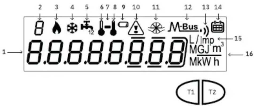
1) Eight-digit numeric field;
2) Single-digit numeric index (menu level);
3) Heating data index;
4) Cooling data index;
5) Circuit 1-2 pulse emitter (external module);
6) Return temperature index;
7) Indicator of sub level presence;
8) Supply temperature index;
9) Battery level indicator;
10) Faults or NFC/IR active communication indicator;
11) Flow presence indicator;
12) M-Bus wired communication data index;
12+13) Wireless M-Bus data index;
13) LoRaWAN communication data index;
14) Historical index;
15) Pulse value index (k);
16) Measurement unit index;
T1) Levels selection button;
T2) Scroll button within the selected level;
6. Commissioning
Premise: before a functional tests, the procedures indicated in this paragraph must be performed for completing the physical installation phases including the connections.

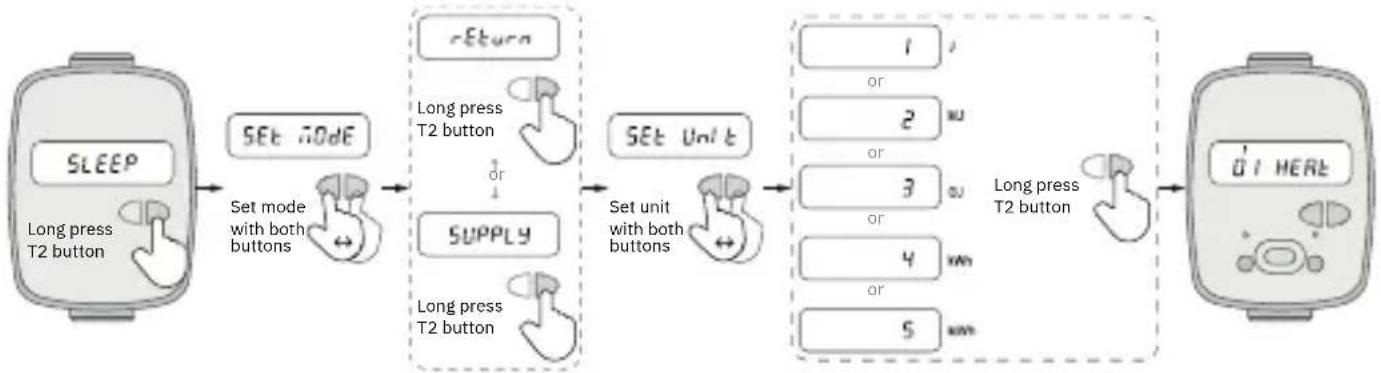
The device is delivered in sleep mode and it must be configured if not requested during the order.

The first configuration chosen during installation (supply or return pipe) can't be modified!
EN
flowchart
graph LR
    A["SLEEP<br>Long press T2 button"] --> B["SET MODE"]
    B --> C["Supply<br>Long press T2 button"]
    C --> D["SET Unit<br>Set unit with both buttons"]
    D --> E["1 or 2 w"]
    D --> F["3 or 4 w"]
    D --> G["5 w"]
    E --> H["0/HEAT"]
    F --> H
    G --> H
If the activation takes place with buttons, the items in the menu will be two:
- Installation version (set Mode): select, through the left/right button (T1/T2), the type of installation (supply or return). Holding down the right button for 3 seconds can temporarily confirm the choice made by switching to level 2 (unit of measurement). If the T1 button is pressed for 3 seconds the device will return to stock mode showing 'SLEEP' on display.
- Units of measurement (set Unit): select through the left/right button (T1/T2), one of the following items: 1 (Joule), 2 (MJ), 3 (GJ), 4 (kWh), 5 (MWh).
Holding down the right button for 3 seconds can temporarily confirm the choice made by switching to level 2 (unit of measurement). If the T1 button is pressed for 3 seconds the device will return to stock mode showing 'set Mode' on display.
NOTE: after confirmation the thermal energy meter will perform the initialization for heating and cooling accounting. The unit of measurement can be changed later via NFC.
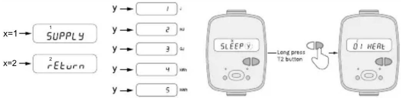
INITIALIZATION (Installation version and measuring unit already configured)

Press T2 button for three seconds to initialize the device, if the installation version and the unit of measurement have already been configured as requested during the order.
flowchart
graph LR
    A["x=1"] --> B["1 SUPPLY"]
    C["x=2"] --> D["2 RETURN"]
    B --> E["y → 1"]
    D --> F["y → 2"]
    D --> G["y → 3"]
    D --> H["y → 4"]
    D --> I["y → 5"]
    E --> J["Long press T2 button"]
    F --> J
    G --> J
    H --> J
    I --> J
    J --> K["0! HERE"]
PROCEDURE FOR COMMISSIONING
1) Check that the mounting position of the thermal energy meter and all electrical wiring are carried out correctly
2) Check if the device is configured, otherwise set the installation version and the unit of measurement
3) Check at level 3 that all configured parameters are correct (heating and cooling data)
4) Check that the thermal energy meter, pulse devices, probes etc. are installed correctly (refer to the specific installation manuals for each product)
5) Start the heating/cooling system:
→ Check the consistency of the reported values (energy and volume)
→ Check in level 2 the instant data
6) Check for errors
7) Apply installation seals. It's recommended to lock the device with a password set through the BMETERING NFC Config android app (downloadable from the Google Play Store).
7. Consultation menu
The consultation menu is divided into 9 levels by a numerical index always visible at the top left of the display. By pressing the T1 button you can choose the desired level, while pressing the T2 button you can view the sublevels of the preset level. After 60 seconds without iteration the display turns off. If no button is pressed within 20 seconds (with the display off) the display cycle will start again from level 1. If a button is pressed within 20 seconds (with the display off) the last level consulted will be displayed. In any level or sublevel, holding down the T1 button for 3 seconds will direct the index to level 1. To access to a sublevels, where present (indicate by the symbol ‘-’), it is necessary to hold down the T2 button for 3 seconds. To return to a main level from a sublevel it’s necessary to hold down the T2 button again for 3 seconds. Each level consists of a brief indication in letters of the data that will be shown after a few seconds in a second screen.
| 1 INDEX INF UM | |||
| 1.01 | HEAT | J,MJ,GJ,kWh,MWh | |
| 1.02 | COOL | J,MJ,GJ,kWh,MWh | |
| 1.03 HEAT m^3 | |||
| 1.04 COOL m^3 | |||
| 1.05 ABSOLUTE m^3 | |||
| 1.06 FORWARD m^3 | |||
| 1.07 REVERSE | m^3 | ||
| 1.08 | IN 1 m^3 | ||
| 1.09 | IN 2 m^3 | ||
| 1.10 | LOST m^3 | ||
| 2 INDEX | INF UM | ||
| 2.01 | POWER H | kW | |
| 2.02 | POWERS | W | |
| 2.03 HEAT | J, Wh | ||
| 2.04 | FLOW | m^3/h | |
| 2.05 | TEMP. SUPPLY | °C | |
| 2.06 | TEMP. RETURN | °C | |
| 2.07 | TEMP.DIFFERENCE | °C | |
| 2.08 | TEMP. AMBIENT. | °C | |
| 3 INDEX INF UM | |||
| 3.01 SERIAL NUMBER | |||
| 3.02 CRC FW | |||
| 3.03 MAIN FW | |||
| 3.04 RADIO FW | |||
| 3.05 DISPLAY FW | |||
| 3.06 | INSTALL TYPE | RETURN, SUPPLY | |
| 3.07 DATE | |||
| 3.08 TIME | |||
| 3.09 UNIT 1,2,3,4,5 | |||
| 3.10 IN 1 ON, OFF | |||
| 3.10.1 PULSE RATE Type of pulse | |||
| 3.10.2 | START VALUE | Type of pulse | |
| 3.10.3 MEDIUM Type of pulse | |||
| 3.11 IN 2 ON, OFF | |||
| 3.11.1 PULSE RATE Type of pulse | |||
| 3.11.2 | START VALUE | Type of pulse | |
| 3.11.3 MEDIUM Type of pulse | |||
| 3.12 MBUS ON, OFF | |||
| 3.12.1 | PRIMARY ADDRESS | ||
| 3.12.2 | SECONDARY ADDRESS | ||
| 3.12.3 | BAUD RATE | BPS | |
| 3.13 | MONTHLY SAVE DAY | ||
| 3.14 | BIWEEKLY SAVE DAY | ||
| 3.15 | DATE SAVE MEM1 | ||
| 3.16 | DATE SAVE MEM2 | ||
| 3.17 | DATE SAVE ANNUAL | ||
| 3.18 | WMBUS TYPE | WB, AMR, AMR CUSTOM, OFF | |
| 3.19 LORAWAN ON, OFF | |||
| 3.20 DISPLAY TEST | |||
| 4 INDEX INF UM | |||
| 4.01 | MEMORY DAY 1 | ||
| 4.01.1 | HEAT | J,MJ,GJ,kWh,MWh | |
| 4.01.2 | COOL | J,MJ,GJ,kWh,MWh | |
| 4.01.3 IN | 1 Type of pulse | ||
| 4.01.4 IN | 2 Type of pulse | ||
| 4.02 | MEMORY DAY 2 | ||
| 4.02.1 | HEAT | J,MJ,GJ,kWh,MWh | |
| 4.02.2 | COOL | J,MJ,GJ,kWh,MWh | |
| 4.02.3 IN | 1 Type of pulse | ||
| 4.02.4 IN | 2 Type of pulse | ||
| 5 INDEX | INF UM | ||
| 5.01 METER LIFE h | |||
| 5.02 | START COUNTING | h | |
| 5.03 HEATING HOURS h | |||
| 5.04 | COOLING HOURS | h | |
| 5.05 NO DELTA HOURS h | |||
| 5.06 | NO ERRORS HOURS h | ||
| 6 INDEX INF UM | |||
| 6.xx* | MONTLY MEMORY 1 | ||
| 6.xx.1 | HEAT | J,MJ,GJ,kWh,MWh | |
| 6.xx.2 | COOL | J,MJ,GJ,kWh,MWh | |
| 6.xx.3 | IN 1 | Type of pulse | |
| 6.xx.4 | IN 2 | Type of pulse | |
| 6.xx.5 | AVG. FLOW TEMP | °C | |
| 6.xx.6 | AVG. RET. TEMP | °C | |
| 6.xx.7 | AVG. CPU TEMP | °C | |
| 6.xx.8 | AVG. HEAT | W | |
| 6.xx.9 | AVG. FLOW | m3/h | |
| 7 INDEX INF UM | |||
| 7.xx* | ANNUAL MEMORY | ||
| 7.xx.1 | HEAT | J,MJ,GJ,kWh,MWh | |
| 7.xx.2 | COOL | J,MJ,GJ,kWh,MWh | |
| 7.xx.3 | IN 1 | Type of pulse | |
| 7.xx.4 | IN 2 | Type of pulse | |
| 7.xx.5 | AVG. FLOW TEMP | °C | |
| 7.xx.6 | AVG. RET. TEMP | °C | |
| 7.xx.7 | AVG. CPU TEMP | °C | |
| 7.xx.8 | AVG. HEAT | W | |
| 7.xx.9 | AVG. FLOW | m3/h | |
| 8 INDEX | INF | UM | |
| 8.01 | Active errors | ||
| 8.xx* | Errors code | ||
| 9 INDEX | INF | UM | |
| 9.xx* | LOG mem errors | ||
| 9.xx.1 | Error data | ||
| 9.xx.2 | Error time | ||
| 9.xx.3 | Error count | ||
* xx equals an incremental index
NOTE: In absence of historical data, levels 6-7-9 will show -- (text).
8. Operating mode – Radio activation
This section describes the radio communication management implemented.
The WMBUS or LoRaWAN radio will activate after the passage of ±5 litres.
Pre-configured radio parameters (WMBus): AMR, 200s, everyday from 0 to 24h, encryption disabled, no historical data, standard package (standard data (heating energy, heating volume, errors, battery value as a percentage).
For more details see the separated WMBUS or LoRaWAN specification document.
RADIO INDICATOR ON DISPLAY
During the JOIN to the network procedure, if the LoRaWAN transmission has been activated, the radio symbol will flash >> quickly on the display (at a period of 1 second) until the device reaches the JOINED state and then remains always active. In the case of a failed JOIN the radio symbol turns off. In the case of WMBUS mode only after switching +/- 5 liters the M-Bus, icon will remain permanently active. In the case of wired M-BUS mode only after switching +/- 5 liters the icon M-Bus will remain permanently active.
9. Errors and faults
When one or more anomalies occur, the thermal energy meter will report the recorded error and show the following icon on the display ⚠️. If the NFC or IR interface is used, the icon will blink for the duration of the communication.
The register of all the anomalies present is shown at level 8 of the consultation menu, where the abbreviation Ern followed by two digits identifies the anomaly.*
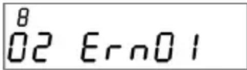
* For the optional alarms that can be activated and further details on the thermal energy meter refer to the complete User manual, available at www.bmeters.com
| Error Name | Description | |
| 03 Qmax Overflow | The error is triggered after the device operates at a flow rate greater than Q4 for 10 consecutive minutes. | |
| 06 Reverse installation | During first installation only, if the absolute counting (forward counter - reverse counter) is equal to 0 and a reverse flow (>10 Liters) is detected, the alarm turns on. | |
| 08-09-10 | Reserved | Inform Customer Service |
| 11 End of battery life | The error is triggered when the remaining battery life is less than 1 year. Permanent error, the icon ☐ is shown on display. | |
| 12 | Probe failure | Failure, short circuit or tampering on supply or return probe(s). |
| 13-14-15-16 | Reserved | Inform Customer Service |
| 17 | Wrong Real Time Clock | Is recorded when a sudden reset of date and time is detected. |
| 18 | Supply Measurement out of range | Measurement of the supply probe over the measuring range. |
| 19 | Return Measurement out of range | Measurement of the return probe over the measuring range. |
| 21 | Delta T non-compliant | The error occurs when for 24 continuous hours without flow and Delta T (temperature difference) >10°C. |
| 25 Display | Overflow | The error is triggered when the energy digits, based on the selected unit, go further the maximum possible display. |
| 26-27 | Reserved | Inform Customer Service |
| 35 MBUS | disconnected | The error is triggered when MBUS communication is not detected for 2 consecutive hours. |
| 36 Wrong module | The error is triggered when the external module has been removed and a second module is mounted. | |
| 37 Module removal | The error is triggered when the module is not detected for 5 consecutive failed communications. | |
| 38 End of battery life module | The error is triggered when the remaining battery life of the external module is less than 1 year. | |
| 39 | Reserved | Inform Customer Service |
| 40 NFC Fraud | The error is triggered when an NFC field is detected for more than some minutes. | |
10. Battery and replacement procedures
The thermal energy meter constantly monitors the status of the battery (maximum life: 10 years*) and signals the imminent discharge by showing the icon on display □. Reporting takes place one year before full discharge. For more details see the separated WMBUS specification document.
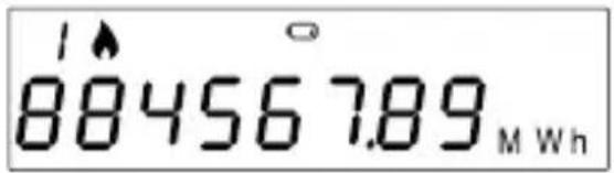
*The battery life strongly depends on the working time window, set during the configuration process, and on the environmental conditions. Estimation of the battery life is given by the configuration software.
For replacement, contact the manufacturer.
→ The thermal energy meter uses non-rechargeable batteries that, if misused, can be potentially dangerous. To reduce the risks, you should take the following precautions:
| Do not recharge or replace the battery; | |
| Do not open, puncture or damage the batteries; | |
| Do not short-circuit the battery; | |
| Do not expose the battery to temperatures above 85°C; |
| Do not use naked flames near the device; | |
| Do not put in contact with water; | |
| Do not insert into ovens, crush or cut: these actions could cause an explosion or leakage of flammable gases or liquids; | |
| Always dispose of batteries in compliance with current regulations; |

Do not expose the battery to an extremely low pressure environment which could cause an explosion or a leak of gases or flammable liquids;

Always use original spare parts authorized by the manufacturer;
- Technical Data
| Model Hydrocal M4 | Counting operating conditions (start) | Heating: ΔΘ≥1K (counting enabling conditions)Cooling: ΔΘ≥0.2K | ||||
| Power supply | Battery-powered | |||||
| Battery type Lithium, 2 x 2.7 Ah, 3.0V | Max. measurable power | 650 kW | ||||
| Battery life Maximum 10 years | ||||||
| Range temperatures use | +5 - +55°C | Display LCD, 8 digits | + icons | |||
| Storage temperature range -20 - +70°C | Units of measurement | J, MJ, GJ, KWh, MWh | ||||
| Degree of protection IP65 | ||||||
| Dimensions | 110 x 78 x 73 mm (DN15); 130 x 78 x 76 mm (DN20) | Temperature probes | Digital | |||
| Weights 575g (DN15); 700g (DN20) | Probe cable length | 1.5 m free probe1 m internal probe | ||||
| Approval | 2014/32/EU MID (Module B) - EN1434 | |||||
| Pulse input | 2 for impulsive device (external module) | |||||
| Environmental class A (E1, M1) | ||||||
| Measurement temperature range (heating) | Θ: +1 °C - +90°C | Pulse input class | Class IA (default): Open Collector or electromagnetic contact (reed). | |||
| Temperature range difference (heating) | ΔΘ: 3 K - 90 K | Max. pulse input frequency | 5 Hz | |||
| Measuring temperature range (cooling)* | Θ: +0.2 °C - +90°C | Max. cable length pulse input devices | 3 m | |||
| Temperature range difference (cooling)* | ΔΘ: 0.2 K - 90K | Installation | Selectable by the customer, flow or return on request. | |||
| Liquid supported Water | ||||||
| Accuracy class | 2 | |||||
| qp\ qi ratio | Size | qp (m3/h) | Ratio | qi (l/h) | ||
| DN15 | 0.6 | 50:1 | 12 | |||
| DN15 | 1.5 | 50:1** | 30 | |||
| DN20 | 2.5 | 50:1** | 50 | |||
* The thermal energy calculation for heating application is MID certified.
The cooling energy calculation is not compliant with the MID regulation.
**On request 100:1
1. Introduction
natural_image
Line drawing of a mechanical device with no visible text or symbolsnatural_image
Three technical line drawings of mechanical devices, no text or symbols presentnatural_image
Line drawing of a mechanical device with no visible text or symbolsnatural_image
Line drawings of three different types of portable devices (no text or symbols)natural_image
Line drawing of a mechanical device with no visible text or symbolsnatural_image
Three technical line drawings of mechanical devices, no text or symbols presentnatural_image
Symbol of a trash bin with no text or numbers presentThis product falls within the scope of Directive 2012/19/EU on the management of waste electrical and electronic equipment (WEEE). The appliance should not be disposed of with household waste as it is composed of different materials that can be recycled at the appropriate facilities. Inquire through the municipal authority regarding the location of the ecological platforms suitable for receiving the product for disposal and its subsequent correct recycling. The product is not potentially dangerous to human health and the environment, but if abandoned in the environment it negatively impacts the ecosystem. The symbol of the crossed-out bin, present on the label placed on the appliance, indicates the compliance of this product with the legislation on waste electrical and electronic equipment. The abandonment of the equipment in the environment or the abusive disposal of the same are punishable by law.
For the complete manual, please refer to the product page on our website →

FANTINI COSMI S.p.A.
- HYDROCAL-M4 (ECC15CA2 - ECC20CA2)
- Introduzione
- WARNING
- The first configuration chosen during installation (supply or return pipe) can't be modified!
- STORAGE CONDITIONS
- GENERAL INFORMATION
- Safety Information
- Installation
- BEFORE INSTALLATION
- EN
- INSTALLATION
- TEMPERATURE SENSOR INSTALLATION
- INSTALLATION IN A SOCKET BALL VALVE INSTALLATION
- Functionality
- Display and buttons
- Commissioning
- INITIALIZATION (Installation version and measuring unit already configured)
- PROCEDURE FOR COMMISSIONING
- Consultation menu
- Operating mode – Radio activation
- RADIO INDICATOR ON DISPLAY
- Errors and faults
- Battery and replacement procedures
- Introduction
Brand : Fantini Cosmi
Model : ECC20CA2
Category : Measuring equipment