USER MANUAL Kraftwerk Smart 10K Klarstein
INHALT
natural_image
Line drawing of a washing machine in a corner with a 50cm dimension label (no text or symbols on the device itself)
natural_image
Diagram of a large industrial air conditioner unit with cooling fan and solar panel, showing internal components (no text or labels)

natural_image
Illustration of a solar panel with a grid pattern and a ribbon (no text or symbols)
natural_image
Diagram showing a device with two panels and a grid, connected to a plus button (no text or symbols present)
Bedienfeld

natural_image
Line drawing of a remote control device with six buttons and a plus button (no text or symbols)
natural_image
Symbol of a trash bin crossed with a diagonal line, no text or labels present
Unit 6 Riverside Business Centre
Brighton Road
Shoreham-by-Sea
BN43 6RE
United Kingdom
Congratulations on purchasing this device. Please read the following instructions carefully and follow them to prevent possible damages. We assume no liability for damage caused by disregard of the instructions and improper use. Scan the QR code to get access to the latest user manual and more product information.

CONTENTS
Safety Instructions 28
Device Description 30
Installation 32
Installation of the Carbon Filter 34
Operation 35
Drainage 38
How to install the Window Seal 40
Cleaning and Care 41
Troubleshooting 42
Notes on Refrigerant R290 43
Device Control by Smartphone 44
Technical Data 45
Product Data Sheet 46
Product Data Sheet 48
Disposal Considerations 50
Declaration of Conformity 50
SAFETY INSTRUCTIONS
Special notes
- Only use agents recommended by the manufacturer for defrosting or cleaning.
- Never store the appliance in a room in which there are permanent sources of ignition (e.g. open flames, a switched-on gas appliance or a switched-on electric heater).
- Do not puncture or burn the appliance.
• Note that coolant may be odourless.
Note: Only use the unit in rooms larger than X m ^2 (see table):
| Model X ( m^2 ) | |
| 5000 BTU/h, 7000 BTU/h, 8000 BTU/h 10 m^2 | |
| 9000 BTU/h, 10000 BTU/h, 10500 BTU/h 13 m^2 | |
| 12000 BTU/h, 14000 BTU/h, 16000 BTU/h,18000 BTU/h 18 m^2 | |
General safety instructions
• The device is only suitable for indoor use.
- Do not use the product if it needs to be repaired or if it has not been installed properly.
- Do not use the product in the following areas:
- near heat sources,
- in areas where oil can splash,
- in areas exposed to direct sunlight,
- in areas where splash water can occur,
-
near bathtubs, in washrooms, near showers or swimming pools.
-
Never insert your fingers or other objects into the ventilation openings. In particular, warn children of the dangers this may cause.
- Ensure that the unit is held vertically during transport and storage so that the compressor is correctly positioned.
• Always turn off the appliance before cleaning and unplug it from the wall outlet.
- Switch off the appliance before moving it and unplug it from the wall outlet. Move the appliance slowly and carefully.
• To avoid the risk of fire, do not cover the unit.
- All fan connections must comply with local electrical safety regulations. If necessary, refer to these regulations.
- Supervise children so that they do not play with the unit.
- If the power cord is damaged, it must be replaced by the manufacturer, customer service or a similarly qualified person to avoid danger.
- This equipment may be used by children over the age of 8 and by persons (including children) with limited physical, sensory or mental capabilities and/or lack of experience and knowledge, provided they have been instructed in the use of this equipment by a person responsible for their safety and understand the hazards associated with the use of this equipment. Cleaning and maintenance of the appliance may only be carried out by children under supervision.
- The appliance must be installed in accordance with national wiring regulations.
• Type and voltage of fuses: T, 250 V AC, 2 A or higher.
- Contact customer service for cleaning and maintenance.
- Do not pull the power cord, deform or modify it, or immerse it in water. Incorrect handling of the power cord may result in damage to the equipment and/or electric shock.
• National gas regulations must be observed.
- Do not block the ventilation openings.
- Do not operate the appliance solely by inserting or removing the power plug, as this may result in electric shock or fire due to heat.
- Immediately unplug the appliance from the wall outlet if it emits strange noises, odours or smoke.
Instructions for handling damage
- In case of damage to the device, contact the manufacturer, customer service or a similarly qualified person.
- If damage occurs, turn off the power, unplug the power cord, and contact the manufacturer, the service representative, or a similarly qualified person.
• The power cord must be securely earthed.
- If the power cord is damaged, turn off the power to avoid danger and unplug the power cord from the wall outlet. The power cord must be replaced by the manufacturer, customer service or a similarly qualified person.

WARNING
Risk of injury! Repairs to the coolant circuit may only be carried out by trained specialist personnel. Never attempt to repair the unit yourself!
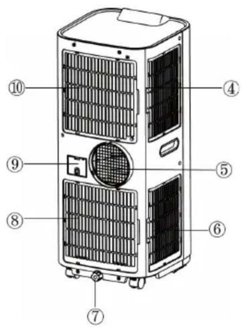
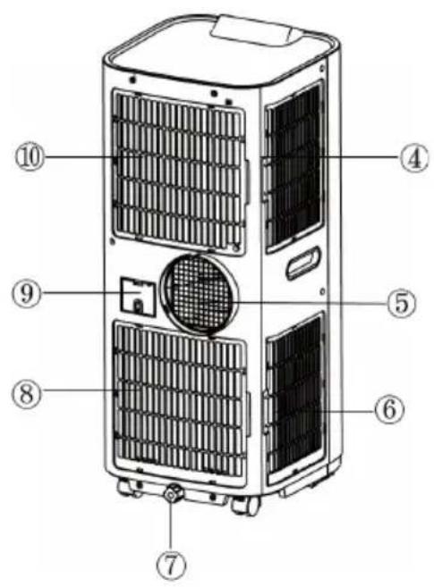
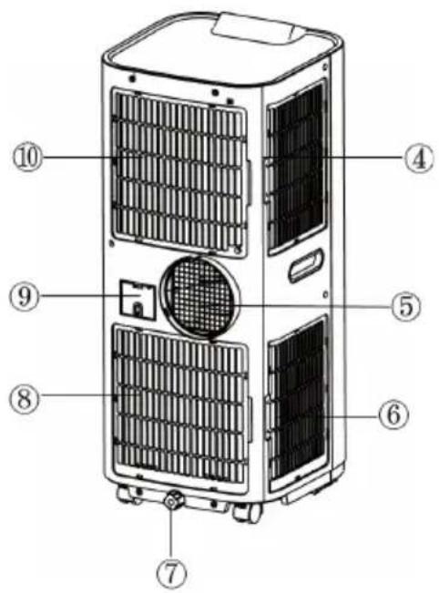
DEVICE DESCRIPTION
Front Back
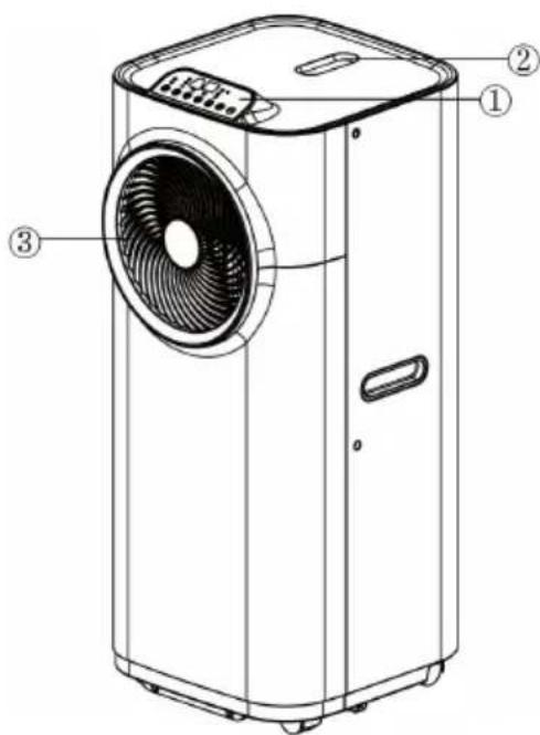
1 Control panel
2 Remote control
3 Airoutlet
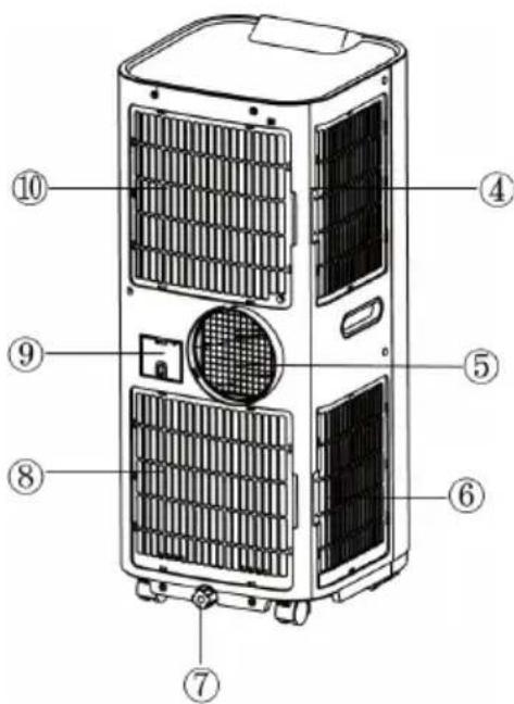
4 Air inlet
5 Exhaust air outlet
6 Airinlet
7 Water stopper/drainage point
8 Airinlet
9 Cord storage
10 Airinlet
Accessories
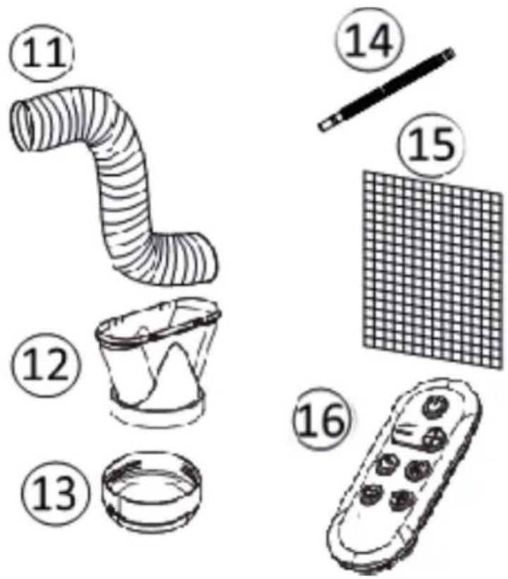
11 Exhaust hose
12 Adaptor - for insertion over hose and into window spacer (or into hole in the wall/ window).
13 Connector for exhaust pipe
14 Drain tube for continuous drainage
15 Active carbon filter
16 Remote control
INSTALLATION
Using the connector
natural_image
Line drawing of a washing machine in a corner with window frame and 50cm dimension label (no text or symbols on the device itself)
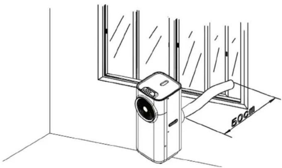
Have a 160 mm diameter hole in the wall or window.
Feed exhaust hose through the window or wall and attach the threaded adaptor from the outside as shown.
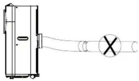
Mounting of the exhaust pipe
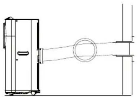
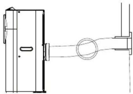
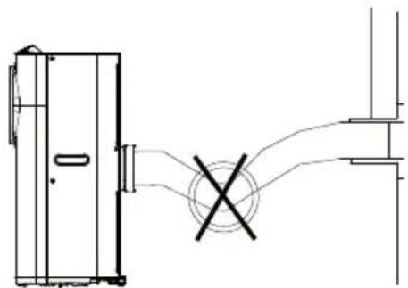
Use only the hose provided and clip exhaust hose to the back of the air conditioner. Avoid kinks and bends in the exhaust hose as this will cause expelled moist air to build up causing the unit to overheat and shut down. Figure 7 & 8 show correct position. The hose may be extended from 300 mm to 1500 mm but for maximum efficiency use the shortest length possible.
natural_image
Technical line drawing of a mechanical assembly with no visible text or symbols
RIGHT
natural_image
Technical line drawing of a mechanical assembly with no visible text or symbols
RIGHT
natural_image
Pure technical line drawing of a mechanical or electrical component without any text, numbers, or symbols
WRONG
natural_image
Pure technical line drawing of a mechanical component with no text or symbols
WRONG
ATTENTION: The length of the exhaust pipe is specially designed according to the specification of this product. Do not replace or prolong it with your own private hose as this could cause the unit to malfunction!
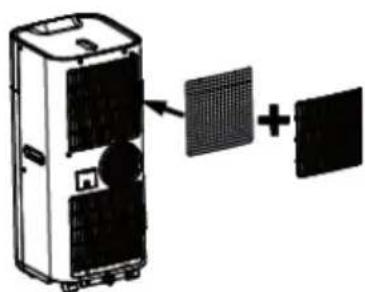
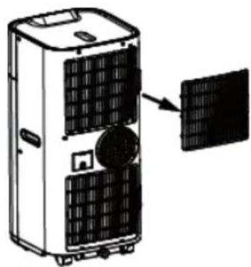
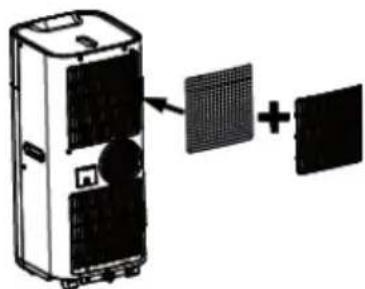
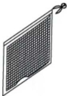
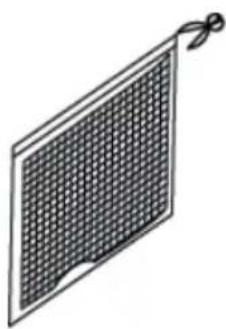
INSTALLATION OF THE CARBON FILTER
- Remove the plastic filter from the unit.
- Remove the active carbon filter from its plastic bag.
- Place the active carbon filter onto the unit.
- Replace the plastic filter on to the unit.
natural_image
Diagram of a large industrial air conditioner unit with cooling fan and solar panel, showing internal components and a close-up view of the unit (no text or symbols)

natural_image
Illustration of a solar panel with a grid pattern and a ribbon (no text or symbols)
natural_image
Diagram showing a device with two panels and a combined grid, no text or symbols present
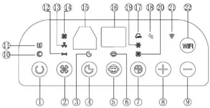
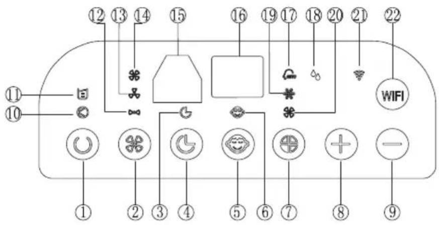
OPERATION
Control panel

1 ON/OFF (power) soft touch button
2 Speed (ventilation) soft touch button
3 "Timer" indicator
4 "Timer" soft touch button
5 "Sleeping" model soft touch button
6 "Sleeping" model indicator
7 Mode (function) option soft touch button
8 'Temperature up' soft touch button
9 'Temperature down' soft touch button
10 Indicator for compressor operation
11 "Full Water" indicator
12 Low ventilation indicator
13 Middle ventilation indicator
14 High ventilation indicator
15 Receiver for remote control
16 Display window
17 Automatic mode indicator
18 DEHUMIDIFY(DRY) mode indicator
19 Cooling mode indicator
20 Fan mode indicator
21 WiFi mode indicator
22 WIFI mode button
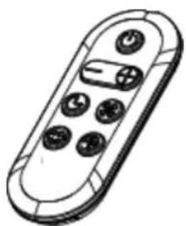
All the above functions can also be performed with the supplied remote control.
This remote control requires battery CR2032 x 1pc to operate
natural_image
Line drawing of a remote control device with buttons and a plus button (no text or symbols)
Turning ON/OFF
- Press ON/OFF soft touch button, the unit will start automatically. If the ambient temperature is higher or equal to 24 °C, the unit will work in cooling mode. If it is below 24 °C, the unit will work in ventilation mode (low fan).
- Indicators of the functions in progress come on at the same time.
The display window shows the ambient room temperature from 0 °C to 50 °C .
- To turn the unit off, press ON/OFF button again.
Setting mode/function
Press MODE button to select required working mode: automatic, cooling, fan or dehumidify (dry). The indicator of your selected mode lights on.
Setting temperature
- Press 'Temperature up' or 'Temperature down' button to regulate the temperature you desired.
- The display window will show the temperature you set as you press 'Temperature up' or 'Temperature down' button. Otherwise, it will always show the ambient temperature.
- The pre-setting temperature of this machine is: 24 °C for cooling.
Setting ventilation speed
- Press SPEED button to choose the ventilation speed you need, high, medium or low. The indicator of high, medium or low ventilation will light on at the same time.
- If the unit is in AUTO mode, it will choose the ventilation speed automatically according to the ambient temperature (the related indicators will light on), at this time, the SPEED and TEMPERATURE UP & DOWN buttons are invalid.
Setting timer
- Press TIMER button to set the operating hours you desired (1 to 24 hours, the timer indicator will light on). When the set time has been reached, the machine will turn off automatically. The display window will show the hour(s) you set as you press TIMER button. If the timer button is not pressed, the unit will work continuously.
- By pressing the timer but without turning on the other functions, you can PRE-SET the time for the machine to work. For example, if you press the timer to '2', the unit will work automatically after 2 hours.
Sleep function
- In cooling mode, by pressing the SLEEP button, the set temperature will increase 1 °C at the 1st hour, another 1 °C at the second hour, then keeps at that temperature.
- In sleep mode, the ventilation will keep at low speed. Re-press the SLEEP button, the setting temperature and ventilation speed will return to the pre-selected one.
- The unit will shut down automatically after the SLEEP function running for 12 hours.
-
Please note, the sleep function is not available while the machine is working in AUTO, FAN (ventilation) or DEHUMIDIFICATION mode.
-
When the machine is in Sleep function, the Fan Speed would turn to be LOW speed.
Dehumidify (DRY) mode
In dehumidify (DRY) mode, the temperature cannot be adjusted, the ventilation will fix at low speed. When the unit is operating in Dehumidify (DRY) mode, humidity extracted from the air is collected in an internal tank. If the tank reaches full, the compressor and motor cut out automatically. At the same time, the "Water Full" indicator comes on. An alarm will also sound. When the tank is full, drain the water as shown in the page concerning "DRAINAGE". You may also use the unit without having to empty the tank so often by using "continuous drainage", please also refer to the page about "DRAINAGE".
Self-diagnosis
This machine is equipped with self-diagnosis function. If something is wrong in the machine, the display window will show the sign: E1, E2, E3 or E5, which reflects different condition. At this time, please call your service centre.
Notes
- To prolong the compressor's life, after switch-off of the unit, please wait for 3 minutes (at least) before re-switch.
- The cooling system will switch off if the ambient temperature is lower than the set one. The ventilation, however, keeps working on the set level. If the ambient temperature rises above the selected level, the cooling will return to work.
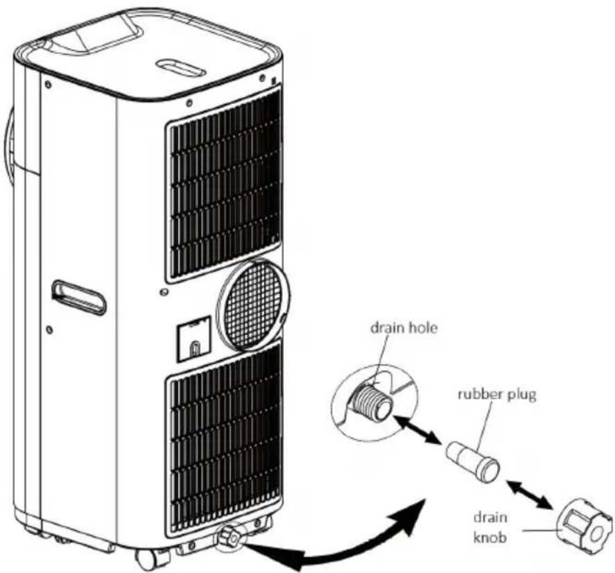
DRAINAGE
During the process of cooling, some water will be extracted from the air into the unit. If the reservoir is full, both of the compressor and motor will stop and the units would buzz (you can press any button to stop the buzz). The W.F. indicator will flash to show you.
To make the cooling work again, please empty the water by one of the following ways:
- Turn off the air conditioner and avoid moving it when full.
- Position a container (a water tray for example) underneath the drain hole.
- Remove the drain knob & rubber plug from the drain hole and allow the water to drain out.
-
When the container is almost full, replace the rubber plug in the drain hole and empty the water tray.
-
Repeat until the unit is emptied.
-
Replace the rubber plug and tighten the drain knob firmly.
-
Switch on the unit - the full water or compressor operating indicator should not be flashing.
If you wish to operate the unit without the need to empty the water tank, please:
- Remove the drain knob and rubber plug and retain for future use.
- Connect the drain tube supplied to the water outlet as shown and locate the other end into a drain.
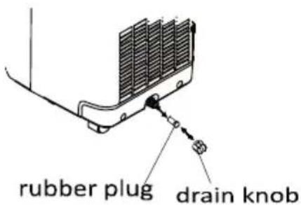
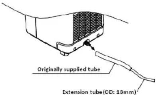
The drain tube may be extended by adding an extension tube and using a suitable connector.
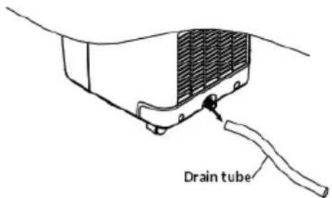
Please note :
- The drain must be at or below the outlet level.
- Flashing 'full water' indicator will not function in this mode of drainage.
- If you want to extend the water tube, you can connect it with another tube (OD: 18 mm).
HOW TO INSTALL THE WINDOW SEAL
Installing the window sealing is easy. You can attach it to a tilted window or to a laterally opened window. Our demonstration is performed on a laterally opened window. It is especially suitable for low positions of the exhaust pipe.
The velcro tape must be attached on three sides. Leave out the side with the window being connected to the frame. Clean the frame and dry it first, so that the tape sticks.
| 123 | | |
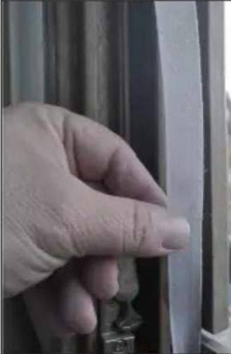 | 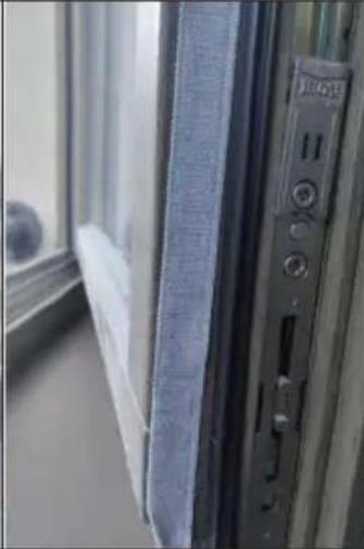 | 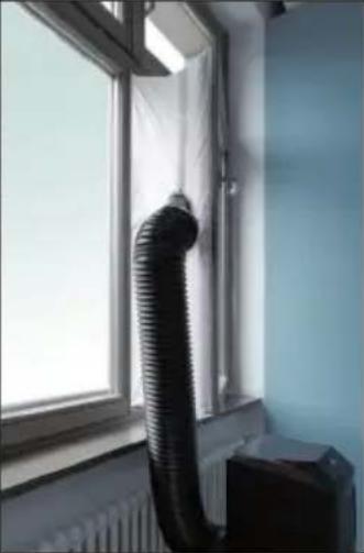 |
| Attach the velcro tape on the left, on the top and on the bottom of the window frame.We recommend that you cut the tape into strips for each window side first. | Now attach the velcro tape to the inner window sides. | Stick the window sealing to the velcro strips on the window frame first (starting with the top), then on the velcro strips on the window.Push the exhaust air tube of the air conditioner through the hole, which can be adjusted in height and size. |
CLEANING AND CARE
Always unplug the air conditioner from the mains before cleaning.
To maximize the efficiency of the air conditioner, clean regularly.
Cleaning the housing
Use a soft, damp cloth to wipe the body clean.
Never use aggressive chemicals, gasoline, detergents, chemically treated cloths, or other cleansing solutions. These all could possibly hurt the cabinet.
Cleaning the filter
Use a vacuum cleaner or tap the filter lightly to remove loose dust and dirt from the filters and then rinse thoroughly under running water (no hotter than 40 °C).
Dry thoroughly before replacing.
Notice! Never operate the unit without the filters.
End of season storage
- Drain any water in the unit before completely operating the unit on ventilation only mode for a few hours, to thoroughly dry the inside.
- Clean or change the filter.
• Unplug and store the power cord.
- Replace in the original carton or cover for storage.
TROUBLESHOOTING
| Problem Check these issues |
| The air conditioner does not run. | Is the air conditioner plugged in? |
| Is there a power failure? |
| Is the comp / 'full water' indicator flashing? |
| Is the room temperature below the set temperature? |
| The machine seems to do little. | Is there direct sunshine? (Please put down the curtain.) |
| Are too many windows or doors open? |
| Are there too many people in the room? |
| Is there something in the room producing lots of heat? |
| The machine seems to do nothing. | Is the filter dusty, contaminated? |
| Is the air intake or output blocked up? |
| Is the room temperature below your selected temperature? |
| Too noisy. | Is the machine positioned unevenly so as to create vibration? |
| Is the floor underneath the machine uneven? |
| The compressor does not operate. | It is possible the overheat protection of the compressor is on. Just wait for the temperature to drop? |
Error codes for the electrician
| Code Meaning |
| E1 Resin sensor on the evaporator broken down. |
| E2 Copper sensor on the discharge tube broken down. |
| E3 TC sensor is loose or broken down. Please check and replace it. |
| E5 Device overheated. The compressor and fan motor stop.Press the ON/OFF button to check, if E5 signal still exists. If that is the case, that meand dthe compressor system is abnormal. |
Warning
- The air conditioning system must be kept and transported upright. Otherwise, irreparable compressor damage may occur. Leave the unit for at least 24 hours before putting it into operation.
- Switch off the device and disconnect it from the power supply before cleaning.
- Make sure that the product creates a steady stream of air. Ensure the air inlets and outlets are not blocked.
• To prevent leaks, operate this unit on a horizontal surface.
- Any person performing work on a refrigerant circuit should have a current certificate from an industry-accredited assessment body. This ensures competence for the safe handling of refrigerants according to an industry-recognised assessment specification.
- If the device stops working, dispose of it properly.
- Store the device in a well-ventilated place when not in use.
- Store the device so that it is not damaged.
- Repairs may only be carried out by the manufacturer or an authorised specialist company.
- The cables connected to the device may contain potential ignition sources.
- Do not damage any components of the refrigerant circuit. Escaping refrigerant may not be noticed because it is odourless.
- Maintenance and repairs must be carried out under the supervision of specialists in the use of fl ammable refrigerants.
- Limit the piping to a minimum.
- Be careful not to damage the piping.
- Appliances with fl ammable refrigerants may only be installed in a well-ventilated room.
- Comply with national gas regulations.
- All mechanical connections must be freely accessible for maintenance purposes.
CAUTION
Risk of fi re!
This device contains the fl ammable refrigerant R290. If the refrigerant escapes and is exposed to an external ignition source, there is a risk of fire.
DEVICE CONTROL BY SMARTPHONE
If you integrate the device into your home WiFi, you can conveniently operate it via the associated Klarstein app. The app not only allows you to remotely control the device via your smartphone, but also gives you access to recipes and additional information.
Follow these steps to connect your smartphone to your Klarstein device:
- Download the Klarstein app first by scanning the QR code with your smartphone (see below), or download it directly from App Store or Google Play.
- Make sure your smartphone is connected to the same WiFi network that your Klarstein device is to be connected to.
- Open the Klarstein app.
- Sign in to your account. If you do not have an account, sign up in the Klarstein app.
- Follow the instructions from the app.
App Download
Use the scan function of your smartphone to scan the QR code and save the app on your smartphone.
Note: The app provides further information on how to use the app and help on how to connect to your device as soon as you open it for the first time.
| iOS Android | |
 |  |
Troubleshooting connection problems
If your Klarstein device cannot be found in the WLAN, check the following:
• Is the device plugged in?
• Is the WiFi feature of my phone enabled?
- Is the WiFi function of the Klarstein device activated? (Follow the instructions in the app)
- Has the WLAN password been entered correctly?
- Are the router, Klarstein device and smartphone in the immediate vicinity during the connection attempt? (Ideally no more than 5 m apart)
- If you have deactivated the 2.4 GHz band in the settings of your wireless router, activate it in your router settings.
Note: For further help, follow the instructions in the app when setting up the connection.
TECHNICAL DATA
| Item number 10034664, 10034665,10035739, 10035740 | 10034666, 10034667,10035737, 10035738 |
| Power supply 220-240 V ~50 Hz |
| Power consumption 1308 W / 6.0 A 1120 W / 5.1 A |
| Cooling capacity 12000 Btu/h ~3.4 kW 10000 Btu/h ~2.9 kW |
| Air volume (max.) 366 m ^2 /h 385 m | ^2 /h |
| Moisture removal 48 L/day 31.5 L/day | |
| Refrigerant R290 | |
| WiFi standard | 802.11 b/g/n |
| WiFi frequency | 2,4 GHz |
| WiFi radio-frequency power(max.) | 20 dBm |
Information according to regulation (EU) No. 626/2011
Supplier's trademark: Klarstein
Supplier's model identifier: 10034664,
10034665,
10035739,
10035740
Inside sound power levels at standard rating conditions on cooling mode in dB: 65 dB
Refrigerant (R290) leakage contributes to climate change. Refrigerant with lower global warming potential (GWP) would contribute less to global warming than a refrigerant with higher GWP, if leaked to the atmosphere. This appliance contains a refrigerant fluid with a GWP equal to 3. This means that if 1 kg of this refrigerant fluid would be leaked to the atmosphere, the impact on global warming would be 3 times higher than 1 kg of CO_2 , over a period of 100 years. Never try to interfere with the refrigerant circuit yourself or disassemble the product yourself and always ask a professional.
Energy efficiency ratio ( EER_rated ): 2,6
Energy efficiency class: A
Energy consumption 1,3 kWh per 60 minutes, based on standard test results. Actual energy consumption will depend on how the appliance is used and where it is located.
Cooling capacity P_rated in kW: 3,4 kW
Information according to regulation (EU) No. 206/2012
| Model identifier(s) 10034664, 10034665, | 10035739,10035740 |
| Description Symbol Value Unit | | | |
| Rated capacity for cooling P | rated for cooling | 3,4 kW | |
| Rated capacity for heating P | rated for heating | kW | |
| Rated power input for cooling P | EER | 1,3 kW | |
| Rated power input for heating P | COP | -kW | |
| Rated Energy efficiency ratio EERd 2,6 - | | | |
| Rated Coefficient of performance | COPd | -- | |
| Power consumption in thermostat-off mode | P_TO | - | W |
| Power consumption in standby mode | P_SB | 0,38 | W |
| Electricity consumption of single/double duct appliances(indicate for cooling and heating separately) | DD: Q_DD SD: Q_SD | 1,3 DD: kWh/aSD: kWh/h |
| Sound power level | L_WA | 65 | dB(A) |
| Global warming potential | GWP | 3 | kgCO2eq. |
| Contact detailsfor obtaining more information | Chal-Tec GmbH,Wallstraße 16, 10179 Berlin, Germany. |
Information according to regulation (EU) No. 626/2011
Supplier's trademark: Klarstein
Supplier's model identifier: 10034666,
10034667,
10035737,
10035738
Inside sound power levels at standard rating conditions on cooling mode in dB: 65 dB
Refrigerant (R290) leakage contributes to climate change. Refrigerant with lower global warming potential (GWP) would contribute less to global warming than a refrigerant with higher GWP, if leaked to the atmosphere. This appliance contains a refrigerant fluid with a GWP equal to 3. This means that if 1 kg of this refrigerant fluid would be leaked to the atmosphere, the impact on global warming would be 3 times higher than 1 kg of CO_2 , over a period of 100 years. Never try to interfere with the refrigerant circuit yourself or disassemble the product yourself and always ask a professional.
Energy efficiency ratio ( EER_rated ): 2,6
Energy efficiency class: A
Energy consumption 1,1 kWh per 60 minutes, based on standard test results. Actual energy consumption will depend on how the appliance is used and where it is located.
Cooling capacity P_rated in kW: 2,9 kW
Information according to regulation (EU) No. 206/2012
| Model identifier(s) 10034666, 10034667, | 10035737,10035738 |
| Description Symbol Value Unit | | | |
| Rated capacity for cooling P | rated for cooling | 2,9 kW | |
| Rated capacity for heating P | rated for heating | kW | |
| Rated power input for cooling P | EER | 1,1 kW | |
| Rated power input for heating P | COP | -kW | |
| Rated Energy efficiency ratio EERd | 2,6 - | | |
| Rated Coefficient of performance | COPd | -- | |
| Power consumption in thermostat-off mode | P_TO | - | W |
| Power consumption in standby mode | P_SB | 0,38 | W |
| Electricity consumption of single/double duct appliances(indicate for cooling and heating separately) | DD: Q_DD SD: Q_SD | 1,1 DD: k | Wh/aSD: kWh/h |
| Sound power level | L_WA | 65 | dB(A) |
| Global warming potential | GWP | 3 | kgCO2eq. |
| Contact detailsfor obtaining more information | Chal-Tec GmbH,Wallstraße 16, 10179 Berlin, Germany. |
DISPOSAL CONSIDERATIONS
natural_image
Symbol of a trash bin crossed with a diagonal line, representing no waste or discharge (no text or labels)
If there is a legal regulation for the disposal of electrical and electronic devices in your country, this symbol on the product or on the packaging indicates that this product must not be disposed of with household waste. Instead, it must be taken to a collection point for the recycling of electrical and electronic equipment. By disposing of it in accordance with the rules, you are protecting the environment and the health of your fellow human beings from negative consequences. For information about the recycling and disposal of this product, please contact your local authority or your household waste disposal service.
This product contains batteries. If there is a legal regulation for the disposal of batteries in your country, the batteries must not be disposed of with household waste. Find out about local regulations for disposing of batteries. By disposing of them in accordance with the rules, you are protecting the environment and the health of your fellow human beings from negative consequences.

Manufacturer:
Chal-Tec GmbH, Wallstrasse 16, 10179 Berlin, Germany.
Importer for Great Britain:
Chal-Tec UK limited
Unit 6 Riverside Business Centre
Brighton Road
Shoreham-by-Sea
BN43 6RE
United Kingdom
The complete declaration of conformity of the manufacturer can be found at the following link: use.berlin/10034664
Chère cliente, cher client,
SOMMAIRE
natural_image
Line drawing of a washing machine mounted on a wall, with a 50mm dimension label (no text or symbols beyond the measurement)
natural_image
Diagram of a large industrial air conditioner unit with cooling fan and solar panel, showing internal components and a close-up view of the unit (no text or symbols)
natural_image
Illustration of a solar panel with a grid pattern and a ribbon (no text or symbols)

natural_image
Diagram showing a device with two panels and a combined grid, no text or symbols present
Panneau de commande
natural_image
Line drawing of a remote control device with buttons and a plus button (no text or symbols)
natural_image
Diagram of a vehicle cooling system with heat exchangers and a sensor (no text or labels)
Bouchon en caoutchouc
Verrou de vidange
natural_image
Symbol of a trash bin crossed with a diagonal line, no text or numbers present

Fabricant :
Chal-Tec GmbH, Wallstraße 16, 10179 Berlin, Allemagne.
Unit 6 Riverside Business Centre
Brighton Road
Shoreham-by-Sea
BN43 6RE
United Kingdom
CONTENIDO
natural_image
Line drawing of a washing machine in a corner with a 50cm dimension label (no text or symbols on the device itself)
natural_image
Diagram of a large industrial air conditioner unit with cooling fan and solar panel, showing internal components (no text or labels)
aparato.
natural_image
Illustration of a solar panel with grid pattern and attached cable (no text or symbols)
natural_image
Diagram showing a device with two panels mounted on top, connected to a grid and finally into a single panel (no text or symbols present)
FUNCIONAMIENTO
Panel de control
natural_image
Line drawing of a remote control device with six buttons and a plus button (no text or symbols)
natural_image
Technical line drawing of a heat exchanger or cooling unit with cooling fins and a hanging sensor (no text or symbols)
natural_image
Symbol of a trash bin crossed with a diagonal line, no text or numbers present
Chal-Tec UK limited.
Unit 6 Riverside Business Centre
Brighton Road
Shoreham-by-Sea
BN43 6RE
Reino Unido
INDICE
Lato posteriore
natural_image
Line drawing of a washing machine in a corner with a 50cm dimension label (no text or symbols on the device itself)
natural_image
Diagram of a large industrial air conditioner unit with cooling fan and solar panel, showing internal components (no text or labels)

natural_image
Illustration of a solar panel with a grid pattern and a ribbon (no text or symbols)

natural_image
Diagram showing a device with two panels and a grid, connected to a plus button (no text or symbols present)
natural_image
Line drawing of a remote control device with six buttons and a plus button (no text or symbols)
natural_image
Technical line drawing of a mechanical component with no visible text or symbols
natural_image
Symbol of a trash bin crossed with a diagonal line, no text or numbers present
Unit 6 Riverside Business Centre
Brighton Road
Shoreham-by-Sea
BN43 6RE
Regno Unito