
MH60J76M21B - Basket MIDEA - Free user manual and instructions
Find the device manual for free MH60J76M21B MIDEA in PDF.

| Brand | Midea |
| Model | MH60J76M21B |
| Product type | Kitchen range hood |
| Rated voltage | 220-240 V ~ 50 Hz |
| Rated power | 46.5 W |
| Lighting power | 1.5 W (LED) |
| Motor input power | 45 W |
| Maximum air flow | 400 m³/h |
| Maximum noise level | ≤ 60 dB(A) |
| Exhaust duct diameter | 150 mm (reducible to 120 mm) |
| Number of speeds | 3 (low, medium, high) |
| Control type | Push-button switches |
| Lighting | LED, power 1.5 W |
| Grease filters | Metal, dishwasher safe |
| Activated carbon filters | Optional, replace every 4 months |
| Operating mode | Extraction or recirculation |
| Minimum distance to cooking surface | 650 mm |
| Energy efficiency class | A+ |
| Annual energy consumption | 12.3 kWh/year |
Frequently Asked Questions - MH60J76M21B MIDEA
User questions about MH60J76M21B MIDEA
0 question about this device. Answer the ones you know or ask your own.
Ask a new question about this device
Download the instructions for your Basket in PDF format for free! Find your manual MH60J76M21B - MIDEA and take your electronic device back in hand. On this page are published all the documents necessary for the use of your device. MH60J76M21B by MIDEA.
USER MANUAL MH60J76M21B MIDEA
natural_image
Simple line drawing of a rectangular block with two inner rounded rectangles stacked vertically (no text or symbols)Dunstabzugshaube
BENUTZERHANDBUCH
MH90J76M21BB
MH60J76M21B
PRODUKTINSTALLATION....07
PRODUKTDATENBLATT FÜR
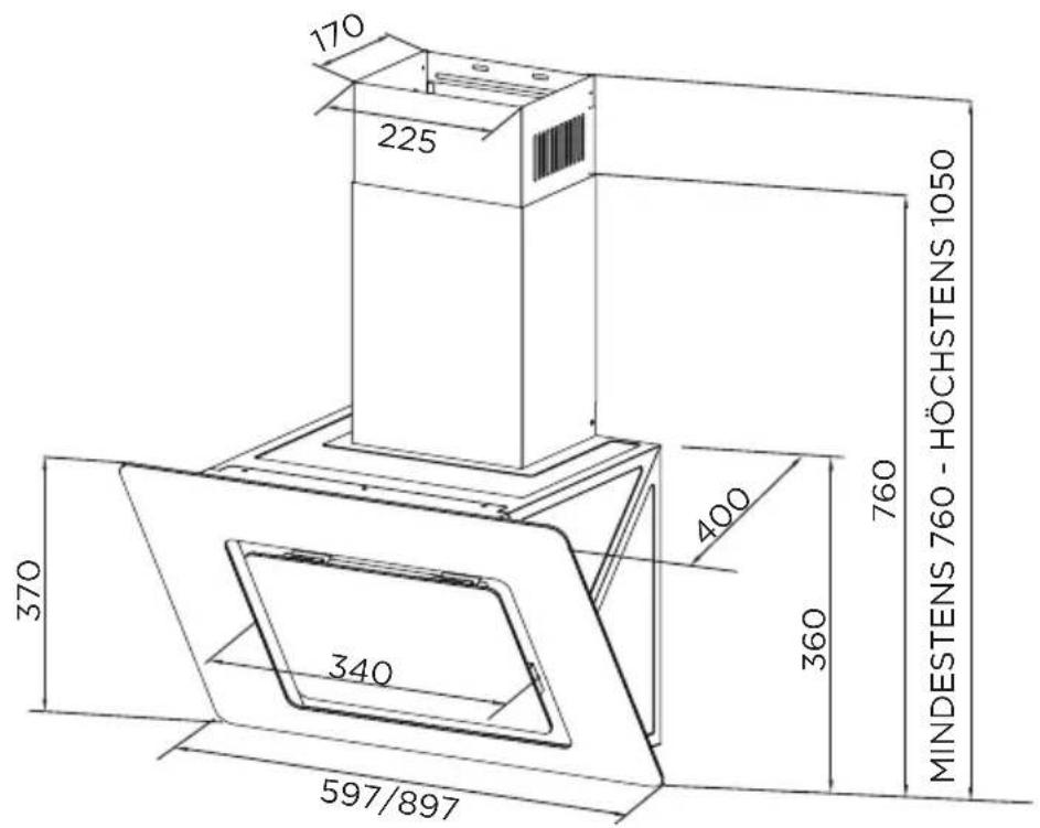
Einheit: mm
PRODUKTINSTALLATION
natural_image
Simple line drawing of a rectangular box with a top handle and bottom frame (no text or symbols)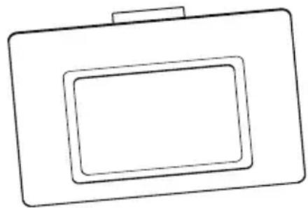
natural_image
Simple line drawing of a rectangular device with two nested square cutouts (no text or symbols)Richtig Falsch
natural_image
Technical diagram of a mechanical ventilation system with airflow arrows (no text or labels)Verbindungen
natural_image
Diagram showing a device being processed from an internal component, with no visible text or symbols.Oberer dekorativer Schornstein
natural_image
Technical diagram showing a mechanical assembly with a dashed circular inset view of a cabinet and a magnified inset of a coiled spring (no text or symbols present)BETRIEBSANLEITUNG
natural_image
Illustration of a hand interacting with a tablet device, showing a finger pointing at the screen (no text or symbols present)natural_image
Technical line drawings of two mechanical components with internal cutouts (no text or symbols)natural_image
Line drawing of two hands interacting with a surface (no text or symbols)FEHLERBEHEBUNG
natural_image
Symbol of a trash bin crossed with two crossed lines, no text or labels presentnatural_image
Recycling symbol with four arrows forming a triangle (no text or labels)DATENSCHUTZHINWEIS
make yourself at home
natural_image
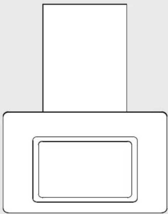
Simple geometric diagram with two nested rectangles, no text or symbols presentCooker Hood
USER MANUAL
MH90J76M21BB
MH60J76M21B
THANK YOU LETTER
Thank you for choosing Midea! Before using your new Midea product, please read this manual thoroughly to ensure that you know how to operate the features and functions that your new appliance offers in a safe way.
CONTENTS
THANK YOU LETTER 01
SAFETY INSTRUCTIONS 02
SPECIFICATIONS 04
PRODUCT OVERVIEW 05
PRODUCT INSTALLATION 07
OPERATION INSTRUCTIONS 11
CLEANING AND MAINTENANCE 11
TROUBLE SHOOTING 13
TRADEMARKS, COPYRIGHTS AND LEGAL STATEMENT 13
DISPOSAL AND RECYCLING 14
DATA PROTECTION NOTICE 15
PRODUCT FICHE FOR DOMESTIC RANGE HOOD 16
SAFETY INSTRUCTIONS
Intended Use
The following safety guidelines are intended to prevent unforeseen risks or damage from unsafe or incorrect operation of the appliance. Please check the packaging and appliance on arrival to make sure everything is intact to ensure safe operation. If you find any damage, please contact the retailer or dealer. Please note modifications or alterations to the appliance are not allowed for your safety concern. Unintended use may cause hazards and loss of warranty claims.
Explanation of Symbols

Danger
This symbol indicates that there are dangers to the life and health of persons due to extremely flammable gas.

Warning of electrical voltage
This symbol indicates that there is a danger to life and health of persons due to voltage.

Warning
The signal word indicates a hazard with a medium level of risk which, if not avoided, may result in death or serious injury.

Caution
The signal word indicates a hazard with a low degree of risk which, if not avoided, may result in minor or moderate injury.

Attention
The signal word indicates important information (e.g. damage to property), but not danger.

Observe instructions
This symbol indicates that a service technician should only operate and maintain this appliance in accordance with the operating instructions.
Read these operating instructions carefully and attentively before using/commissioning the unit and keep them in the immediate vicinity of the installation site or unit for later use!
- The instructions for Use apply to several versions of this appliance. Accordingly, you may find descriptions of individual features that do not apply to your specific appliance.
- This appliance is not intended for use by persons (including children) with reduced physical, sensory or mental capabilities, or lack of experience and knowledge, unless they have been given supervision or instruction concerning use of the appliance by a person responsible for their safety.
• Children should be supervised to ensure that they do not play with the appliance. - This appliance can be used by children aged from 8 years and above and persons with reduced physical, sensory or mental capabilities or lack of experience and knowledge if they have been given supervision or instruction concerning use of the appliance in a safe way and understand the hazards involved. (EN 60335-1 & EN 60335-2-31)
• Children shall not play with the appliance. (EN 60335-1 & EN 60335-2-31) - Cleaning and user maintenance shall not be made by children without supervision. (EN 60335-1 & EN 60335-2-31)
- If the supply cord is damaged, it must be replaced by the manufacturer or its service agent or a similarly qualified person in order to avoid a hazard.
- This appliance incorporates an earth connection for functional purposes only.
- There shall be adequate ventilation of the room when the range hood is used at the same time as appliances burning gas or other fuels (not applicable to appliances that only discharge the air back into the room).
- There is a fire risk if cleaning is not carried out in accordance with the instructions;
- Do not flame under the range hood.
- CAUTION: Accessible parts may become hot when used with cooking appliances.
- The air must not be discharged into a flue that is used for exhausting fumes from appliances burning gas or other fuels (not applicable to appliances that only discharge the air back into the room).
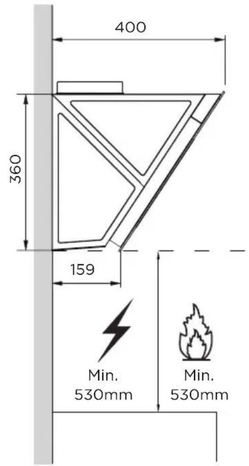
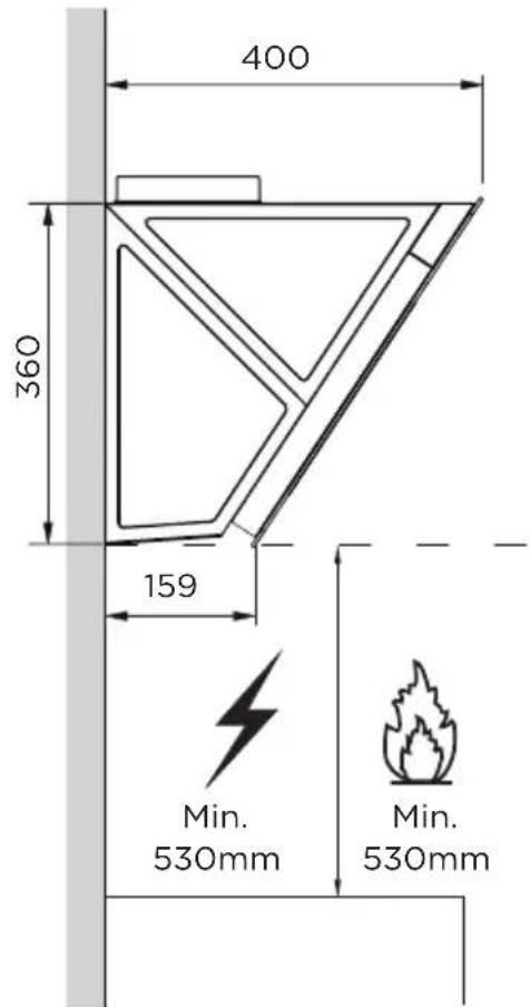
- The minimum distance between the supporting surface for the cooking vessels on the hob and the lowest part of the range hood is 650 mm.
- Regulations concerning the discharge of air have to be fulfilled.
- The appliance uses 4 hob elements at most.
The manufacturer will not be held liable for any damages resulting from incorrect or improper installation. - Check that the mains voltage corresponds to that indicated on the rating plate fixed to the hood.
- For Class I appliances, check that the domestic power supply guarantees adequate earthing.
-
Connect the extractor to the exhaust flue through a pipe of minimum diameter 120mm.
-
The route of the flue must be as short as possible.
- Do not connect the extractor hood to exhaust ducts carrying combustion flumes (boilers, fireplaces, etc.).
- If the instructions for installation for the gas hob specify a greater distance specified above, this has to be taken into account.
- The extractor hood has been designed exclusively for domestic use to eliminate kitchen smells.
- Never use the hood for purposes other than for which it has been designed.
- Never leave high naked flames under the hood when it is in operation.
- Adjust the flame intensity to direct it onto the bottom of the pan only, making sure that it does not engulf the sides.
- Deep fat fryers must be continuously monitored during use: overheated oil can burst into flames.
- The cooker hood and its filter should be cleaned regularly according to the instruction.
- Switch off or unplug the appliance from the mains supply before carrying out any maintenance work.
- Clean the hood using a damp cloth and a neutral liquid detergent.
SPECIFICATIONS
| MH60J76M21B/MH90J76M21BBProduct Model | |
| Voltage | 220V-240V-/50Hz |
| Rated Power | 46.5 W |
| Lighting Power | 1.5 W |
| Motor Input Power | 45 W |
| Diameter of air tube | 150 mm |
| Air flow | 400 m^3/h |
| Noise | ≤slant 60 dB(A) |
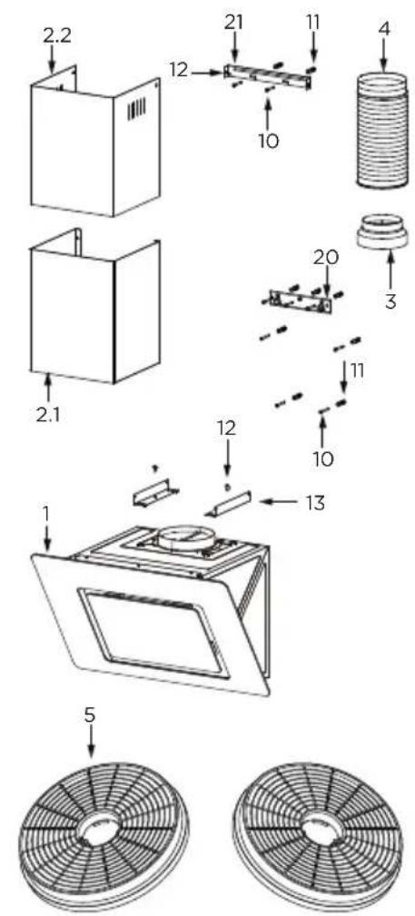
PRODUCT OVERVIEW
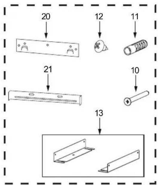
Components
| Ref. | Qty. | Product Components |
| 1 | 1 | Hood Body, complete with: Controls, Light, Blower,Filter. |
| 2.1 | 1 | Lower Decorative Chimney (optional) |
| 2.2 | 1 | Upper Decorative Chimney (optional) |
| 3 | 1 | Flange (optional) |
| 4 | 1 | Exhaust Pipe |
| 5 | 2 | The Activated Charcoal filter (optional) |
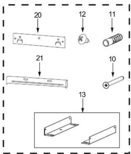
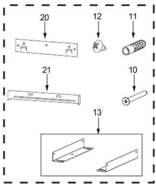
| Ref. | Qty. | Optional Installation Components |
| 10 | 7 | Screws 5 x 50 |
| 11 | 7 | Wall Plugs |
| 12 | 6 | Screws 4,2 x 9,5 |
| 13 2 Mounting Bracket | ||
| 20 | 1 | Hood fixing bracket (optional) |
| 21 1 Chimney fixing bracket(0/1 optional) | ||
Qty. Documentation
1 Instruction Manual
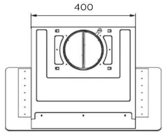
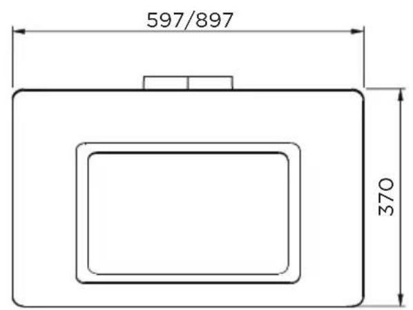
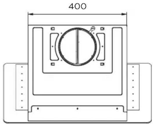
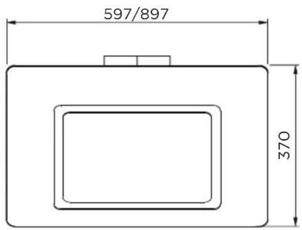
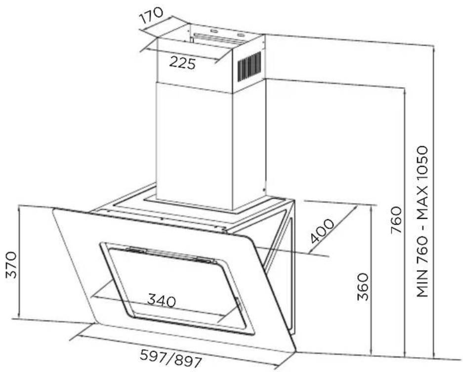
unit: mm
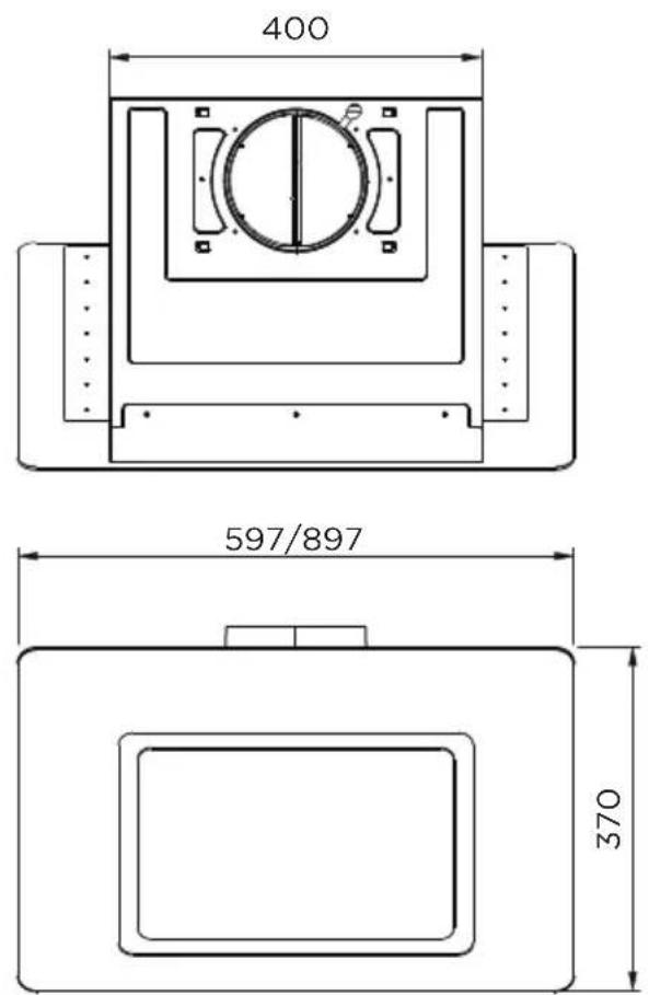
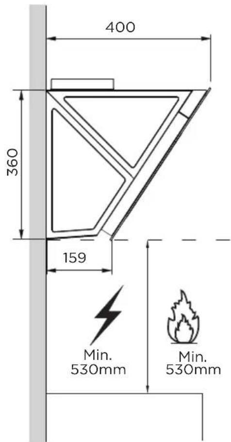
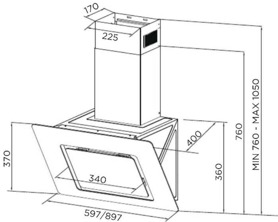
PRODUCT INSTALLATION
Wall Drilling And Bracket Fixing
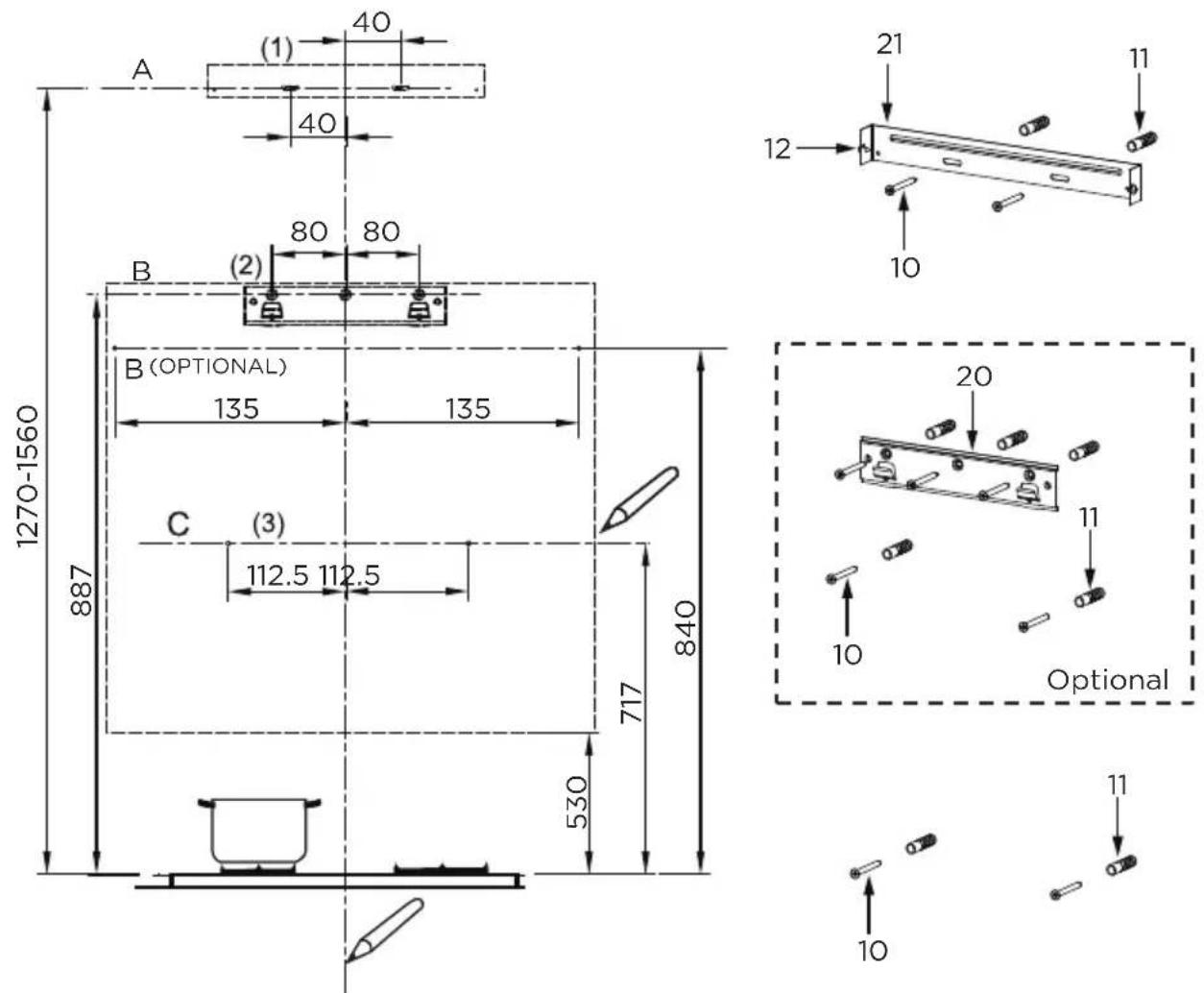
As a first step, proceed with the following drawings:
- A vertical line up to the ceiling or up to the upper limit, at the center of the area in which the hood is to be fitted.
- A horizontal line A at 1270 - 1560 mm above the cooker top.
• A horizontal line B at a minimum 887 (840 optional) mm above the cooker top.
• A horizontal line C at a minimum 717 mm above the cooker top.
Mark Points:
- Mark a point (1) on the horizontal line A, 40 mm to the right of the vertical reference line.
- Repeat this operation on the other side, checking that the two marks are leveled.
- Mark a point (2) on the horizontal line B, 80 (135 optional) mm to the right of the vertical reference line.
- Repeat this operation on the other side and on the vertical reference line, checking that the three marks are leveled.
- Mark a point (3) on the horizontal line C, 112.5 mm to the right of the vertical reference line.
- Repeat this operation on the other side, checking that the two marks are on the same horizontal line.
Fix the brackets (Optional):
- Drill at the marked points (1) (2) (3), using a 10 mm drill bit.
- Insert the Wall Plugs 11 into the holes (1) (2) (3).
- Fix the hood fixing bracket 20 with 3 screws 10 (5 x 50) supplied with the hood.
- Fix a Chimney fixing bracket 21 with 2 screws 10 (5 x 50) supplied with the hood.
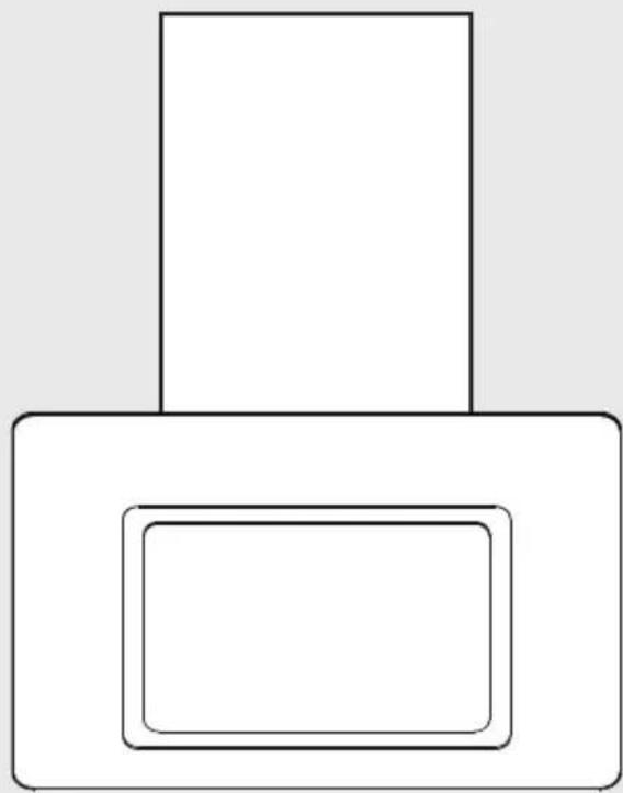
Hook The Hood Body
- Open the panel.
- Remove the Metal grease filter using the handles provided.
- Hook the hood body to the bracket 20.
• Level the hood body itself.
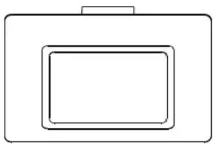
natural_image
Simple line drawing of a rectangular device with a top handle and bottom rectangle (no text or symbols)Right
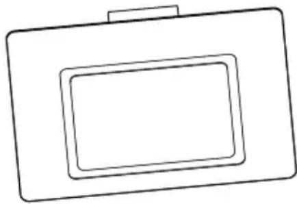
natural_image
Simple line drawing of a rectangular frame with a smaller square recess (no text or symbols)Wrong
- From the inside of the hood body, fix the screws 10 to Wall Plugs 11 at the points (3).
• Fit the filter into the hood. - Close the panel.
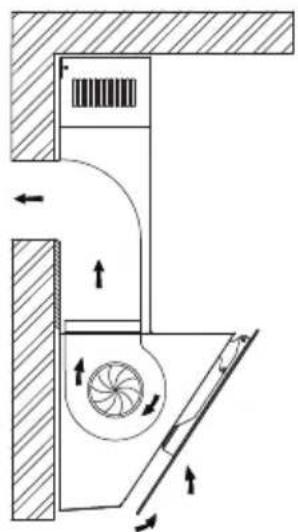
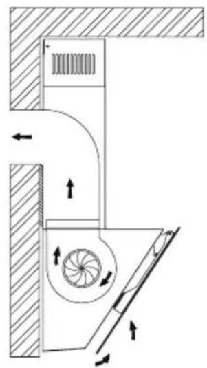
Choose a venting mode
Here two venting modes, extraction-air mode and recirculation mode, before installing, select one mode.
Extraction-air mode, the air is discharged out of the house by a pipe.
Recirculation mode, the air is purified and discharged into the house through two rows of holes on the adjustable decorative cover.
Note: For recirculation mode, no need pipe, install carbon filters.
when carbon filter attached, the suction power will be lowered.
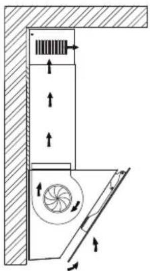
natural_image
Technical diagram of a mechanical ventilation system with airflow arrows and component layout (no text or labels)Recirculation mode Extraction-air mode
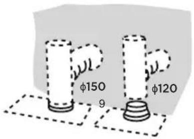
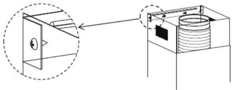
Connections
Ducted Version Air Exhaust System
When installing the ducted version, connect the hood to the chimney using either a flexible or rigid pipe 150 or 120 mm, the choice of which is left to the installer.
- To install a 120 mm air exhaust connection, insert the reducer flange 3 on the hood body outlet.
- Fix the pipe 4 in position using sufficient pipe clamps (not supplied).
- Remove possible charcoal filters.
The chimney can only be installed with exhausting hood.
Lower Decorative Chimney
- Fix a Chimney fixing bracket 21 onto the Lower Decorative Chimney with 2 screws 12(4.2 × 9.5) supplied with the hood.
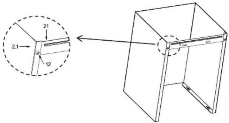
- Hook the brackets 13 onto the hood body, and fix them with 2 screws 12 (4.2 x 9.5), making sure that they are well seated.
- Slightly widen the two sides of the lower chimney and hook then between the brackets 13, fix the lower chimney onto the brackets 13 with 2 screws 12 (4.2 x 9.5) supplied with the hood.
natural_image
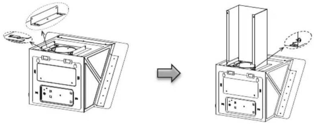
Diagram showing a device assembly before and after transformation, with no visible text or symbols.Upper Decorative Chimney
- Slightly widen the two sides of the upper chimney and hook them between the wall and the bracket 21 which is fixed on the Lower Decorative Chimney.
- Fix the upper chimney onto the bracket 21 with 2 screws 12 (4.2 x 9.5) supplied with the hood.
natural_image
Technical diagram showing a mechanical assembly with a dashed circular inset view of a component (no text or symbols present)OPERATION INSTRUCTIONS
Speed Adjustment. (For Some Models)
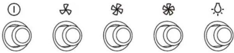
 | OFF MOTOR SWITCH: Press on this switch to stop the motor operation. |
 | SPEED SWITCH: Press on this switch, the motor runs at LOW speed. |
 | SPEED SWITCH: Press on this switch, the motor runs at MEDIUM speed. |
 | SPEED SWITCH: Press on this switch, the motor runs at HIGH speed. |
 | ON/OFF LIGHTING SWITCH: Press on this switch to turn on the lights, and press again to turn them off. |
CLEANING AND MAINTENANCE
Grease Filters
CLEANING METAL SELF-SUPPORTING GREASE FILTERS
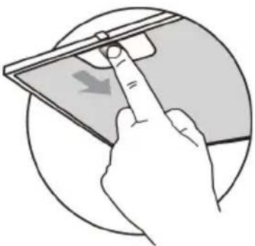
- The filters must be cleaned every 2 months of operation, or more frequently for particularly heavy usage, and can be washed in a dishwasher.
- Pull the comfort panels to open them.
- Remove the filters one by one pushing them towards the back side of the hood unit and simultaneously pulling downwards.
- Any kind of bending of the filters has to be avoided when washing them. Before fitting them again into the hood make sure that they are completely dry. (The color of the filter surface may change throughout the time but this has no influence to the filter efficiency).
- When fitting the filters into the hood pay attention that they are mounted in correct position the handle facing outwards.
- Close the comfort panel.
natural_image
Illustration of a hand interacting with a tablet device (no text or symbols visible)Activated Charcoal Filter (Recirculation Version)
• These filters are not washable and cannot be regenerated, and must be replaced approximately every 4 months of operation, or more frequently with heavy usage.
Replacing The Activated Charcoal Filter
- Open the comfort panels pulling them downwards.
- Remove the metal grease filters.
- Remove the saturated activated charcoal filter.
- Fit the new filters.
- Replace the metal grease filters.
- Close the comfort panel.
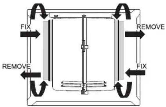
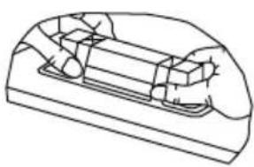
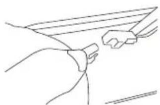
Lighting
LIGHT REPLACEMENT
- Switch off the extractor hood and isolate the extractor hood by pulling out the mains plug or switching off the fuse.
- Remove the grease filter.
- Remove the light by levering its fitting from the hood body(this may require pressure or force to be applied).
| Max Power | Voltage Picture | Lamp Cap ILCOS D code | |||
| Self-ballasted LED modules | 1.5W 220V-240V~ | 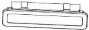 Square/Diameter:33.2mmx120mm Square/Diameter:33.2mmx120mm | -- | DBS-1.5-H-33.2/120 | |
natural_image
Technical line drawing of a mechanical component or housing (no text or symbols)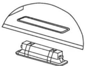
natural_image
Technical line drawing of a mechanical component with a curved top and rectangular base (no text or symbols)- Disconnect the connector of the light.
- Replace the light with a new one of the same type, making sure that you connect the light with the light cable correctly.
- Reinstall the light back to the hood body.
natural_image
Line drawing of a hand holding a rectangular object, possibly a device or panel (no text or symbols)TROUBLESHOOTING
| Possible reason SolutionProblem | ||
| Light on, but motor does not work | The blades are blocked. | Check the blades |
| The capacitor is damaged. | Replace capacitor. | |
| The motor is damaged. | Replace motor. | |
| The internal wiring of motor is cut off/disconnected. An unpleasant smell may be produced. | Replace motor. | |
| Both light andmotor do notwork | Apart from the above mentioned, check the following: | |
| Light damaged. Replace lights. | ||
| Power cord loose. Connect the wires as the electric diagram. | ||
| Oil leakage | Outlet and the air ventilation entrance are not tightly sealed. | Take down the outlet and seal with glue. |
| Vibration | The blade, if damaged, can cause vibrating. | Replace the blade. |
| The motor is not tightly fastened. | Fasten the motor tightly. | |
| The cooker hood is not tightly fixed. | Fixed the cooker hood tightly. | |
| Insufficient suction | The distance between the cooker hood and the cooker top is too large. | Readjust the distance. |
| Too much ventilation from open doors or windows. | Choose a new place to install the appliance or close some doors / windows. | |
| The machine inclines | The fixing screws are not tight enough. | Tighten the fixing screw and make it horizontal. |
| The hanging screws are not tightenough | Tighten the hanging screw and make it horizontal. | |
TRADEMARKS, COPYRIGHTS AND LEGAL STATEMENT
Midea logo, word marks, trade name, trade dress and all versions thereof are valuable assets of Midea Group and/or its affiliates ("Midea"), to which Midea owns trademarks, copyrights and other intellectual property rights, and all goodwill derived from using any part of an Midea trademark. Use of Midea trademark for commercial purposes without the prior written consent of Midea may constitute trademark infringement or unfair competition in violation of relevant laws.
This manual is created by Midea and Midea reserves all copyrights thereof. No entity or individual may use, duplicate, modify, distribute in whole or in part this manual, or bundle or sell with other products without the prior written consent of Midea.
All the described functions and instructions were up to date at the time of printing this manual. However, the actual product may vary due to improved functions and designs.
DISPOSAL AND RECYCLING
Important instructions for environment
Compliance with the WEEE Directive and Disposing of the Waster Product: This product complies with EU WEEE Directive (2012/19/EU). This product bears a classification symbol for waster electrical and electronic equipment (WEEE).
This symbol indicates that this product shall not be disposed with other household wastes at the end of its service life. Used device must be returned to official collection point for recycling of electrical electronic devices. To find these collection systems please contact to your local authorities or retailer where the product was purchased. Each household performs important role in recovering and recycling of old appliance. Appropriate disposal of used appliance helps prevent potential negative consequences for the environment and human health.
natural_image
Symbol of a trash bin crossed with a diagonal line and a horizontal line, representing no waste or elimination (no text or labels)Compliance with RoHS Directive
The product you have purchased complies with EU RoHS Directive (2011/65/EU). It does not contain harmful and prohibited materials specified in the Directive.
Package information
Packaging materials of the product are manufactured from recyclable materials in accordance with our National Environment Regulations. Do not dispose of the packaging materials together with the domestic or other wastes. Take them to the packaging material collection points designated by the local authorities.

natural_image
Recycling symbol with three chasing arrows forming a triangle (no text or labels)DATA PROTECTION NOTICE
For the provision of the services agreed with the customer,
we agree to comply without restriction with all stipulations of applicable data protection law, in line with agreed countries within which services to the customer will be delivered, as well as, where applicable, the EU General Data Protection Regulation (GDPR).
Generally, our data processing is to fulfil our obligation under contract with you and for product safety reasons, to safeguard your rights in connection with warranty and product registration questions. In some cases, but only if appropriate data protection is ensured, personal data might be transferred to recipients located outside of the European Economic Area.
Further information are provided on request. You can contact our Data Protection Officer via MideaDPO@midea.com. To exercise your rights such as right to object your personal date being processed for direct marketing purposes, please contact us via MideaDPO@midea.com. To find further information, please follow the QR Code.
PRODUCT FICHE FOR DOMESTIC RANGE HOOD
According to Delegated Regulation (EU) No. 65/2014
| Supplier's name or trade mark | Midea |
| Model name / identifier | MH60J76M21B/MH90J76M21BB |
| Annual Energy Consumption (AEChood) | 12,3 kWh/year |
| Energy Efficiency class (A+++ to D) | A+ |
| Fluid Dynamic Efficiency (FDE hood) | 26,4 |
| Fluid Dynamic Efficiency class (A to G) | B |
| Lighting Efficiency (LE hood) | 30 Lux / Watt |
| Lighting Efficiency class (A to G) | A |
| Grease Filtering Efficiency | 75,7 % |
| Grease Filtering Efficiency class (A to G) | C |
| Air flow in normal use (min. speed): | 209,7 m3/h |
| Air flow in normal use (ax . speed): | 420,6 m3/h |
| Air fhsive (or boost setting): Exterior | / |
| Airborne acoustical A-weighted sound power emissions (min. speed) | 50 dB |
| Airborne acoustical A-weighted sound power emissions (max. speed) | 60 dB |
| Airborne acoustical A-weighted sound power emissions (intensive or boost setting) | / |
| Power consumption in off mode (Po) | 0.4W |
| Power consumption in standby mode (Ps) | 0.49W |

make yourself at home
natural_image
Simple line drawing of a rectangular block with two inner rounded rectangles, no text or symbols present.Hotte de cuisinière
MANUEL D'UTILISATEUR
MH90J76M21BB
MH60J76M21B
LETTRE DE REMERCIEMENT
INSTALLATION DU PRODUIT ....07
INSTRUCTIONS D'OPÉRATION 11
NETTOYAGE ET ENTRETIEN 11
DÉPANNAGE ....13
MARQUES, DROITS D'AUTEUR ET DÉCLARATION LÉGALE ....14
ÉLIMINATION ET RECYCLAGE 14
AVIS DE PROTECTION DES DONNÉES 15
FICHE DU PRODUIT POUR LA HOTTE DOMESTIQUE .. 16
CONSIGNES DE SÉCURITÉ
Utilisation prévue
unité : mm
INSTALLATION DU PRODUIT
natural_image
Simple line drawing of a rectangular box with a smaller inner rectangle (no text or symbols)
natural_image
Simple line drawing of a rectangular frame with a small protrusion on top (no text or symbols)Correct Incorrect
natural_image
Technical diagram of a mechanical ventilation system with fan and pump components (no text or labels)natural_image
Diagram showing a device assembly before and after transformation, with no visible text or symbols.natural_image
Technical diagram showing a mechanical assembly with a dashed circular inset view of a cabinet and a cylindrical component (no text or symbols)INSTRUCTIONS D'OPÉRATION
natural_image
Illustration of a hand holding a tablet device with a downward arrow, enclosed in a circular frame (no text or symbols)natural_image
Line drawing of a mechanical component with no visible text or symbols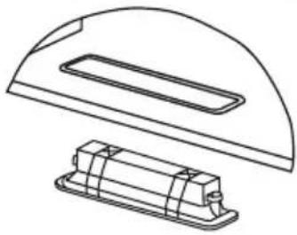
natural_image
Technical line drawing of a mechanical component with a curved top and rectangular base (no text or symbols)natural_image
Line drawing of a hand holding a small object, possibly a tool or device, with no visible text or symbols.DÉPANNAGE
natural_image
Symbol of a trash bin crossed with a diagonal line and a blank rectangular block below (no text or labels)natural_image
Recycling symbol with three chasing arrows forming a triangle (no text or labels)AVIS DE PROTECTION DES DONNÉES
make yourself at home

www.midea.com
16173000A24559

- BENUTZERHANDBUCH
- PRODUKTINSTALLATION
- Richtig Falsch
- Verbindungen
- Oberer dekorativer Schornstein
- BETRIEBSANLEITUNG
- FEHLERBEHEBUNG
- DATENSCHUTZHINWEIS
- USER MANUAL
- THANK YOU LETTER
- CONTENTS
- SAFETY INSTRUCTIONS
- Intended Use
- Explanation of Symbols
- Danger
- Warning of electrical voltage
- Warning
- Caution
- Attention
- Observe instructions
- PRODUCT OVERVIEW
- PRODUCT INSTALLATION
- Wall Drilling And Bracket Fixing
- As a first step, proceed with the following drawings:
- Mark Points:
- Fix the brackets (Optional):
- Hook The Hood Body
- Choose a venting mode
- Connections
- Ducted Version Air Exhaust System
- The chimney can only be installed with exhausting hood.
- Lower Decorative Chimney
- Upper Decorative Chimney
- OPERATION INSTRUCTIONS
- Speed Adjustment. (For Some Models)
- CLEANING AND MAINTENANCE
- Grease Filters
- CLEANING METAL SELF-SUPPORTING GREASE FILTERS
- Activated Charcoal Filter (Recirculation Version)
- Replacing The Activated Charcoal Filter
- Lighting
- LIGHT REPLACEMENT
- TROUBLESHOOTING
- TRADEMARKS, COPYRIGHTS AND LEGAL STATEMENT
- DISPOSAL AND RECYCLING
- Important instructions for environment
- Compliance with RoHS Directive
- Package information
- DATA PROTECTION NOTICE
- PRODUCT FICHE FOR DOMESTIC RANGE HOOD
- MANUEL D'UTILISATEUR
- LETTRE DE REMERCIEMENT
- CONSIGNES DE SÉCURITÉ
- Utilisation prévue
- INSTALLATION DU PRODUIT
- Correct Incorrect
- INSTRUCTIONS D'OPÉRATION
- DÉPANNAGE
- AVIS DE PROTECTION DES DONNÉES
Brand : MIDEA
Model : MH60J76M21B
Category : Basket