
HEPD80 - Electrical assembly kit SCHNEIDER - Free user manual and instructions
Find the device manual for free HEPD80 SCHNEIDER in PDF.

| Product Type | Flush mount kit for surge protective device (SPD) |
| Brand | Schneider |
| Model | HEPD80 |
| Use | Mounting an SPD in an electrical distribution panel |
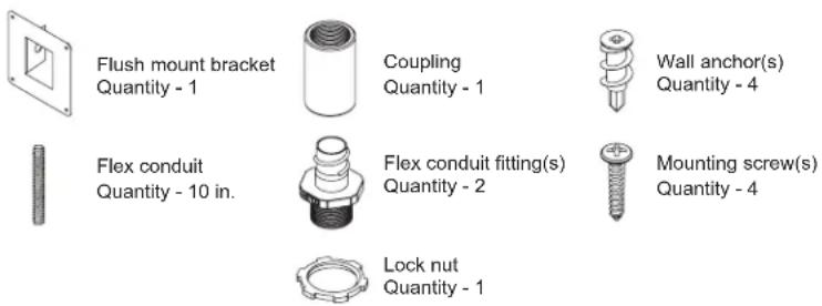
| Kit Contents | Flush mount bracket (1), coupler (1), wall anchors (4), 10-inch flexible conduit (1), conduit fittings (2), mounting screws (4), lock nut (1) |
| Material | Plastic and metal |
| Bracket dimensions | Approximately 100 x 100 x 50 mm |
| Weight | Approximately 0.3 kg |
| Power supply | Not applicable (mechanical kit) |
| Rated voltage | Compatible with SPD up to 240 V (depending on mounted SPD) |
| Installation | By qualified personnel, cut off power before any intervention |
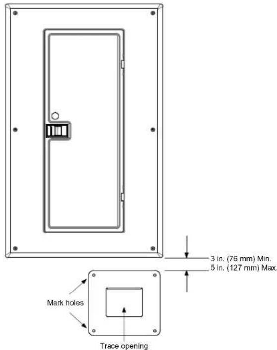
| Offset distance | Between 76 mm (3 in) and 127 mm (5 in) below the distribution center |
| Flexible conduit | Length adapted to offset distance, cut to measurement |
| Main functions | SPD mounting, cable routing, grounding |
| Maintenance | Periodically check the green LED indicators of the SPD |
| Cleaning | Wipe with a dry cloth |
| Safety | Grounding mandatory, use a voltage detector, comply with NFPA 70E / CSA Z462 standards |
| Spare parts | Mounting bracket, coupler, anchors, screws - available from Schneider |
| Repairability | Not user-serviceable, replace kit if defective |
| Warranty | 2 years (estimate) |
Frequently Asked Questions - HEPD80 SCHNEIDER
User questions about HEPD80 SCHNEIDER
0 question about this device. Answer the ones you know or ask your own.
Ask a new question about this device
Download the instructions for your Electrical assembly kit in PDF format for free! Find your manual HEPD80 - SCHNEIDER and take your electronic device back in hand. On this page are published all the documents necessary for the use of your device. HEPD80 by SCHNEIDER.
USER MANUAL HEPD80 SCHNEIDER
HEPD80 Flush Mounting Kit
Retain for future use.
Precautions
DANGER
HAZARD OF ELECTRIC SHOCK, EXPLOSION, OR ARC FLASH
- Apply appropriate personal protective equipment (PPE) and follow safe electrical work practices. See NFPA 70E or CSA Z462.
- This equipment must only be installed and serviced by qualified electrical personnel.
- Turn off all power supplying this equipment before working on or inside equipment.
- Always use a properly rated voltage sensing device to confirm power is off.
- Replace all devices, doors and covers before turning on power to this equipment.
- This equipment must be effectively grounded per all applicable codes. Use an equipment-grounding conductor to connect this equipment to the power system ground.
Failure to follow these instructions will result in death or serious injury.
Kit Contents
Installation
Find a suitable location for the HEPD80 and flush mount kit. These locations are typically above or below the load center/power panel (see Figure 1). The mounting location should be free from obstructions in the wall that would prevent the installation of conductors, e.g. stud(s) or other obstructions.
- Turn off all power supplying this equipment before working on or inside any enclosure containing this equipment.
- Confirm the SPD voltage rating and configuration is the same as the system voltage and power system configuration to which it will be connected.
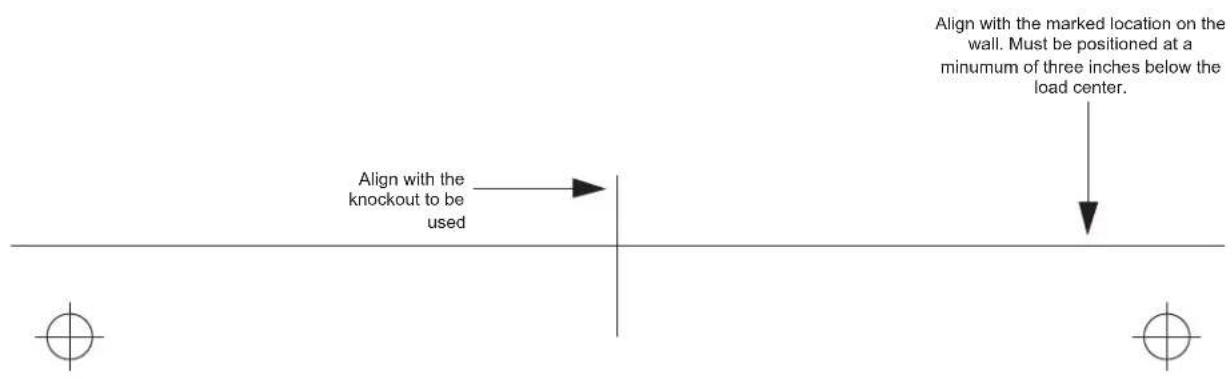
- Place the cut-out template provided flat against the wall positioned at a minimum of three, to a maximum of, five inches below the bottom of the load center and properly aligned with the available knockout. See Figure 1.
- Mark the locations of the four mounting holes and the area of the wall to be cut out. See Figure 1.
Figure 1: Device Preparation
- Using a saw or a knife, cut out an opening for the Surge Protective Device (SPD).
- Install the four wall anchors into the marked mounting holes. (No drilling is required).
- Remove the knockout in the bottom of the load center that best fits the location of the SPD. See Figure 2.
Figure 2: Remove Knockout
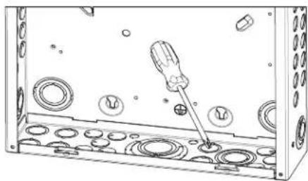
natural_image
Technical line drawing of a screwdriver inserted into a housing with circular components (no text or symbols)- Straighten the SPD wire coil (A), as shown in Figure 3.
- Remove the conduit locking nut (B).
Figure 3: Device Preparation
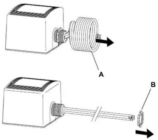
natural_image
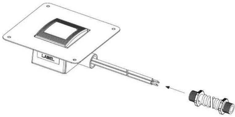
Technical illustration of two mechanical components labeled A and B, showing assembly or assembly details (no text or symbols beyond labels)- Thread the ends of the wires through the mount bracket hole (C) and the coupling provided, as shown in Figure 4.
Figure 4: Threading the Bracket Hole

- Hand tighten the coupling onto the threaded nipple of the SPD securing the flush mount bracket in place. See Figure 5.
Figure 5: Coupling Installation
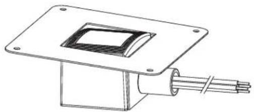
natural_image
Technical line drawing of a mechanical assembly with a square plate and coiled cable (no text or symbols)- Carefully flex the bracket onto the SPD, as shown in Figure 6.
Figure 6: Bracket Flexing
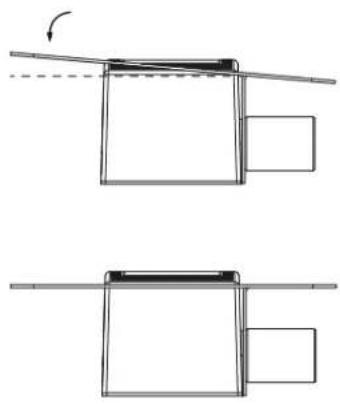
natural_image
Diagram showing two mechanical assembly steps with no visible text or symbols- Cut the flexible conduit to the appropriate length to accommodate the installation.
Note: The length of conduit will be the same as the offset distance from the bottom of the load center, as identified in step 1. See Figure 1.
Example: If the offset distance from the bottom of the load center is three inches, the conduit length should also be three inches.
- Install the two flex conduit fittings onto each end of the flex conduit.
See Figure 7.
Figure 7: Coupling Installation
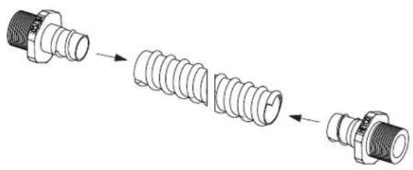
natural_image
Diagram showing a sequence of three types of threaded connectors (no text or symbols present)- Thread the flex conduit assembly over the SPD wires and attach to the coupling of the SPD assembly.
Note: Finger tighten the conduit coupling and tighten for an additional 1/4 turn. See Figure 8.
Figure 8: Coupling Installation
natural_image
Technical line drawing of a microchip mounted on a base with connectors, showing no text or symbols.- Thread the wires and SPD assembly through the hole in the wall and through the knockout of the load center. Slip the lock nut over the wires and secure the conduit in place, as shown in Figure 9.
- Secure the mounting bracket to the wall using the four screws provided. See Figure 9.
Figure 9: Attach the Conduit
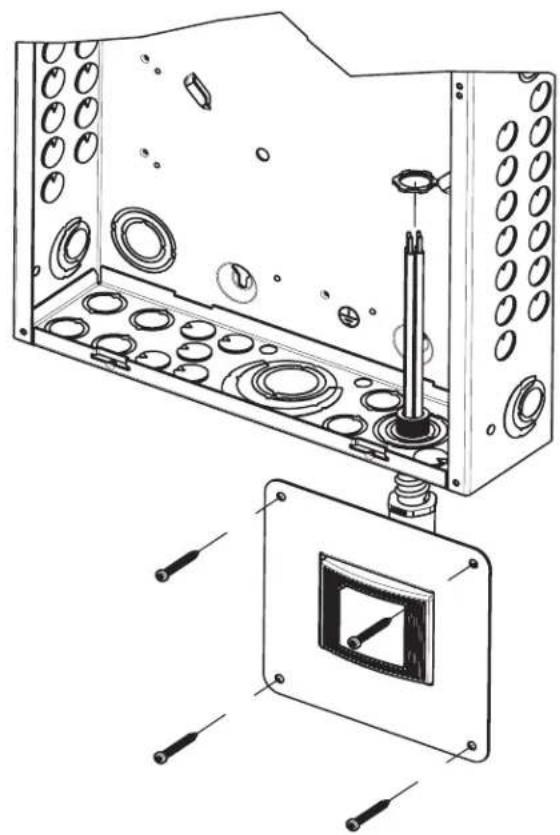
natural_image
Technical line drawing of a mechanical assembly with internal components and mounting holes (no text or symbols)- Connect the ground wire from the SPD to the grounding lug located in the power panel. See Figures 10 and 11.
- Connect the SPD black wires now located in the power panel to a 20 amp two-pole circuit breaker. See Figures 10 and 11.
NOTE: Confirm that the two-pole circuit breaker is in the OFF position prior to installing the wires. - Connect the SPD white wire now located in the power panel to the neutral bus. See Figures 10 and 11.
Figure 10: HEPD Layout
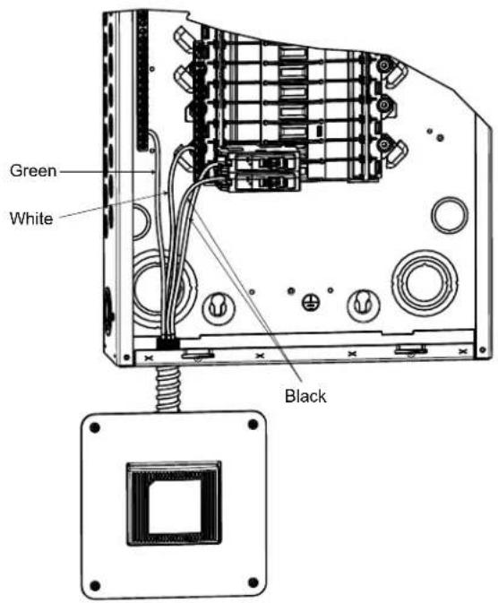
Figure 11: Typical AC Surge Module Wiring Connection Diagrams
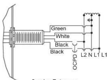
Service Entrance without Grounding Bar 120/240 V 10, 3-Wire Circuit
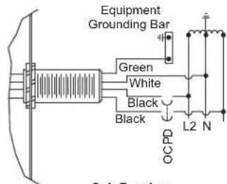
Sub-Panel or Service Entrance with Grounding Bar 120/240 V 1∅, 3-Wire Circuit
Operating and Testing 1. Turn on the two-pole circuit breaker feeding the SPD.
- Replace all devices, doors and covers.
- Restore power to the power panel. If the electrical and grounding sections are installed correctly the green lights on the AC section of the SPD will be on. If neither of the lights are on, turn off the power and review all steps of 'mounting'.
- Periodically check the green lights on the AC surge suppression device to ensure that they are illuminated. If one or both the green lights go out, it indicates that AC power or suppression has been lost.
WALL CUTOUT WINDOW

