
BT-BD 1625 D - Drill EINHELL - Free user manual and instructions
Find the device manual for free BT-BD 1625 D EINHELL in PDF.

| Product type | Column drill |
| Brand | Einhell |
| Model | BT-BD 1625 D |
| Power supply | 230 V ~ 50 Hz |
| Rated power | 700 W |
| Motor speed | 1400 min⁻¹ |
| Speed range | 210 - 2220 min⁻¹ |
| Operating mode | S2 15 min (intermittent duty) |
| Chuck capacity | 3 - 16 mm |
| Chuck type | Quick-release chuck |
| Chuck mount | B 16 |
| Spindle taper | MK2 |
| Spindle axis to frame distance | 169 mm |
| Table dimensions | 260 x 260 mm |
| Table tilt | 45° / 0° / 45° |
| Drilling depth | 80 mm |
| Column diameter | 70 mm |
| Total height | Approx. 1590 mm |
| Dimensions (L x D) | 450 x 265 mm |
| Weight | 60 kg |
| Sound pressure level | 61.5 dB(A) |
| Sound power level | 74.5 dB(A) |
| Main functions | Drilling, chamfering, centering drilling |
| Speed adjustment | By moving V-belt |
| Depth stop | Adjustable graduated ring |
| Protection device | Foldable chip guard |
| Safety switch | Safety switch on belt cover |
| Maintenance | Regular cleaning, greasing of bare parts |
| Spare parts | Available via ISC GmbH |
| Repairability | Repair by qualified electrician recommended |
Frequently Asked Questions - BT-BD 1625 D EINHELL
User questions about BT-BD 1625 D EINHELL
0 question about this device. Answer the ones you know or ask your own.
Ask a new question about this device
Download the instructions for your Drill in PDF format for free! Find your manual BT-BD 1625 D - EINHELL and take your electronic device back in hand. On this page are published all the documents necessary for the use of your device. BT-BD 1625 D by EINHELL.
USER MANUAL BT-BD 1625 D EINHELL
3
natural_image
Close-up of a mechanical joint or pipe fitting with numbered annotations (26 and 30) indicating specific components, no readable text or symbols beyond labels.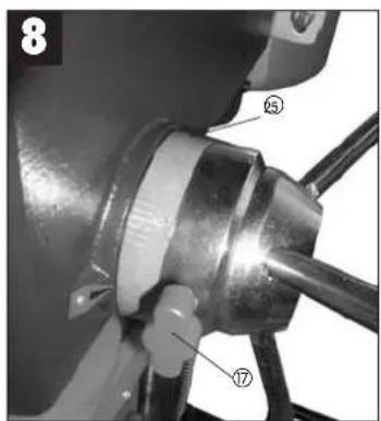
bar
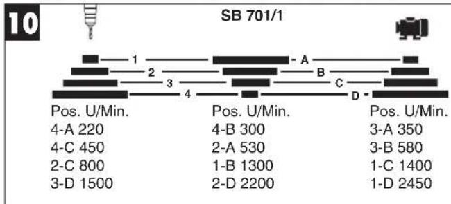
SB 701/1 | Category | Position | Value | |---|---|---| | Pos. U/Min. | 4-A 220 | 2 | | Pos. U/Min. | 4-B 300 | 4 | | Pos. U/Min. | 3-A 350 | 3 | | Pos. U/Min. | 3-B 580 | 3 | | Pos. U/Min. | 1-C 1400 | 1 | | Pos. U/Min. | 1-D 2450 | 1 | | Pos. U/Min. | 2-A 530 | 2 | | Pos. U/Min. | 1-B 1300 | 1 | | Pos. U/Min. | 2-D 2200 | 2 | | Pos. U/Min. | 3-D 1500 | 3 | | Pos. U/Min. | 4-C 450 | 4 | | Pos. U/Min. | 2-C 800 | 2 | | Pos. U/Min. | 3-D 1500 | 3 | The chart displays a single bar for the 'Pos. U/Min.' category, which is divided into three segments: (1) a small bar at position 1, (2) a medium bar at position 2, and (3) a large bar at position 3, with the last bar at position D being the longest segment. The label 'SB 701/1' appears in the top left corner.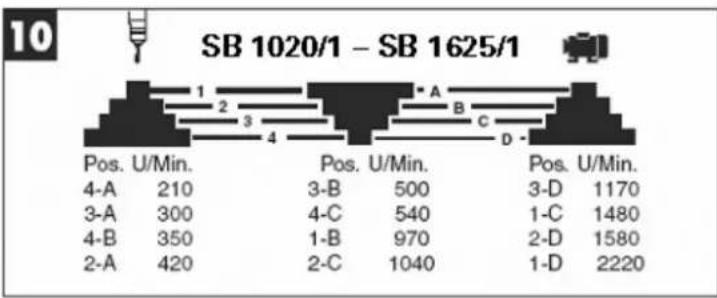
other
SB 1020/1 – SB 1625/1 | Position | U/Min. | Position | U/Min. | Position | U/Min. | | :--- | :--- | :--- | :--- | :--- | :--- | | 4-A | 210 | 3-B | 500 | 3-D | 1170 | | 3-A | 300 | 4-C | 540 | 1-C | 1480 | | 4-B | 350 | 1-B | 970 | 2-D | 1580 | | 2-A | 420 | 2-C | 1040 | 1-D | 2220 |
natural_image
Close-up of a hand using a hammer to press a mechanical setup with a clamping device (no visible text or symbols)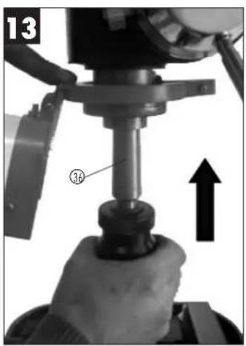
natural_image
Close-up of a hand operating a mechanical press or drill bit with a numbered component (no visible text or symbols)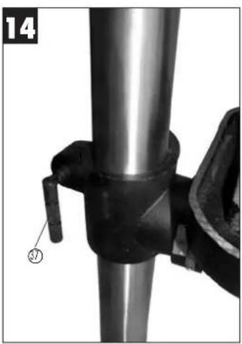
natural_image
Close-up of a metal pipe joint with a clamp and valve, no visible text or symbols6
● Bohrfutterschlüssel
1.0. Layout (Fig. 1/2)
-
Machine base
-
Pillar
-
Fixing screw
-
Drill table
-
Drill table clamp shaft
-
Machine head
7 V-belt
8 Motor
9 Grin knobs
10 Drill chuck
11 Spindle
12 Mounting holes
-
Hinged chip guard
-
Depth stop (only SB 401/1)
-
Tightening screw
-
Screw
-
Clamping screw (only SB 501/1)
-
On switch
-
Off switch
-
Grub screw
-
Crank
2.0. Items supplied
- Pillar drill
- drill chuck
- Drill chuck key
● Hinged chip guard
• Vise
3.0. Proper use
This pillar drill is designed for drilling metal, plastic, wood and similar materials. It is intended for use in the private sector only.
Food and harmful materials may not be processed with the machine. The drill chuck is only designed for use with drill bits and tools with a shaft diameter of 3 to 16 mm, and for cylindrical tool shanks. In addition, tools with tapered shanks (see the technical data for the respective version in Chapter 9) may also be used, as described in Chapter 7.5. The machine is intended for use by adults only. It is designed for temporary operation (S2 15 min). Any use of the machine other than that which is cited in these operating instructions releases the manufacturer from all liability and renders every warranty claim null and void.
4.0. Safety information
The pillar drill was designed in such a way so as to all but eliminate potential hazards when the machine is properly used. However, there are a few safety
precautions to observe in order to ensure that all residual hazards are ruled out.
Ensure proper voltage
The voltage must comply with the specifications on the rating plate.
Use a socket-outlet with earthing contact
The device may only be operated from an outlet with the properly installed earthing contact.
Extension cable
The cord cross section of an extension cable must measure at least 1.5 mm ^2 . Always completely unwind a cable reel prior to use. Check the cable for defects.
Protection against electrical shock
Keep the device away from moisture. The device must neither be damp nor be operated in a humid environment. Prior to every use, check the device and the mains cable with plug for damage. Avoid bodily contact with earthed parts e.g. pipes, hot elements, etc.
Protection against fire and explosion
There are spark producing components inside the device. Do not use the device in the vicinity of combustible liquids or gases. Otherwise there is a risk of fire or explosion.
Handle the device with care
Do not use the cable to pull the plug out of the socket. Protect the cable from heat, oil and sharp edges. Keep your tools sharp and clean so that you can work efficiently and safely. Follow the maintenance regulations and the instructions for changing tools.
Wear suitable work clothes and personal protection equipment
Loose clothing is not suitable, as it can be caught by moving parts, causing you to become entangled. Wear a hair net if you have long hair. As a general rule, jewelry should not be worn when working with machine tools. Ensure that you wear safety goggles. Not doing so could result in eye injury.
Keep your work area neat and tidy
Disorder in the work area can easily lead to accidents. Do not leave any tools, objects, or cable in the direct vicinity of the work area, as this poses a tripping hazard! Ensure that there is sufficient lighting.
GB
Watch out for other persons
Watch out for other persons (especially children) when using the device, and keep them away from your work area. Do not let anyone touch the device or the power cable.
Store the tools in a safe location
Store unused devices in a dry, locked location that is out of the reach of children.
Avoid overloading the device
Operate the device only within the specified output range. Do not use any low-powered machines for heavy duty work. Do not use tools to perform work for which they were not intended.
Maintain a steady foothold
Ensure that you maintain a steady foothold while working. Avoid abnormal body positions and always keep your balance.
Pull out the mains plug
Pull out the mains plug when not using the tool, prior to maintenance, and when changing the drill bit.
Avoid unintentional start-up
Ensure that switch is turned off when plugging the plug into the socket.
Keep an eye on your work
Always keep an eye on your machine and the object you are working on. Never use the machine when you are not concentrating or are distracted. Never use the machine when you are under the influence of alcohol or are taking medication.
Check the tool for damage
Before using the tool, safety devices and any slightly damaged parts must be carefully checked to ensure that they are in good working order. Visually examine the tool's power cable on a regular basis. All parts must be correctly assembled and meet all the conditions required to ensure proper operation. Unless otherwise specified in the operating instructions, any damaged safety devices and parts must be properly repaired or replaced by a professionally recognized workshop. Never use tools with defective On/Off switches.
Warning! Using any plug-in tools and accessories other than those specified in these operating instructions can lead to injury.
Maximum workpiece size
Workpieces (max. 20 x 20 cm) may only be processed if they can be clamped securely on the drill table or in the vise.
Now, please read and follow all steps and procedures included in the operating instructions.
5.0. Installation
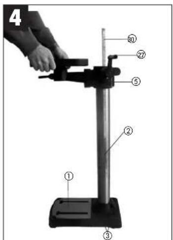
5.1. Assembling the machine (Figs. 1/4/5)
- Place the base plate (1) in the desired position.
- Fasten the pillar (2) with flange using the supplied screws (3).
- Insert the screw gear in the drill table support.
- Then insert the gear rack (30) in the drill table support (5) with the teeth facing the screw gear (identical projection).
- Now slip these parts together over the pillar (2). In doing so, make sure that the gear rack is correctly seated in the teeth of the screw gear.
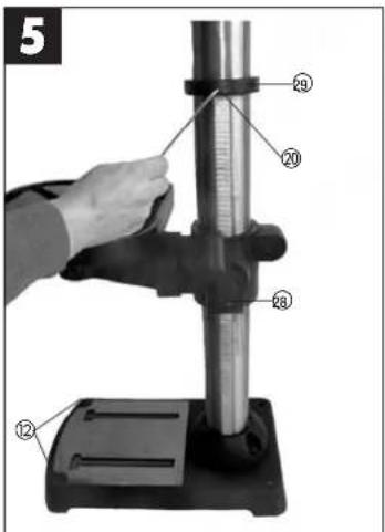
● To secure the gear rack at the top end, slip on the guide sleeve (29) over the pillar and fasten with the screw. - You can now fit the table and clamp in place with the clamping lever. Following this, fit the crank (27) and fasten tightly with the screw (28).
- Finally, fit the complete bit head to the pillar. Align the head so that it is horizontal to the base plate and fasten it in position with the screws (35).
● Screw the 3 supplied handles (9) in the handle mounts. - Before you mount the drill chuck with the MK shank, check that both parts are clean. Insert the taper mandrel in the taper of the drill chuck with a powerful jolt. Then insert the taper in the spindle (Fig. 13)
- Check the tension of the V-belt regularly before use (Fig. 9).
Important: All bare parts are greased in order to protect them from corrosion. Before mounting the drill chuck (10) onto the spindle (11), both parts must be completely degreased using an environmentally friendly solvent. This ensures optimal transmission of power.
5.2. Installing the machine (Figs. 4/5)
Before you use the drill for the first time it must be permanently fixed in position. Use both mounting holes (12) in the base plate to do this. Ensure that the machine is freely accessible for operation, adjustment and maintenance. Important: The fixing screws may only be tightened
GB
to a point where they do not distort or deform the base plate. Excessive tension can lead to fracture.
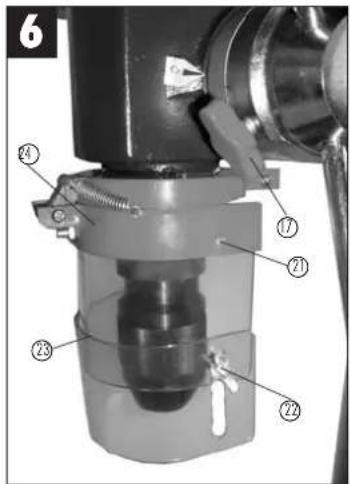
5.3. Hinged chip guard (Fig. 5)
Unscrew the three recessed head screws (21). Push the transparent cover (23) into the groove of the red mounting frame (24) and fasten it again with the recessed head screws (21).
The height of the cover (23) is infinitely adjustable and can be locked using the two thumb screws (22). The chip guard (13) can be flipped up to enable bits to be changed.
5.4. Prior to starting
Ensure that the voltage of the mains supply complies with the specifications on the rating plate. Connect the machine only to a socket with the properly installed earthing contact.
The table drill is equipped with a no-volt trip that is designed to protect the operator from an undesired restart following a drop in voltage. Should this occur, the machine must be manually restarted.
6.0. Operation

Wear suitable, protective clothing (i.e. rugged and tight-fitting) when working with the table drill.

Always wear safety goggles!

Long hair should always be bound back with a hair net or a cap!
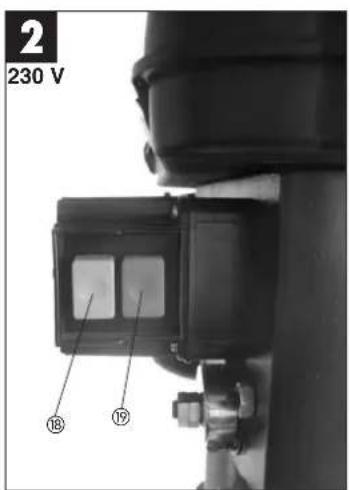
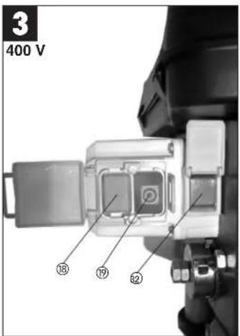
6.1. General (Fig. 3)
To switch on the machine, push in the green On button "I". (18); the machine starts up. To switch off, press the red Off button "O" (19); the device shuts down. Three-phase a.c. pillar drills come with forward/reverse functions. Only ever actuate the switch for changing the direction of rotation (32) with the motor at a standstill!
Ensure that you do not overload the device. If the sound of the motor drops in pitch during operation, it is being overloaded.
Do not overload the device to the point where the motor comes to a standstill.
It is designed for temporary operation (S2 15 min). The machine may only be used under full load for a maximum of 15 minutes, after which the machine must be shut down until the motor winding has cooled down to room temperature. This prevents the
motor from overheating.
6.2. Inserting the tool (Fig. 1/2)
Make sure that the power plug is removed from the socket-outlet before changing tools. Only cylindrical tools with the stipulated maximum shaft diameter may be clamped in the scroll chuck (10). Only use a tool that is sharp and free of defects. Do not use tools whose shaft is damaged or which are deformed or flawed in any other way. Use only accessories and attachments that are specified in the operating instructions or have been approved by the manufacturer.
6.3. Handling the scroll chuck (SB 701/1)
Your pillar drill SB 701/1 is equipped with a gear-toothed drill chuck. T insert a drill bit, flip up the chip guard (13), insert the drill bit, then tighten down the drill chuck using the supplied chuck key. Pull out the chuck key. Ensure that the clamped in tool is firmly seated.
Important! Do not leave the chuck key in the clamp hole. Doing so will cause the chuck key to rapidly shoot out, which could cause injury.
6.4. Handling the quick-change drill chuck (SB 1020/1 and SB 1625/1)
The pillar drills SB 1020/1 and SB 1625/1 are equipped with a quick-change drill chuck. This enables tools to be changed without the need for an additional chuck key. To do so, insert the tool in the quick-change drill chuck and tighten by hand.
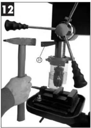
6.5. Use of tools with tapered shanks (Abb. 12/13)
The pillar drill comes with a spindle taper.
To use tools with tapered shanks (MK2 or MK3 mount, subject to version), proceed as follows:
- Move the drill chuck to the lower position.
- Eject the tapered shank using the supplied drill drift (31), taking care as you do so to ensure that the tool does not land on the floor.
- Insert the new tool with tapered shank (36) in the spindle taper with a jolt and then check that the tool is correctly seated.
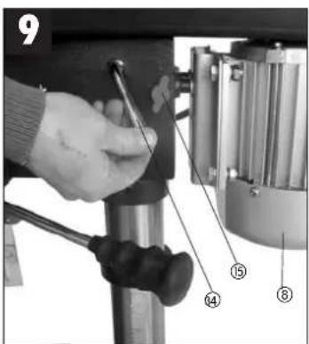
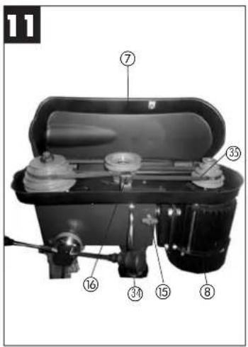
6.6. Setting the speed (Fig. 1/2/7/8/10/11)
First switch the machine off, then pull out the mains plug.
The various spindle speeds can be set by moving the V-belt.
Proceed as follows:
- Remove the screw (16) in order to open the V-belt cover (7).
- Slacken the tightening screw (15) and push the motor (8) in the direction of the machine head.
- Move the V-belt to the desired position.
GB
- Please refer to table 6.12 for the corresponding speeds 6.12.
● To tighten the V-belt, press the clamping lever (34) in the direction of the motor and re-tighten the fixing screw (13). - Close the V-belt cover and screw down using the screw (16). The V-belt cover (7) must always be locked tight, as the machine is equipped with a safety switch that only allows the machine to be turned on when the V-belt cover (7) is closed.
Caution! Never let the pillar drill run when the V-belt cover is open. Always pull the mains plug before opening the cover. Never touch the V-belt when it is rotating.
6.7 Drill depth stop point SB 501/1 (Fig. 12)
The drilling spindle has a swiveling scale ring for setting the drill depth. Only adjust the setting when the machine is at a standstill.
-Lower the drilling spindle (11) until the tip of the drill bit touches the workpiece.
-Slacken the clamping screw (17) and turn the scale ring (25) forwards until it stops.
-Turn the scale ring (25) back to the desired drill depth, then lock this setting into place using the clamping screw (17).
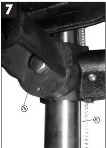
6.8. Setting the angle of the drill table (Fig. 7)
Slacken the carriage bolt (26) under the drill table (4).
Set the drill table (4) to the desired angle. Tighten down the carriage bolt (26) in order to lock the drill table (4) into this position.
6.9. Setting the height of the drill table (Fig. 1/4)
Slacken the tightening screw (37). Set the drill table to the desired position with the help of the hand crank (27). Screw the tightening screw (37) back down again.
6.10 Clamping the workpiece (Fig. 1)
As a general rule, use a machine vice or another suitable clamping device to secure a workpiece in position. Never hold the workpiece in place with your hand! When drilling, the workpiece should be able to travel on the drill table (4) for self-centering purposes. Ensure that the workpiece cannot rotate. This is best achieved by placing the workpiece /machine vice on a sturdy block. Caution! Sheet metal parts must be clamped in to prevent them from being torn up. Properly set the height and angle of the drill table for each workpiece. There must be enough distance between the upper edge of the workpiece and the tip of the drill bit.
6.11. Drilling wood
Please note that sawdust must be properly evacuated when working with wood, as it can pose a health hazard. Ensure that you wear a suitable dust mask when performing work that generates dust.
6.12. Working speeds
Ensure that you drill at the proper speed. Drill speed is dependent on the diameter of the drill bit and the material in question.
The table below acts as a guide for selecting the proper speed for various materials.
Note: The drill speeds specified are merely suggested values.
| Drill bit ∅ Cast iron Steel Iron Aluminium Bronze |
| 3 2500 1600 2230 9500 8000 |
| 4 1900 1200 1680 7200 6000 |
| 5 1530 955 1340 5700 4800 |
| 6 1270 800 1100 4800 4000 |
| 7 1090 680 960 4100 3400 |
| 8 960 600 840 3600 3000 |
| 9 850 530 740 3200 2650 |
| 10 765 480 670 2800 2400 |
| 11 700 435 610 2600 2170 |
| 12 640 400 580 2400 2000 |
| 13 590 370 515 2200 1840 |
| 14 545 340 480 2000 1700 |
| 16 480 300 420 1800 1500 |
| 18 425 265 370 1600 1300 |
| 20 360 240 335 1400 1200 |
| 22 350 220 305 1300 1100 |
| 25 305 190 270 1150 950 |
6.13. Countersinking and center-drilling
With this table drill, you can also countersink and center-drill. Please observe that countersinking should be performed at the lowest speed, while a high speed is required for center-drilling.
7.0. Care and maintenance
The table drill is to a large extent maintenance-free. Keep the device clean.
Pull out the mains plug before doing any cleaning and maintenance work on the machine.
Do not use any harsh, abrasive cleaning solvents. Ensure that no liquid seeps into the device.
Regrease all bare parts when the work is finished. The drill pillar, blank parts of the column, and the drill table especially should be regreased at regular
intervals. Use a standard, acid-free lubricating grease to do this.
Caution: Do not use your household refuse bin as a receptacle for oil and grease-soaked cleaning rags or grease and oil sludge. Dispose of these toxic materials in an environmentally-friendly fashion. Regularly check and clean the ventilation holes. Store the device in a dry room. Should the device become damaged, do not try to repair it yourself; leave this work to the hands of a qualified electrical technician.
8.0. Ordering replacement parts
Replacement parts can be ordered through ISC GmbH (see the warranty declaration for the
address). The following information should be
provided when placing an order:
● Model/type of device
- Item number of device
• LD number of device
● Number of the required replacement part
9.0. Technical data SB 701/1 SB 1020/1W SB 1020/1D SB 1625/1W \$B 1625/1 D
| Nominal input voltage 230V | -/-50 Hz 230V | -/-50 Hz 400V | -/-50 Hz 230V | -/-50 Hz 400V | -/-50 Hz | |
| Power rating 630 Watt 700 | Watt 700 Watt 700 W | Watt 700 Watt | ||||
| Operating mode | S2 15 min. | S2 15 min. | S2 15 min. | S2 15 min. | S2 15 min. | S2 15 min. |
| Motor speed 1400 min | ^-1 | 1400 min ^-1 | 1400 min ^-1 | 1400 min ^-1 | 1400 min ^-1 | 1400 min ^-1 |
| Output speed | 220 - 2450 min ^-1 | 210 - 2220 min 210 | 2220 min 210 | 2220 min 210 | -2220 min ^-1 | |
| Speed levels | 12 | 12 | 12 | 12 | 12 | |
| Drill chuck mount | B 16 | B 16 | B 16 | B 16 | B 16 | |
| Spindle taper | MK 2 | MK 2 | MK 2 | MK 2 | MK 2 | |
| Scroll chuck | ∅ 3 - 16 mm | ∅ 3 - 16 mm | ∅ 3 - 16 mm | ∅ 3 - 16 mm | ∅ 3 - 16 mm | |
| Max. shaft diameter | 16 mm | 16 mm | 16 mm | 16 mm | 16 mm | |
| Throat | 126 mm | 169 mm | 169 mm | 169 mm | 169 mm | |
| Dimensions of drill table | 200 x 195 cm | 260 x 260 mm | 260 x 260 mm | 260 x 260 mm | 260 x 260 mm | |
| Angle adjustment of tabel | 45° / 0° / 45° | 45° / 0° / 45° | 45° / 0° / 45° | 45° / 0° / 45° | 45° / 0° / 45° | |
| Drill depth | 60 mm | 80 mm | 80 mm | 80 mm | 80 mm | |
| Diameter of pilar | 60 mm | 70 mm | 70 mm | 70 mm | 70 mm | |
| Height | ca. 850 mm | ca. 1010 mm | ca. 1010 mm | ca. 1590 mm | ca. 1590 mm | |
| Foot print | 350 x 230 cm | 405 x 240 mm | 405 x 240 mm | 450 x 265 mm | 450 x 265 mm | |
| Weight | 33,5 kg | 52,5 kg | 52,5 kg | 60 kg | 60 kg | |
| LPA sound pressure level | 61,5 dB(A) | 61,5 dB(A) | 61,5 dB(A) | 61,5 dB(A) | 61,5 dB(A) | |
| LWA sound power level | 74,5 dB(A) | 74,5 dB(A) | 74,5 dB(A) | 74,5 dB(A) | 74,5 dB(A) | |
F
© Foret Fonte grise Acier Fer Aluminium Bronze
| 3 2550 1800 2230 9500 8000 |
| 4 1900 1200 1680 7200 6000 |
| 5 1530 955 1340 5700 4800 |
| 6 1270 800 1100 4800 4000 |
| 7 1090 680 960 4100 3400 |
| 8 960 800 840 3600 3000 |
| 9 850 530 740 3200 2650 |
| 10 765 480 670 2860 2400 |
| 11 700 435 610 2600 2170 |
| 12 640 400 580 2400 2000 |
| 13 590 370 515 2200 1840 |
| 14 545 340 480 2000 1700 |
| 16 480 300 420 1800 1500 |
| 18 425 265 370 1600 1300 |
| 20 380 240 335 1400 1200 |
| 22 350 220 305 1300 1100 |
| 25 305 190 270 1150 950 |

Subject to change without notice


⑤Nur für EU-Länder
For EU countries only
Never place any electric tools in your household refuse.
To comply with European Directive 2002/96/EC concerning old electric and electronic equipment and its implementation in national laws, old electric tools have to be separated from other waste and disposed of in an environment-friendly fashion, e.g. by taking to a recycling depot.
Recycling alternative to the demand to return electrical devices:
As an alternative to returning the electrical device, the owner is obliged to cooperate in ensuring that the device is properly recycled if ownership is relinquished. This can also be done by handing over the used device to a returns center, which will dispose of it in accordance with national commercial and industrial waste management legislation. This does not apply to the accessories and auxiliary equipment without any electrical components which are included with the used device.
Eschenstraße 6 · D-94405 Landau/Isar (Germany)
Info-Tel. 0180-5 120 509 • Telefax 0180-5 835 830
The reprinting or reproduction by any other means, in whole or in part, of documentation and paper accompanying products is permitted only with the express content of ISO GmbH.
F
The product described in these instructions comes with a 2-year warranty covering defects. This 2-year warranty period begins with the passing at risk or when the customer receives the product.
For warranty claims to be accepted, the product has to receive the cancer maintenance and be put to the proper use as described in the operating instructions.
Your statutory rights of warranty are naturally unaffected during these 2 years.
This warranty applies in Germany, or in the respective country of the manufacturer's main regional sales partner, as a supplement to local regulations. Please note the details for contacting the customer service center responsible for your region or the service address listed below.
NL GARANTIE
⑤ How you's information can change and
E Commercial Finchell, S.A.
Travestia Villa Ester, 9 B.
Palisona Industrial El Nost
F-28119 Algate-Madri
P. Flighell Portugal Ltd
Apartada 2100
Pus de Aldaia, 225 Augusto 2100
R-4405-017 Arcozelo VNG
Tel: 022 0917509 Fax: 022 0917528
① Einhell Italia s.r.l.
Via Marcani, Hi
L22070 Berenazzo (Co)
Tel: 031 992000 Fax: 031 992084
DK: Eickell Skandimia
Linnell Skamalava
BASERSON, M.
DK-8600 Silkeborg Tel: 087 201200 Fax: 087 201201
⑤ Harre Haraldan
Havd Alalada Havdavatan 2
S-41463 Gateburg
①
Einstein, George A/S Sachus, Puganoni (B
Sophus Buggesva, 45
©Vishisela Hasty (W)
Keriasopokatu 2
FIN 37840
Tel. 03 2345000, Fax (0) 2345000
PL Finchail Polys 100, Z
Ul. Miedzyleska 1-6
PL-50-514 Wroclaw
Tel. 071 3346508, Fax: 071 3346503
① Tichell Investments Ltd
Lichten Hungaria Ltd. Virla Peter 11, 12
H-1089 Budanesi
Tel. 01 3039401, Fax 01 2101179
TR Seep
malang ticacet ve saravi ltd. st.
Alay Centre mb. Yasmin Suk, Nov 19
TB 34843 Maltene - Istanbul
Tel. 0215 4504865 Fax 0216 4429325
Vehler S.70
Zupoi 4
SK-95301 Zlate Morayce
Tel. 37 6426255, Fax 37 26256
K2 Turkestan
Technical & Commercial Company
- Parasiatron & Asclinico Srl
GB 18545 Pirus
TN 0210 41361m
①B. Perman
(14) Haki Trading Co. LLC
POB 9262, Naibeel Rd, Deira, Shon No. 15
UAE-Dubal
Tel. 04 2279551 Fax 04 2217685
(18) Alberz Abgar L o. Ltd.
No. 111, Basan Passage, Imam Khameini Ave.
IR-11146 Teheran
Tel 021 6716072, Fax 021 5727177
⑩ Einfall B/H d.e.
Posluvní Centar 96
BA-72250 Vitez
(24) Eurasia Industrial and Automotive Supply
Bessenter Sa
Duncarville
ZA-Vereeniging 1930
Tel 16 455 571 2, Fax 16 455 571 6
- Layout (Fig. 1/2)
- Items supplied
- Proper use
- Safety information
- Ensure proper voltage
- Use a socket-outlet with earthing contact
- Extension cable
- Protection against electrical shock
- Protection against fire and explosion
- Handle the device with care
- Wear suitable work clothes and personal protection equipment
- Keep your work area neat and tidy
- GB
- Watch out for other persons
- Store the tools in a safe location
- Avoid overloading the device
- Maintain a steady foothold
- Pull out the mains plug
- Avoid unintentional start-up
- Keep an eye on your work
- Check the tool for damage
- Maximum workpiece size
- Installation
- Assembling the machine (Figs. 1/4/5)
- Installing the machine (Figs. 4/5)
- Hinged chip guard (Fig. 5)
- Prior to starting
- Operation
- General (Fig. 3)
- Inserting the tool (Fig. 1/2)
- Handling the scroll chuck (SB 701/1)
- Handling the quick-change drill chuck (SB 1020/1 and SB 1625/1)
- Use of tools with tapered shanks (Abb. 12/13)
- Setting the speed (Fig. 1/2/7/8/10/11)
- Drill depth stop point SB 501/1 (Fig. 12)
- Setting the angle of the drill table (Fig. 7)
- Setting the height of the drill table (Fig. 1/4)
- Clamping the workpiece (Fig. 1)
- Drilling wood
- Working speeds
- Countersinking and center-drilling
- Care and maintenance
- Ordering replacement parts
- F
- ⑤Nur für EU-Länder
- For EU countries only
- NL GARANTIE
Brand : EINHELL
Model : BT-BD 1625 D
Category : Drill