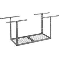
GALS24M1KG - Raised storage shelf Gladiator - Free user manual and instructions
Find the device manual for free GALS24M1KG Gladiator in PDF.


| Product Type | Overhead Storage Rack |
| Brand | Gladiator |
| Model | GALS24M1KG |
| Dimensions (W x D x H) | 61 x 122 x 58.4 cm (24 x 48 x 23 in) (height adjustable up to 96 cm) |
| Maximum Load Capacity | 159 kg (350 lb) |
| Main Material | Steel |
| Color | Granite Gray (KG) |
| Installation Type | Ceiling mount on wood joists or beams |
| Minimum Recommended Clearance Height | 203 cm (80 in) from floor |
| Ceiling Bracket Spacing | Maximum 61 cm (24 in) between brackets |
| Required Tools | Electric drill, 4.8 mm (3/16 in) drill bit, 12.7 mm (1/2 in) socket wrench, 6 mm hex key, stud finder, tape measure, stepladder, pencil, masking tape |
| Included Hardware | M8 cap screws, 5/16 x 3 in lag screws, M8 rectangular nuts, EZ Connect positioning rods, shims (depending on model) |
| Recommended Number of People for Assembly | At least 2 people |
| Maintenance | Clean with mild detergent and warm water; check tightness annually |
| Warranty | Consult website or customer service (US: 1-866-342-4089, Canada: 1-800-807-6777) |
| Reparability | Replacement parts available through manufacturer |
Frequently Asked Questions - GALS24M1KG Gladiator
User questions about GALS24M1KG Gladiator
0 question about this device. Answer the ones you know or ask your own.
Ask a new question about this device
Download the instructions for your Raised storage shelf in PDF format for free! Find your manual GALS24M1KG - Gladiator and take your electronic device back in hand. On this page are published all the documents necessary for the use of your device. GALS24M1KG by Gladiator.
USER MANUAL GALS24M1KG Gladiator
PARTS 2 FT X 4 FT....4
PARTS 2 FT X 8 FT....5
PARTS 4 FT X 4 FT....6
ASSEMBLY INSTRUCTIONS......7
Unpack the Overhead GearLoft™
Storage Rack....7
Tools and Parts 7
Overhead GearLoft™ Storage Rack
Use Requirements ....7
Assembling the Rack 8
Installing the Overhead GearLoft™
Storage Rack....11
Storage Rack Care....11
Registering Your Product......11
WARRANTY....11
SÉCURITÉ DE L'ÉTAGÈRE DE
RANGEMENT SURELEVÉE
GEARLOFT™ 12
DIMENSIONS ......13
PIÈCES 2 PI X 4 PI....14
PIÈCES 2 PI X 8 PI....15
PIÈCES 4 PI X 4 PI....16
INSTRUCTIONS D'ASSEMBLAGE...17
Your safety and the safety of others are very important.
We have provided many important safety messages in this manual and on your appliance. Always read and obey all safety messages.

This is the safety alert symbol.
This symbol alerts you to potential hazards that can kill or hurt you and others.
All safety messages will follow the safety alert symbol and either the word "DANGER" or "WARNING."
These words mean:
DANGER
You can be killed or seriously injured if you don't immediately follow instructions.
WARNING
You can be killed or seriously injured if you don't follow instructions.
All safety messages will tell you what the potential hazard is, tell you how to reduce the chance of injury, and tell you what can happen if the instructions are not followed.
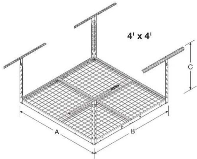
DIMENSIONS
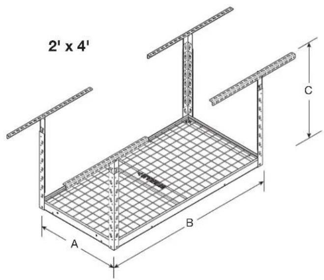
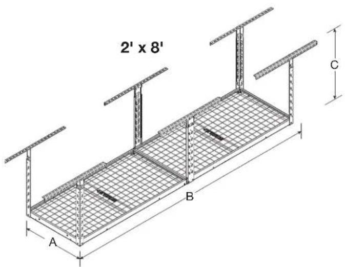
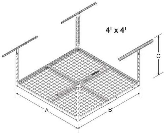
| MODEL | GALS24M1KG GALS24M1KW | GALS28M2KG GALS28M2KW | GALS44M2KG GALS44M2KW |
| A 24" (61 cm) 24" (61 cm) 48" (122 cm) | |||
| B 48" (122 cm) 96" (244 cm) 48" (122 cm) | |||
| C 23" (58.4 cm) min. and 37.8" (96 cm) max. | 23" (58.4 cm) min. and 37.8" (96 cm) max. | 23" (58.4 cm) min. and 37.8" (96 cm) max. | |
PARTS - 2 FT X 4 FT
GALS24M1KG
GALS24M1KW
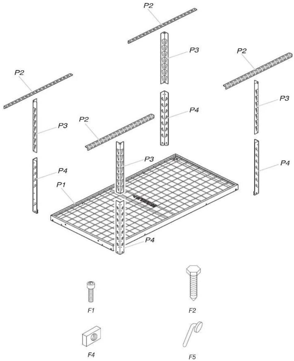
| Label Description Quantity | ||
| P1 2' x 4' rack section 1 | ||
| P2 Ceiling bracket 4 | ||
| P3 Vertical corner support - upper 4 | ||
| P4 Vertical corner support - lower 4 | ||
| F1 M8 - | 1.25 x 12 socket-head cap screw 12 | |
| F2 5/16' x 3" lag bolt 8 | ||
| F4 | M8 - 1.25 rectangular nut | 4 |
| F5 | EZ Connect locking pin | 4 |
PARTS - 2 FT X 8 FT
GALS28M2KG
GALS28M2KW
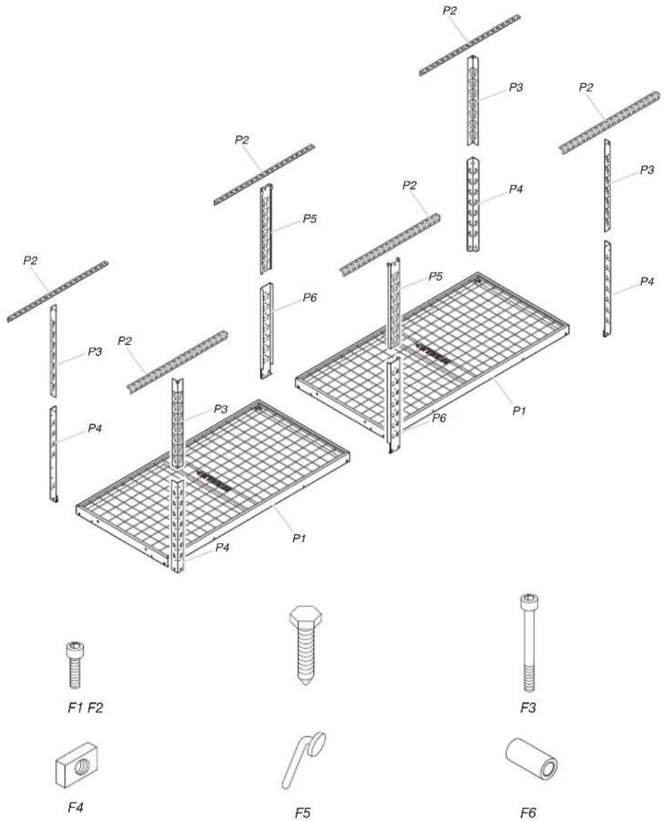
| Label Description Quantity | ||
| P1 2' x 4' rack section 2 | ||
| P2 Ceiling bracket 6 | ||
| P3 Vertical corner support - upper 4 | ||
| P4 Vertical corner support - lower 4 | ||
| P5 Vertical center support - upper 2 | ||
| P6 Vertical center support - lower 2 | ||
| F1 M8 - 1.25 x 12 socket-head cap screw 22 | ||
| F2 | 5/16" x 3" lag bolt | 12 |
| F3 M8 - 1.25 x 75 socket-head cap screw 2 | ||
| F4 | M8 - 1.25 rectangular nut | 10 |
| F5 | EZ Connect locking pin | 6 |
| F6 | Spacer | 4 |
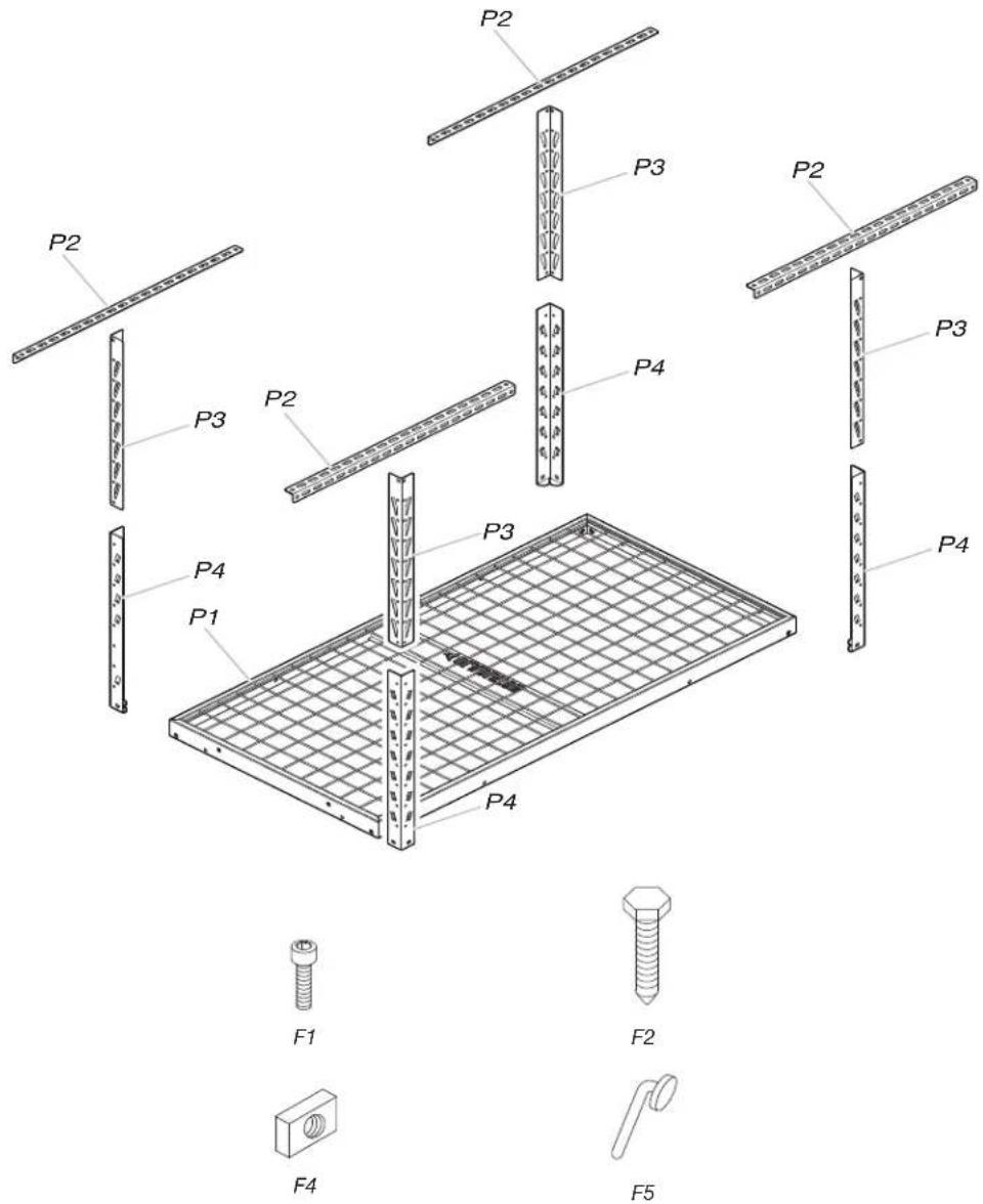
PARTS - 4 FT X 4 FT
GALS44M2KG
GALS44M2KW
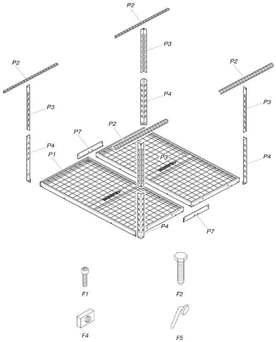
| Label Description Quantity | ||
| P1 2' x 4' rack section 2 | ||
| P2 Ceiling bracket 4 | ||
| P3 Vertical corner support - upper 4 | ||
| P4 Vertical corner support - lower 4 | ||
| P7 Rack connection bracket 2 | ||
| F1 M8 - 1.25 x 12 socket-head cap screw 22 | ||
| F2 5/16" x 3" lag bolt 8 | ||
| F4 | M8 - 1.25 rectangular nut | 6 |
| F5 | EZ Connect locking pin | 4 |
ASSEMBLY INSTRUCTIONS
Unpack the Overhead GearLoft™ Storage Rack
- Unpack the rack sections, support sections, ceiling brackets and all hardware. Verify contents. See "Parts."
- Dispose of all packaging materials properly.
Tools and Parts
■Install Overhead GearLoft™ Storage Rack according to manufacturer's instructions and any local codes.
■Only use provided fasteners. Do not use an alternate form of mounting. Do not alter or modify any components included with this product.
■Gather the required tools and parts before starting assembly.
■Read entire manual before starting assembly.
WARNING
Excessive Weight Hazard
Use two or more people to move storage rack.
Failure to do so can result in back or other injury.
Tools Needed
■Electric drill
■Drill bit (3/16") - included
■1/2" socket wrench and/or 1/2" open end wrench
■6 mm hex wrench - included
■Stud finder (If ceiling has drywall covering joists/rafters)
■Tape measure
■Step stool or step ladder
■Pencil / Marker
■Masking tape
Overhead GearLoft™ Storage Rack Use Requirements
- Intended for garage use, installed into a wood framed/traditional wood structure type dwelling.
- To be used for storing lightweight items overhead and out of the way.
- Recommended to be positioned 80" minimum above floor (standard door opening height).
- Check for clearance of all doors, vehicles, or any items to be positioned under the storage rack.
- The maximum weight of all items combined on the rack not to exceed:
2 ft x 4 ft - 350 lbs.
2 ft x 8 ft - 500 lbs.
4 ft x 4 ft - 500 lbs.
Assembling the Rack
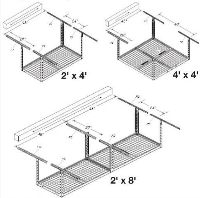
1. Determine the ceiling bracket locations
Parallel layout
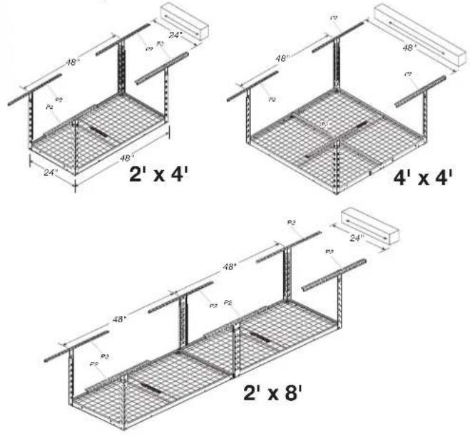
Perpendicular layout
2. Attach the ceiling brackets
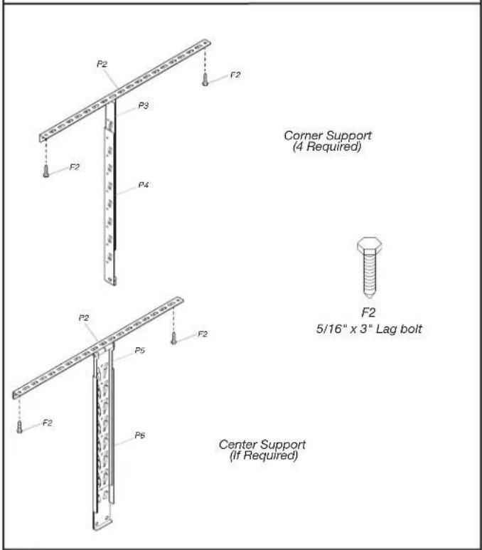
Using the provided drill bit (3/16"), drill all pilot holes in the center of the joists/rafters. Two lag bolts must be used on each bracket, one on each side of the vertical support. Mount the ceiling brackets (P2) using 5/16" x 3" lag bolts (F2) (8 or 12).
The storage rack ceiling brackets can be positioned parallel or perpendicular to the wood ceiling joists/rafters. Determine the application required for your desired installation. If drywall covers the joists, use a stud finder to determine the joist/rafter locations and mark with masking tape. For applications requiring installation of the brackets perpendicular to the joists/rafters, the maximum distance between them is 24". The brackets included allow for a 24" maximum span. See figure for typical ceiling layouts. Mark the location of the ceiling brackets on the joists/rafters or drywall, making sure the vertical supports can be positioned between the lag bolts used to attach the brackets. Position the center of the brackets on a 24"/48" grid as required.
- Connect the racks (4' x 4', 2' x 8')
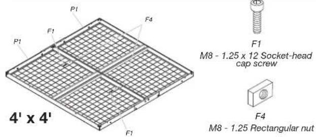
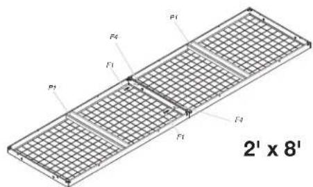
Lay two rack sections upside down on the floor. Assemble the rack sections (P1) together using M8 - 1.25 x 12 socket-head cap screws (F1) (2) and M8 - 1.25 Rectangular nuts (F4) (2).
- Attach lower corner supports
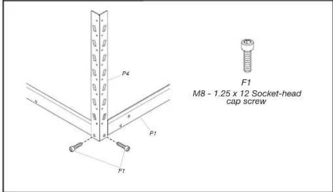
Attach the four lower corner supports (P4) to the rack corners using M8 - 1.25 x 12 socket-head cap screws (F1) (8).
- Attach the rack brackets (4' x 4')
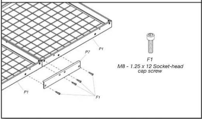
Attach the rack connection brackets (P7) to both sides of the two bolted-together rack sections using M8 - 1.25 x 12 socket-head cap screws (F1) (8).
- Attach lower center supports (2' x 8')
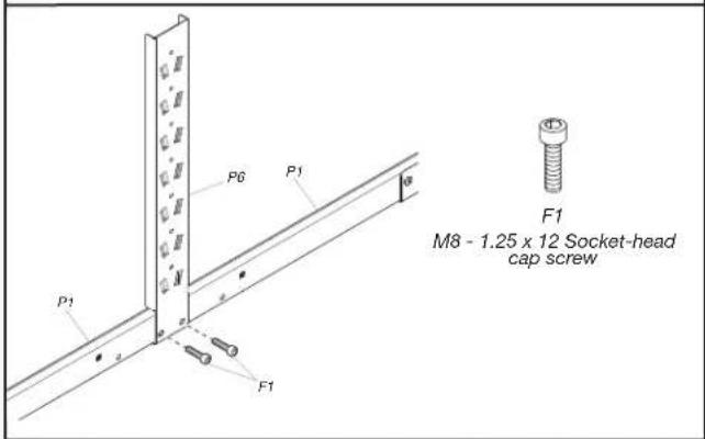
Attach the two lower center supports (P6) to the rack assembly using M8 - 1.25 x 12 socket-head cap screws (F1) (4).
- Attach upper corner supports
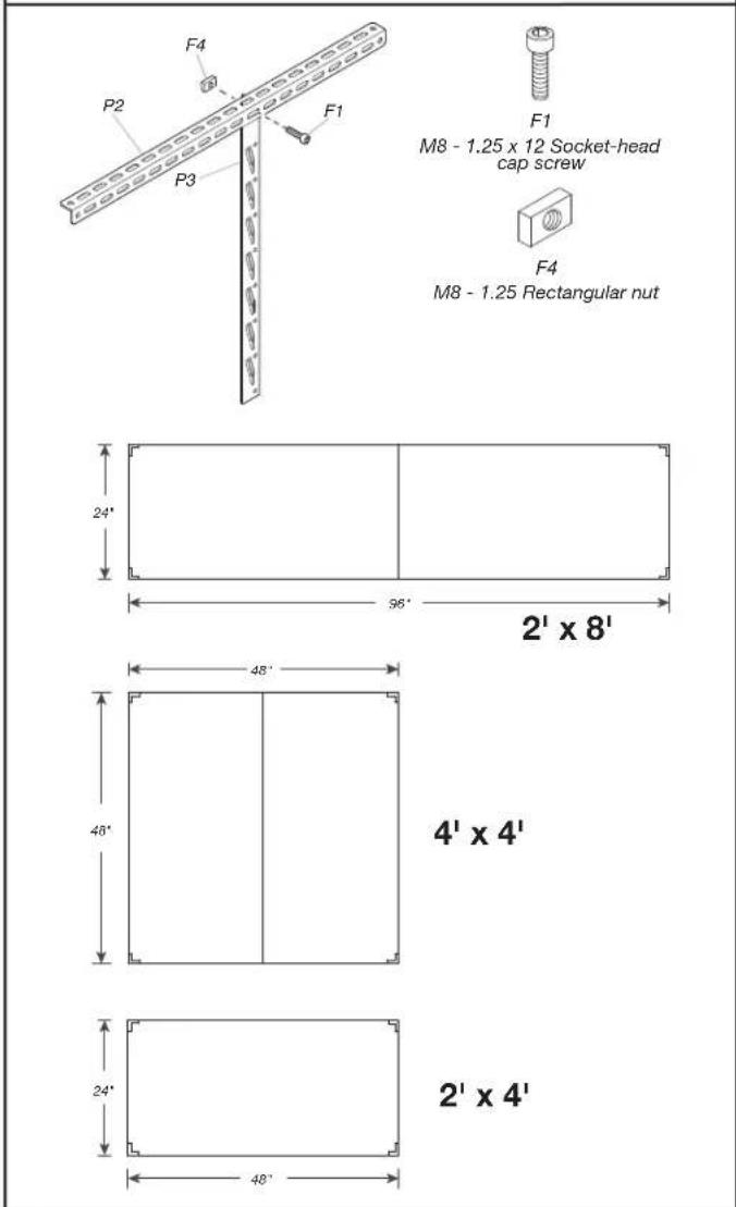
Attach the upper corner support (P3) to the ceiling brackets using M8 - 1.25 x 12 (F1) (4) and M8 - 1.25 rectangular nuts (F4) (4). Make sure they are positioned on the 24"/48" layout as required.
- Attach upper center supports (2' x 8')
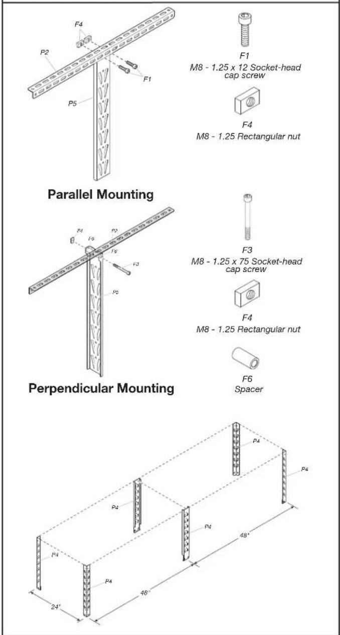
Attach the upper center supports (P5) to the ceiling brackets using one of the methods detailed above, depending on ceiling bracket mounting approach.
Parallel Mounting
Attach supports using M8 - 1.25 x 12 socket-head cap screws (F1) (2) and M8 - 1.25 rectangular nuts (F4) (2) on each upper center support.
Perpendicular Mounting
Attach supports using M8 - 1.25 x 75 socket-head cap screws (F3), M8 - 1.25 rectangular nuts (F4) and spacer (F6) (2) on each upper center support. Verify that all of the upper supports are properly spaced. They should be on a 24"/48" pattern as shown in the figure.
Installing the Overhead GearLoft™ Storage Rack
WARNING
Excessive Weight Hazard
Use two or more people to move storage rack.
Failure to do so can result in back or other injury.
- Attach the EZ Connect supports
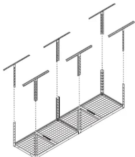
Using two or more people, the rack system can be easily lifted and positioned overhead. The EZ Connect feature allows for positioning 23" to 37.8" from the ceiling. Lift the rack into place and connect the lower supports to the upper supports. Make sure the rack supports are facing the same way and the rack is level.
- Complete the assembly
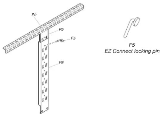
Make sure all bolts and screws are tight. Once the rack is in the desired location below the ceiling, place an EZ Connect locking pin (F5) in a hole on each of the corner and center supports to lock/retain them together. The pins go through both upper and lower supports.
NOTE: The rack system can be repositioned up or down by removing all locking pins and relocating the EZ Connect position on the supports. Use two or more people to relocate the rack and replace the EZ Connect locking pins (F5).
Storage Rack Care
■ Wash storage rack with a mild liquid detergent and warm water using a soft, clean cloth.
■Check fastener tightness annually.
Registering Your Product
There are many benefits of registering your product. Find out more and register your product online at www.gladiatorgarageworks.com. In the USA, call 1-866-342-4089. Consumers in Canada can call 1-800-807-6777.
WARRANTY
For warranty information:
In the U.S.A. call 1-866-342-4089 or visit our website at
www.gladiatorgarageworks.com
In Canada call 1-800-807-6777 or visit our website at
www.gladiatorgarageworks.ca
SÉCURITÉ DE L'ÉTAGÈRE DE RANGEMENT SURÉLEVÉE GEARLOFT™
www.gladiatorgarageworks.com
www.gladiatorgarageworks.ca
SEGURIDAD DE LA ESTANTERÍA DE ALMACENAMIENTO GEARLOFT™ EN ALTURA
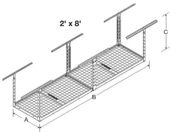
| MODELO | GALS24M1KG GALS24M1KW | GALS28M2KG GALS28M2KW | GALS44M2KG GALS44M2KW |
| A 24" (61 cm) 24" (61 cm) 48" (122 cm) | |||
| B 48" (122 cm) 96" (244 cm) 48" (122 cm) | |||
| C 23" (58,4 cm) mín. y 37,8" (96 cm) máx. | 23" (58,4 cm) mín. y 37,8" (96 cm) máx. | 23" (58,4 cm) mín. y 37,8" (96 cm) máx. | |
PIEZAS - 2 PIES X 4 PIES
GALS24M1KG
GALS24M1KW
www.gladiatorgarageworks.com
www.gladiatorgarageworks.ca
® / TM ©2024 Gladiator. All rights reserved. Used under license in Canada.


- SÉCURITÉ DE L'ÉTAGÈRE DE
- YOUR SAFETY AND THE SAFETY OF OTHERS ARE VERY IMPORTANT
- DANGER
- WARNING
- DIMENSIONS
- ASSEMBLY INSTRUCTIONS
- UNPACK THE OVERHEAD GEARLOFT™ STORAGE RACK
- TOOLS AND PARTS
- EXCESSIVE WEIGHT HAZARD
- TOOLS NEEDED
- OVERHEAD GEARLOFT™ STORAGE RACK USE REQUIREMENTS
- ASSEMBLING THE RACK
- DETERMINE THE CEILING BRACKET LOCATIONS
- ATTACH THE CEILING BRACKETS
- PARALLEL MOUNTING
- PERPENDICULAR MOUNTING
- INSTALLING THE OVERHEAD GEARLOFT™ STORAGE RACK
- STORAGE RACK CARE
- REGISTERING YOUR PRODUCT
- WARRANTY
- SÉCURITÉ DE L'ÉTAGÈRE DE RANGEMENT SURÉLEVÉE GEARLOFT™
- SEGURIDAD DE LA ESTANTERÍA DE ALMACENAMIENTO GEARLOFT™ EN ALTURA
Brand : Gladiator
Model : GALS24M1KG
Category : Raised storage shelf