
DBN901 - Stapler MAKITA - Free user manual and instructions
Find the device manual for free DBN901 MAKITA in PDF.

User questions about DBN901 MAKITA
0 question about this device. Answer the ones you know or ask your own.
Ask a new question about this device
Download the instructions for your Stapler in PDF format for free! Find your manual DBN901 - MAKITA and take your electronic device back in hand. On this page are published all the documents necessary for the use of your device. DBN901 by MAKITA.
USER MANUAL DBN901 MAKITA
natural_image
Technical line drawing of two mechanical assembly components (no text or symbols)
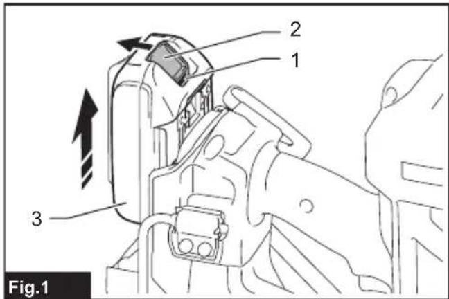
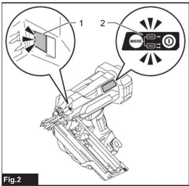
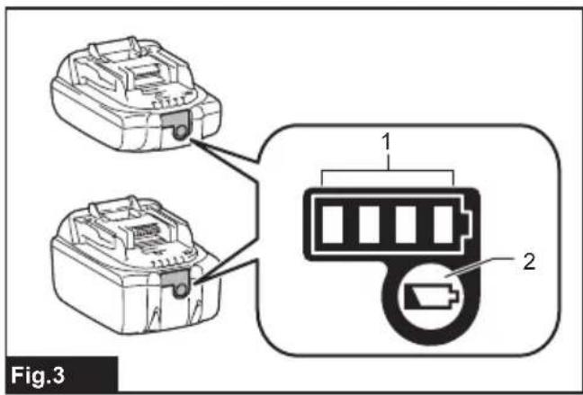
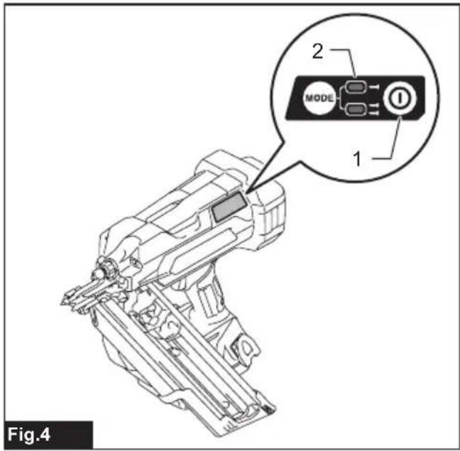
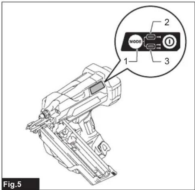
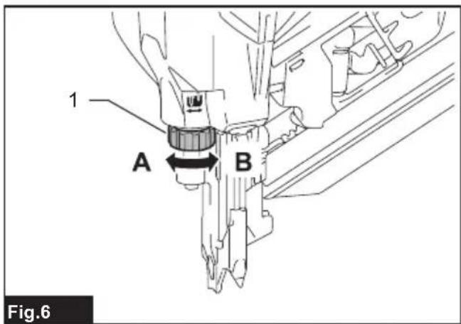
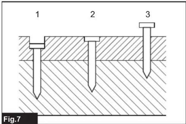
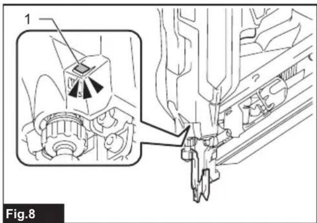
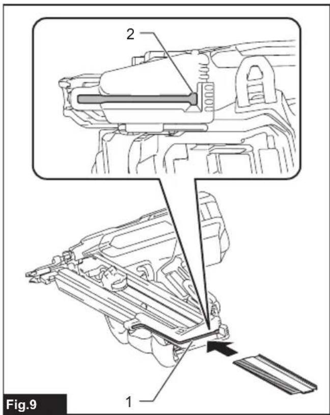
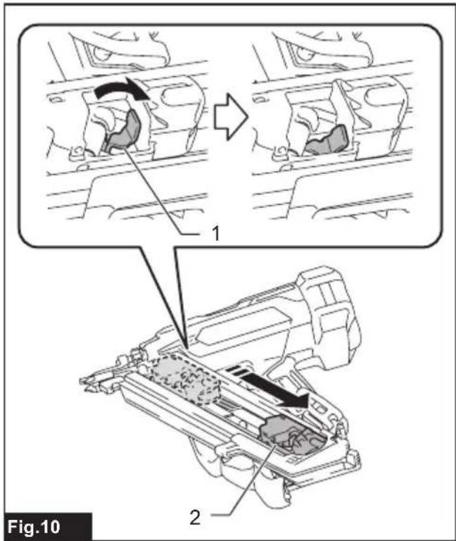

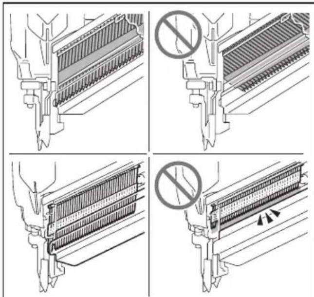
Fig.12
natural_image
Technical line drawing of a mechanical assembly with labeled component (no text or symbols present)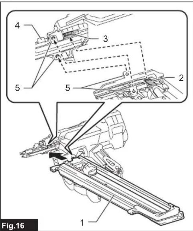
natural_image
Technical line drawing of a mechanical assembly with a circular prohibition symbol (no text or labels)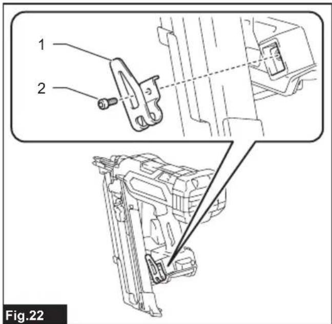
natural_image
Mechanical assembly diagram showing a valve or connector with directional arrows indicating movement (no text or symbols present)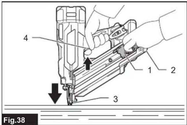
SPECIFICATIONS
| Model: DBN900 DBN901 | ||
| Figure of nail head Clipped Round | ||
| Nail length 50 mm - 90 mm | ||
| Shank diameter ø2.9 mm - ø3.3 mm ø2.9 mm - ø3.8 mm | ||
| Magazine capacity 51 - 58 nails (1 strip + 11 - 18 nails) | 36 - 41 nails (1 strip + 11 - 16 nails) | |
| Nail collation angle 30° - 34° 20° - 22° | ||
| Dimensions (L x W x H) ^1 | 326 mm x 186 mm x 358 mm | 389 mm x 189 mm x 358 mm |
| Rated voltage D.C. 18 V | ||
| Net weight 4.9 - 5.4 kg | 5.0 - 5.4 kg | |
^*1 without hooks
- Due to our continuing program of research and development, the specifications herein are subject to change without notice.
• Specifications may differ from country to country.
- The weight may differ depending on the attachment(s), including the battery cartridge. The lightest and heaviest combination are shown in the table.
Applicable battery cartridge and charger
| Battery cartridge | BL1820B / BL1830B / BL1840B / BL1850B / BL1860B |
| Charger | DC18RC / DC18RD / DC18RE / DC18SD / DC18SE / DC18SF / DC18SH / DC18WC |
• Some of the battery cartridges and chargers listed above may not be available depending on your region of residence.

WARNING: Only use the battery cartridges and chargers listed above. Use of any other battery cartridges and chargers may cause injury and/or fire.
Symbols
The followings show the symbols which may be used for the equipment. Be sure that you understand their meaning before use.


Ni-MH Li-ion
Only for EU countries
Due to the presence of hazardous components in the equipment, waste electrical and electronic equipment, accumulators and batteries may have a negative impact on the environment and human health. Do not dispose of electrical and electronic appliances or batteries with household waste!
In accordance with the European Directive on waste electrical and electronic equipment and on accumulators and batteries and waste accumulators and batteries, as well as their adaptation to national law, waste electrical equipment, batteries and accumulators should be stored separately and delivered to a separate collection point for municipal waste, operating in accordance with the regulations on environmental protection.
This is indicated by the symbol of the crossed-out wheeled bin placed on the equipment.
Intended use
The tool is intended for the preliminary interior work such as fixing floor joists or common rafters and framing work in 2" x 4" housing.
Noise
The typical A-weighted noise level determined according to EN60745-2-16:
Model DBN900
Sound pressure level (L _pA ) : 90 dB (A)
Sound power level ( L_WA ): 101 dB (A)
Uncertainty (K) : 3 dB (A)
Model DBN901
Sound pressure level (L _pA ) : 92 dB(A)
Sound power level ( L_WA ): 103 dB (A)
Uncertainty (K) : 3 dB(A)
NOTE: The declared noise emission value(s) has been measured in accordance with a standard test method and may be used for comparing one tool with another.
NOTE: The declared noise emission value(s) may also be used in a preliminary assessment of exposure.

WARNING: Wear ear protection.
⚠ WARNING: The noise emission during actual use of the power tool can differ from the declared value(s) depending on the ways in which the tool is used especially what kind of workpiece is processed.
⚠ WARNING: Be sure to identify safety measures to protect the operator that are based on an estimation of exposure in the actual conditions of use (taking account of all parts of the operating cycle such as the times when the tool is switched off and when it is running idle in addition to the trigger time).
Vibration
The vibration total value determined according to EN60745-2-16:
Model DBN900
Vibration emission (ah): 3.4 m/s²
Uncertainty (K) : 1.5 m/s ^2
Model DBN901
Vibration emission (a_h):3.5m / s^2
Uncertainty (K) : 1.5 m/s ^2
NOTE: The declared vibration total value(s) has been measured in accordance with a standard test method and may be used for comparing one tool with another.
NOTE: The declared vibration total value(s) may also be used in a preliminary assessment of exposure.

WARNING: The vibration emission during dual use of the power tool can differ from the declared value(s) depending on the ways in which the tool is used especially what kind of workpiece processed.

WARNING: Be sure to identify safety measures to protect the operator that are based on animation of exposure in the actual conditions of the (taking account of all parts of the operating cycle such as the times when the tool is switched and when it is running idle in addition to the bigger time).
Declarations of Conformity
For European countries only
The Declarations of conformity are included in Annex A to this instruction manual.
SAFETY WARNINGS
General power tool safety warnings

WARNING Read all safety warnings, instruct- ns, illustrations and specifications provided with s power tool. Failure to follow all instructions listed ow may result in electric shock, fire and/or serious jury.
Save all warnings and instructions for future reference.
The term "power tool" in the warnings refers to your mains-operated (corded) power tool or battery-operated (cordless) power tool.
Cordless nailer safety warnings
- Always assume that the tool contains fasteners. Careless handling of the nailer can result in unexpected firing of fasteners and personal injury.
- Do not point the tool towards yourself or anyone nearby. Unexpected triggering will discharge the fastener causing an injury.
- Do not actuate the tool unless the tool is placed firmly against the workpiece. If the tool is not in contact with the workpiece, the fastener may be deflected away from your target.
- Disconnect the tool from the power source when the fastener jams in the tool. While removing a jammed fastener, the nailer may be accidentally activated if it is plugged in.
- Use caution while removing a jammed fastener. The mechanism may be under compression and the fastener may be forcefully discharged while attempting to free a jammed condition.
- Do not use this nailer for fastening electrical cables. It is not designed for electric cable installation and may damage the insulation of electric cables thereby causing electric shock or fire hazards.
- Always wear safety glasses to protect your eyes from dust or fastener injury.
- Keep hands and feet away from the ejection port area.
- Always remove the battery cartridge before loading the fasteners, adjustment, inspection, maintenance or after operation is over.
- Make sure no one is nearby before operation. Never attempt to drive fasteners from both the inside and outside of wall at the same time. Fasteners may rip through and/or fly off, presenting a grave danger.
- Watch your footing and maintain your balance with the tool. Make sure there is no one below
when working in high locations.
-
Never use fastener driving tools marked with the symbol "Do not use on scaffoldings, ladders" for specific application for example:
-
when changing one driving location to another involves the use of scaffoldings, stairs, ladders, or ladder alike constructions, e.g. roof laths;
• closing boxes or crates; -
fitting transportation safety systems e.g. on vehicles and wagons.
-
Check walls, ceilings, floors, roofing and the like carefully to avoid possible electrical shock, gas leakage, explosions, etc. caused by stapling into live wires, conduits or gas pipes.
- Use only fasteners specified in this manual. The use of any other fasteners may cause malfunction of the tool.
- Do not tamper with the tool or attempt to use it for other than driving fasteners.
- Do not operate the tool without fasteners. It shortens the service life of the tool.
- Stop driving operations immediately if you notice something wrong or out of the ordinary with the tool.
- Never fasten into any materials which may allow the fastener to puncture and fly through as a projectile.
- Never actuate the switch trigger and contact element at the same time until you are prepared to fasten workpieces. Allow the workpiece to depress the contact element. Never defeat its purpose by securing the contact element back or by depressing it by hand.
- Never tamper with the contact element. Check the contact element frequently for proper operations.
- Always remove fasteners from the tool when not in use.
- Avoid placing magnets or similar magnetic device too close to the tool. It may affect the magnetic sensor in the tool.
SAVE THESE INSTRUCTIONS.
WARNING: DO NOT let comfort or familiarity with product (gained from repeated use) replace strict adherence to safety rules for the subject product. MISUSE or failure to follow the safety rules stated in this instruction manual may cause serious personal injury.
Important safety instructions for battery cartridge
- Before using battery cartridge, read all instructions and cautionary markings on (1) battery charger, (2) battery, and (3) product using battery.
- Do not disassemble or tamper with the battery cartridge. It may result in a fire, excessive heat, or explosion.
- If operating time has become excessively shorter, stop operating immediately. It may
result in a risk of overheating, possible burns and even an explosion.
- If electrolyte gets into your eyes, rinse them out with clear water and seek medical attention right away. It may result in loss of your eyesight.
- Do not short the battery cartridge:
(1) Do not touch the terminals with any conductive material.
(2) Avoid storing battery cartridge in a container with other metal objects such as nails, coins, etc.
(3) Do not expose battery cartridge to water or rain.
A battery short can cause a large current flow, overheating, possible burns and even a breakdown.
- Do not store and use the tool and battery cartridge in locations where the temperature may reach or exceed 50 °C (122 °F).
- Do not incinerate the battery cartridge even if it is severely damaged or is completely worn out. The battery cartridge can explode in a fire.
- Do not nail, cut, crush, throw, drop the battery cartridge, or hit against a hard object to the battery cartridge. Such conduct may result in a fire, excessive heat, or explosion.
- Do not use a damaged battery.
- The contained lithium-ion batteries are subject to the Dangerous Goods Legislation requirements.
For commercial transports e.g. by third parties, forwarding agents, special requirement on packaging and labeling must be observed.
For preparation of the item being shipped, consulting an expert for hazardous material is required.
Please also observe possibly more detailed national regulations.
Tape or mask off open contacts and pack up the battery in such a manner that it cannot move around in the packaging.
- When disposing the battery cartridge, remove it from the tool and dispose of it in a safe place. Follow your local regulations relating to disposal of battery.
- Use the batteries only with the products specified by Makita. Installing the batteries to non-compliant products may result in a fire, excessive heat, explosion, or leak of electrolyte.
- If the tool is not used for a long period of time, the battery must be removed from the tool.
- During and after use, the battery cartridge may take on heat which can cause burns or low temperature burns. Pay attention to the handling of hot battery cartridges.
- Do not touch the terminal of the tool immediately after use as it may get hot enough to cause burns.
- Do not allow chips, dust, or soil stuck into the terminals, holes, and grooves of the battery cartridge. It may cause heating, catching fire, burst and malfunction of the tool or battery cartridge, resulting in burns or personal injury.
- Unless the tool supports the use near
high-voltage electrical power lines, do not use the battery cartridge near high-voltage electrical power lines. It may result in a malfunction or breakdown of the tool or battery cartridge.
18. Keep the battery away from children.
SAVE THESE INSTRUCTIONS.
CAUTION: Only use genuine Makita batteries.
Use of non-genuine Makita batteries, or batteries that have been altered, may result in the battery bursting causing fires, personal injury and damage. It will also void the Makita warranty for the Makita tool and charger.
Tips for maintaining maximum battery life
- Charge the battery cartridge before completely discharged. Always stop tool operation and charge the battery cartridge when you notice less tool power.
- Never recharge a fully charged battery cartridge. Overcharging shortens the battery service life.
- Charge the battery cartridge with room temperature at 10 °C - 40 °C ( 50 °F - 104 °F ). Let a hot battery cartridge cool down before charging it.
- When not using the battery cartridge, remove it from the tool or the charger.
- Charge the battery cartridge if you do not use it for a long period (more than six months).
FUNCTIONAL DESCRIPTION
⚠️CAUTION: Always be sure that the tool is switched off and the battery cartridge is removed before adjusting or checking function on the tool.
Installing or removing battery cartridge
⚠️CAUTION: Always switch off the tool before installing or removing of the battery cartridge.
⚠️CAUTION: Hold the tool and the battery cartridge firmly when installing or removing battery cartridge. Failure to hold the tool and the battery cartridge firmly may cause them to slip off your hands and result in damage to the tool and battery cartridge and a personal injury.
To install the battery cartridge, align the tongue on the battery cartridge with the groove in the housing and slip it into place. Insert it all the way until it locks in place with a little click. If you can see the red indicator as shown in the figure, it is not locked completely.
To remove the battery cartridge, slide it from the tool while sliding the button on the front of the cartridge.
▶ Fig.1: 1. Red indicator 2. Button 3. Battery cartridge
CAUTION: Always install the battery cartridge fully until the red indicator cannot be seen. If not, it may accidentally fall out of the tool, causing injury to you or someone around you.
⚠️ CAUTION: Do not install the battery cartridge forcibly. If the cartridge does not slide in easily, it is not being inserted correctly.
Tool / battery protection system
The tool is equipped with a tool/battery protection system. This system automatically cuts off power to the motor to extend tool and battery life. The tool will automatically stop during operation if the tool or battery is placed under one of the following conditions:
▶ Fig.2: 1. Lamp 2. Power/mode indicator
* The switch design varies depending on your region of residence.
Protection status indication
| Lamp Power/mode indicator | Status | |||
 |  |  |  | |
| On Blinking On Blinking | ||||
 |  | Overheat | ||
 |  | Over discharge | ||
Overheat protection
When the tool/battery is overheated, the tool stops automatically providing status indication. In this situation, let the tool/battery cool before turning the tool on again.
Overdischarge protection
When the battery capacity becomes low, the tool stops automatically. In this case, remove the battery from the tool and charge the battery.
Protections against other causes
Protection system is also designed for other causes that could damage the tool and allows the tool to stop automatically. Take all the following steps to clear the causes, when the tool has been brought to a temporary halt or stop in operation.
- Turn the tool off, and then turn it on again to restart.
- Charge the battery(ies) or replace it/them with recharged battery(ies).
- Let the machine and battery(ies) cool down.
If no improvement can be found by restoring protection system, then contact your local Makita Service Center.
Indicating the remaining battery capacity
Only for battery cartridges with the indicator
Press the check button on the battery cartridge to indicate the remaining battery capacity. The indicator lamps light up for a few seconds.
▶ Fig.3: 1. Indicator lamps 2. Check button
| Indicator lamps Remaining | capacity | ||
| Lighted Off |  Blinking Blinking | ||
 | 75% to 100% | ||
 | 50% to 75% | ||
 | 25% to 50% | ||
 | 0% to 25% | ||
 | Charge the battery. | ||
 | The battery may have malfunctioned. | ||
NOTE: Depending on the conditions of use and the ambient temperature, the indication may differ slightly from the actual capacity.
NOTE: The first (far left) indicator lamp will blink when the battery protection system works.
Power switch action
⚠️CAUTION: Before installing the battery cartridge into the tool, always check to see that the switch trigger actuates properly and returns to the "OFF" position when released.
Press and hold the main power button to turn on the tool. The power indicator lights up.
To turn off the tool, press and hold the main power button until the power indicator goes off.
NOTE: The switch design varies depending on your region of residence.
▶ Fig.4: 1. Main power button 2. Power indicator
NOTE: The tool cannot be turned on while either the switch trigger or the contact element is actuated. Be sure to release the switch trigger and the contact element before turning on the tool.
NOTE: The tool cannot be turned off while driving nails.
NOTE: The main power switch will automatically shut down if the tool is left unattended for an extended duration.
Selecting actuation mode
Country specific
NOTE: Only a single nailing mode is available in some regions or countries. The switch design varies depending on your region of residence.
The tool employs a selective-actuation triggering. Press and shortly hold the actuation mode switch button to select the desired actuation mode.
▶ Fig.5: 1. Actuation mode switch button
-
Sequential actuation mode lamp
-
Contact actuation mode lamp
| Mode switch | Actuation mode | Feature |
 | Full sequential actuation | Drive one nail in one sequential operation. Suitable for driving a nail carefully and accurately and helpful when you require precise fastener placement. |
 | Contact actuation | Either a single nailing or continuous nailing is available. Preferred when you require high productive fastener placement. |
- : Unavailable in some regions and countries.
NOTE: Actuation mode cannot be switched to another while either the switch trigger or the contact element is actuated.
Adjusting the nailing depth
WARNING: Always make sure that your fingers are not placed on the switch trigger or the contact element and the battery cartridge is removed before adjusting the depth of nailing.
Turn the adjuster to adjust the nailing depth. The nailing depth gets deeper as you turn the adjuster to A direction, shallower to B direction in the figure. The range of the nailing depth adjustment is 8.5 mm.
▶ Fig.6: 1. Adjuster
NOTICE: Do not turn the adjuster too much, or the adjuster may get stuck.
Adjust the nailing depth as necessary.
▶ Fig.7: 1. Too deep 2. Flush 3. Too shallow
Lighting up the lamp
⚠️ CAUTION: Do not look in the light or see the source of light directly.
Pull the switch trigger or actuate the contact element to light up the lamp. The lamp keeps on lighting while pulling the switch trigger or actuating the contact element. The lamp goes out approximately 10 seconds after releasing the switch trigger and the contact element.
▶ Fig.8: 1. Lamp
NOTE: Use a dry cloth to wipe the dirt off the lens of the lamp. Be careful not to scratch the lens of the lamp, or it may lower the illumination.
NOTE: The tool may not drive nails after the battery becomes low on power even while the lamp remains lit. In this case, charge the battery cartridge.
ASSEMBLY
⚠️CAUTION: Always make sure that your fingers are not placed on the switch trigger or the contact element and the battery cartridge is removed before carrying out any work on the nailer.
Loading or unloading the nails
⚠️CAUTION: Always make sure that the battery cartridge is removed before loading the nails. Unintentional firing may cause personal injuries and property damage.
⚠️CAUTION: Be careful not to get your fingers caught in the magazine. The nail pusher tends to spring back to its original position unless you take the counteraction.
NOTICE: Gently slide the nail pusher along the magazine. A forceful contact between the nail pusher and nail strip may damage the nails.
- Remove the battery cartridge.
- Insert a nail strip into the slit of the magazine.
Make sure to align the outlines of the nail heads with that of the slit.
▶ Fig.9: 1. Slit 2. Nail head outline - Pinch the pusher lever to raise the pusher plate up above the nail strip loaded. Then pull the nail pusher towards the slit.
▶ Fig.10: 1. Pusher lever 2. Nail pusher - Set the pusher lever free and slide the nail pusher back by releasing the spring tension safely.
▶ Fig.11: 1. Pusher lever 2. Nail pusher
NOTICE: Make sure that the nail strip is properly aligned in the magazine and secured with the pusher plate.
If not, try reloading.
NOTICE: Do not use deformed nails and nail strips. Use nails specified in this manual. Using nails other than those specified may cause nail jamming and malfunction.
▶ Fig.12
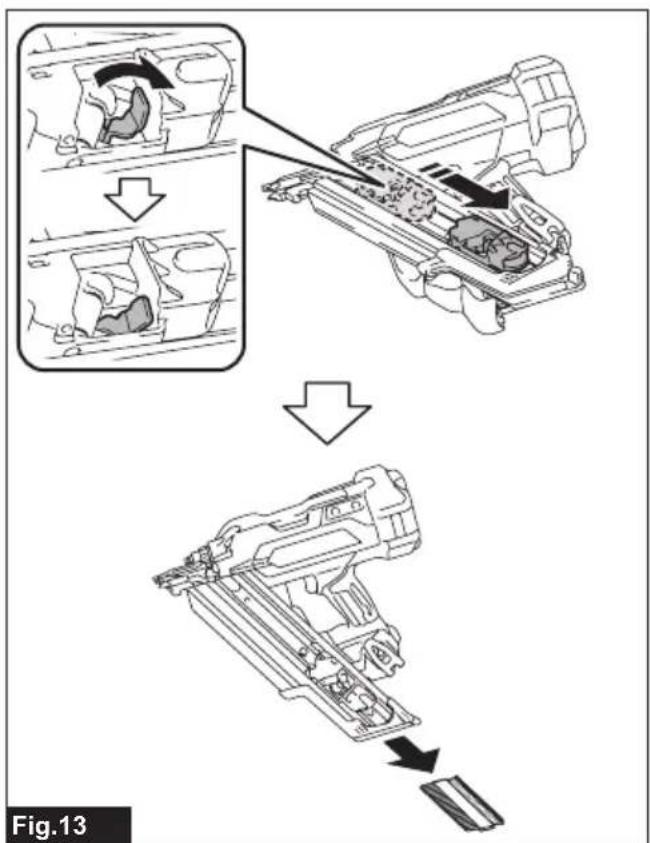
To remove nails, follow the installation procedures in reverse.
▶ Fig.13
Installing extended capacity magazine
Optional accessory
CAUTION: Always make sure to unload all the nails left in the magazine and remove the battery cartridge from the tool before installing an extended capacity magazine.
Use a large-capacity magazine attachment so the tool carries more nails.
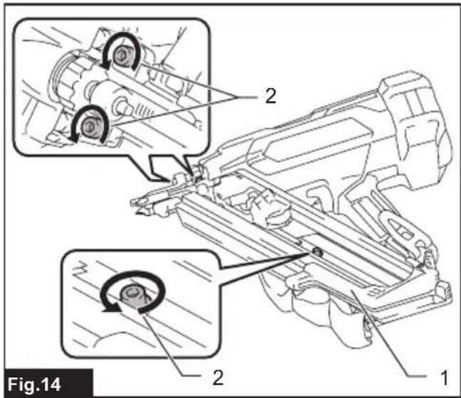
- Loosen and remove the bolts that secure the magazine using the hex wrench.
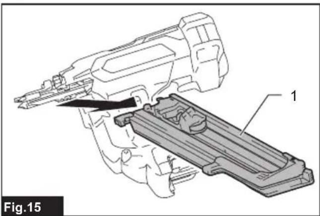
▶ Fig.14: 1. Magazine 2. Bolts - Lift the free end of the standard equipped magazine slightly and pull it straight out.
▶ Fig.15: 1. Standard equipped magazine - Insert the lock plate in the extended capacity magazine into the lock groove in the driver guide at an angle. Align the bolt holes in the magazine with those in the driver guide. Then tighten the bolts a little at a time using the hex wrench.
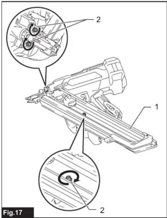
▶ Fig.16: 1. Extended capacity magazine 2. Lock plate 3. Lock groove 4. Driver guide 5. Bolt holes - Tighten the extended capacity magazine on the tool body with the bolt.
- Retighten all the bolts up to secure the extended capacity magazine.
▶ Fig.17: 1. Extended capacity magazine 2. Bolts
Nose adapter
CAUTION: Always make sure that your fingers are not placed on the switch trigger or the contact element, and remove all the nails left in the magazine and the battery cartridge before attaching or detaching the nose adapter.
When firing nails on the material with easily-marred surfaces, attach the nose adapter onto the contact top.
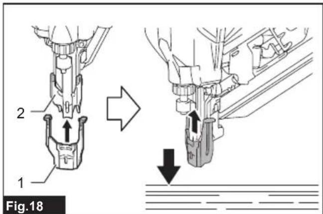
Attaching nose adapter
- Lightly place the nose adapter over the contact top.
- Release the switch trigger.
- Place the contact element flat on the material that can be damaged.
- Push the contact element through until the nose adapter securely fits onto the contact top.
▶ Fig.18: 1. Nose adapter 2. Contact top
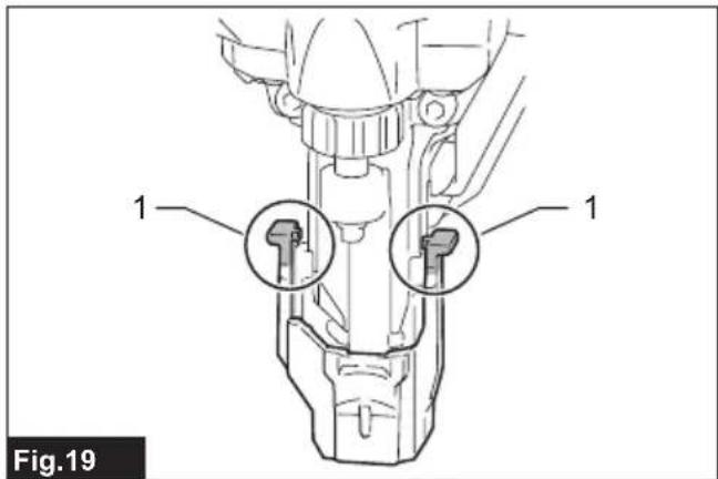
NOTE: Make sure that the hooked arm ends of the nose adapter fully engage the contact top.
▶ Fig.19: 1. Hooked arm ends
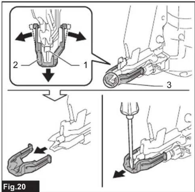
Detaching nose adapter
- Turn the tool upside down.
- Disengage the arms of the nose adapter from the contact top and slide the nose adapter out of the assembly.
NOTE: Use a slotted screwdriver to pry apart pieces if you find it hard to detach the nose adapter.
▶ Fig.20: 1. Contact top 2. Nose adapter 3. Gap
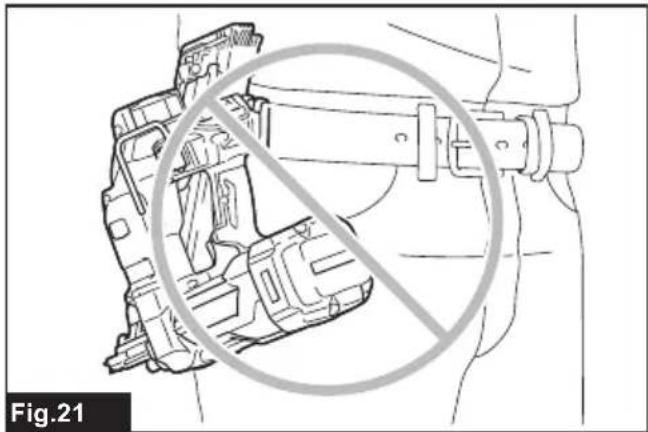
Tool hanging
Two types of tool hooks are available according to your needs. Use either a clip-shaped hook or C-shaped hook to hang the tool on a tool rack, rail or the wall.
⚠️CAUTION: Do not hang the hook from the waist belt. Dropping the nailer, which is caused by the hook accidentally coming out of place, may cause unintentional firing and result in personal injuries.
▶ Fig.21
Clip-shaped hook
Insert the clip-shaped hook into a groove in the tool housing, and then secure it with a hex bolt. To remove the clip-shaped hook, loosen the bolt and then take the hook out.
▶ Fig.22: 1. Clip-shaped hook 2. Hex bolt
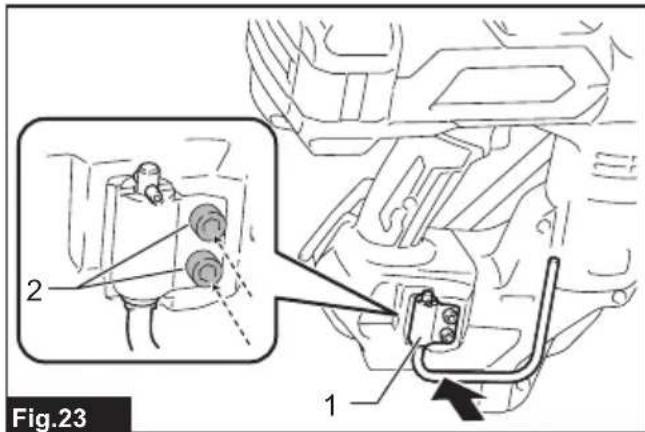
C-shaped hook
Aligning the two sets of bolt holes, place the C-shaped hook on the tool housing with the opening of the C-shaped hook faces upwards. Tighten the C-shaped hook with two hex bolts.
To remove the C-shaped hook, loosen the bolts and then take the hook out.
▶ Fig.23: 1. C-shaped hook 2. Hex bolts
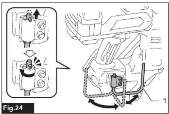
The C-shaped hook can be positioned open at 90-degree intervals.
Push and hold the hook upwards and swing it to your desired position.
▶ Fig.24: 1. C-shaped hook
Hex wrench storage
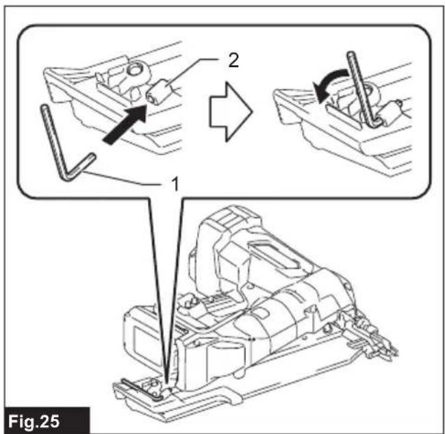
Keep the hex wrench supplied ready on the wrench holder while it is not in use.
▶ Fig.25: 1. Hex wrench 2. Wrench holder
OPERATION
Testing safety system
WARNING: Make sure all safety systems are in working order before operation. Failure to do so may cause personal injuries.
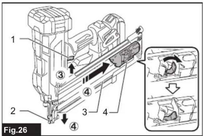
▶ Fig.26: 1. Switch trigger 2. Contact element 3. Magazine 4. Nail pusher
Test safety system as follows for possible fault or malfunction before operation.
- Remove the battery cartridge from the tool. Then unload all the nails left in the magazine.
- Install the battery cartridge in place and turn the tool on.
-
Pull the switch trigger without placing the contact element against the material.
-
Pull the nail pusher towards the magazine slit and hold it in place. Then place the contact element against the material without pulling the switch trigger.
If the tool works in case step 3 or 4 described above, safety system is not functioning properly. Stop using the tool immediately and ask your local Makita Service Center.
Driving nails
WARNING: Continue to place the contact element firmly on the material until the nail is driven completely. Unintentional firing may cause personal injuries.
CAUTION: Before installing the battery cartridge into the tool, always check to see that the switch trigger actuates properly and returns to the "OFF" position when released.
CAUTION: Do not drive nails on hard materials such as metal or the like. If the nail cannot penetrate the material, the nailer may be kicked back toward you and cause injury.
⚠️ CAUTION: Hold the tool firmly during operation.
NOTICE: The tool will not start fastening after five seconds no switch operation while either the switch trigger or the contact element is being solely actuated. Release the switch trigger or pull the contact element free from the workpiece, and then reposition the tool in place to restart fastening.
NOTE: If you drive nails continuously for a long time, the exhaust air will get hot due to the heat from the motor.
The tool employs two nailing actions; full sequential actuation and contact actuation.
NOTE: Only a single nailing mode (full sequential actuation) is available in some regions or countries. The switch design varies depending on your region of residence.
Full sequential actuation
In this mode, you can drive one nail by one sequential operation.
A workpiece contact and then a trigger need to be activated in a specific sequence to actuate the tool. Release and re-activate the switch controls in the same sequence to continue driving nails.
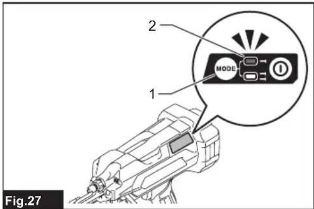
- Press and hold the main power button to turn on the tool.
- Make sure that the sequential actuation mode lamp lights up.
▶ Fig.27: 1. Actuation mode switch button
2. Sequential actuation mode lamp
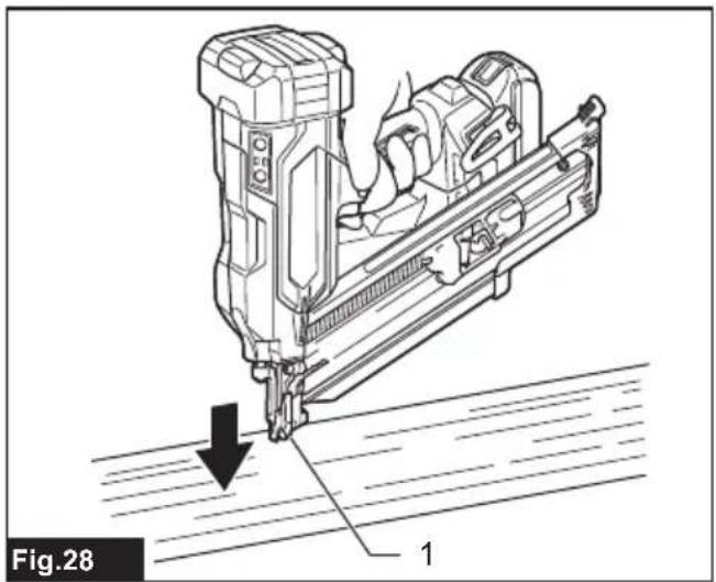
- Place the contact element flat on the material.
▶ Fig.28: 1. Contact element
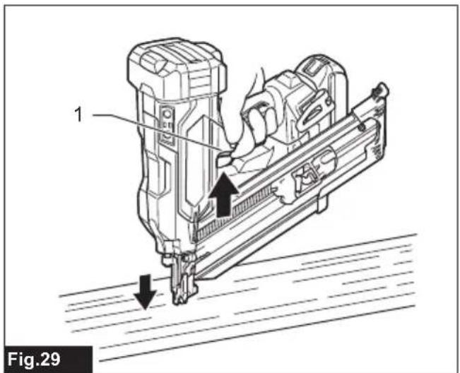
- Pull the switch trigger fully to drive a nail.
▶ Fig.29: 1. Switch trigger
- Release your finger from the switch trigger. Then lift the contact element up from the material.
To drive the next nail, repeat the steps 3 to 5 in the same sequence.
Contact actuation
Country specific
In this mode, you can choose either continuous or single nailing by following any sequences of the trigger operation.
A workpiece contact and a trigger can be activated in any sequences to actuate the tool. Release and re-activate the workpiece contact to continuously drive nails.
For a single nailing
- Press and hold the main power button to turn on the tool.
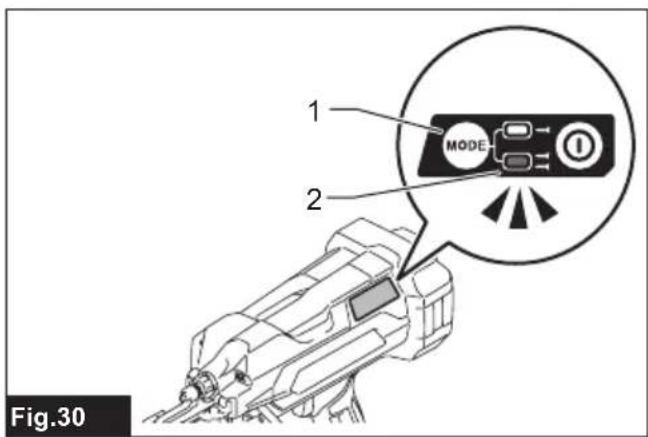
- Press and shortly hold the actuation mode switch button to select the contact actuation mode.
The contact actuation mode lamp lights up.
▶ Fig.30: 1. Actuation mode switch button 2. Contact actuation mode lamp
- Place the contact element flat on the material.
- Pull the switch trigger fully to drive a nail.
- Release your finger from the switch trigger. Then lift the contact element up from the material.
To drive the next nail, repeat the steps 3 to 5 in the same sequence.
For a continuous nailing
- Press and hold the main power button to turn on the tool.
- Press and shortly hold the actuation mode switch button to select the contact actuation mode.
The contact actuation mode lamp lights up.
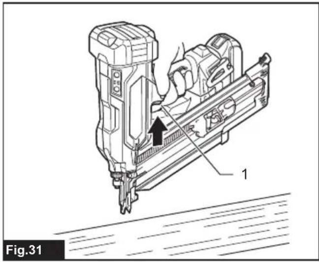
- Pull the switch trigger.
▶ Fig.31: 1. Switch trigger - Place the contact element flat on the material to drive a nail.
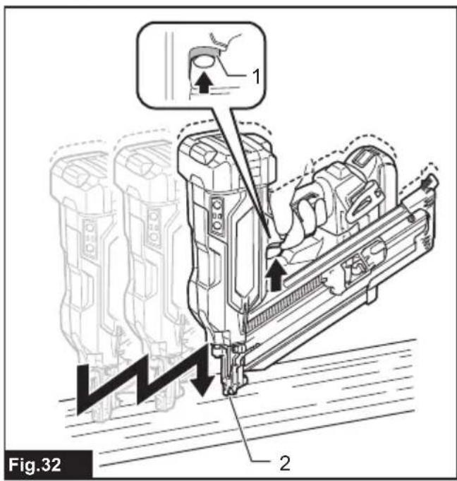
- Move the tool to the next areas with the switch trigger pulled, and place the contact element flat on the material to drive following nails.
▶ Fig.32: 1. Switch trigger 2. Contact element
Anti dry fire mechanism
When the remaining nails in the magazine decrease to 7 - 9 pieces for model DBN900 / 6 - 7 pieces for model DBN901, the switch can no longer be actuated and the tool stops firing. Insert a new strip of nails in the magazine before restarting operation.
Removing jammed nails
WARNING: Always make sure that the battery cartridge is removed before removing jammed nails.
When a nail jamming occurs, look over closely the nail feeding and driving unit. Jams tend to be caused by nails wedged between the nail driver and the driver guide.
Clearing a jam
WARNING: Do not push on the nail driver forcibly. Do not strike the nail driver and nails with any hand tools to clear jams. Mind that the tool is charged with compressed air and the pressure is maintained inside. Failure to follow the safety precautions in the manual can result in serious injury.
WARNING: Never point the tool at yourself or other persons nearby when clearing jams. Failure to do so may cause a risk of injury by misfiring since the tool is charged with compressed air in a factory sealed chamber.
CAUTION: To address frequent jamming or hard-to-clear jamming situations, consult your local Makita Service Center.
- Remove the battery cartridge from the tool.
- Take out all the nails left in the magazine.
- Clear a jam using pliers or the like.
NOTE: Dismount the magazine from the tool if jamming occurs inside the nail feeding and driving unit.
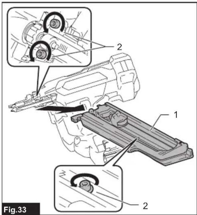
- Loosen and remove the bolts that secure the magazine using the hex wrench. Then lift the free end of the magazine slightly and pull it straight out.
▶ Fig.33: 1. Magazine 2. Bolts
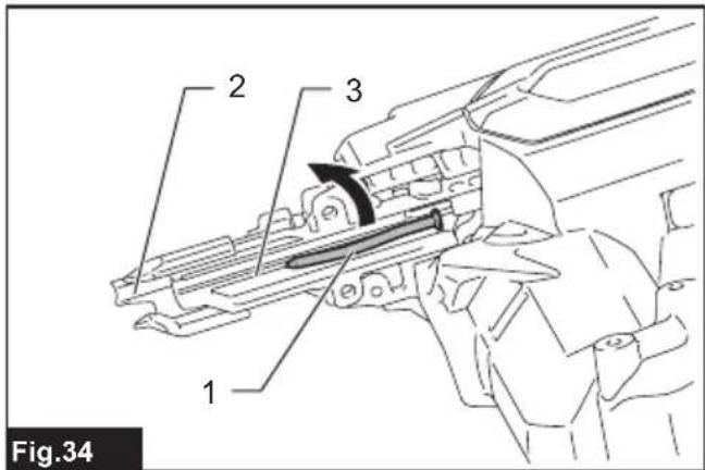
5. Clear jammed nails in the nail exit opening or through the driver guide.
Use pliers to bend the jammed nail so that the nail head comes out of the slot in the driver guide. Then remove the jammed nail.
▶ Fig.34: 1. Jammed nail 2. Nail exit opening 3. Driver guide
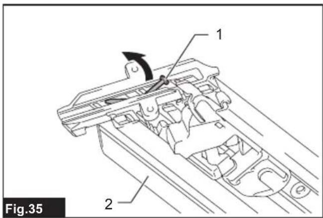
A jamming may occur at the nail feeding slot in the magazine. Use pliers to bend the jammed nail so that the nail head comes out of the slot in the magazine. Then remove the jammed nail.
▶ Fig.35: 1. Jammed nail 2. Magazine
6. Insert the lock plate in the magazine into the lock groove in the driver guide at an angle. Align the bolt holes in the magazine with those in the driver guide.
Tighten the magazine on the tool body with the bolts.
Initializing driver position
The nail driver may not be positioned correctly behind the nail to be driven next after a nail jamming or under low battery condition. Always perform initialization steps before you restart operation.
- Remove the battery cartridge from the tool.
- Take out all the nails left in the magazine.
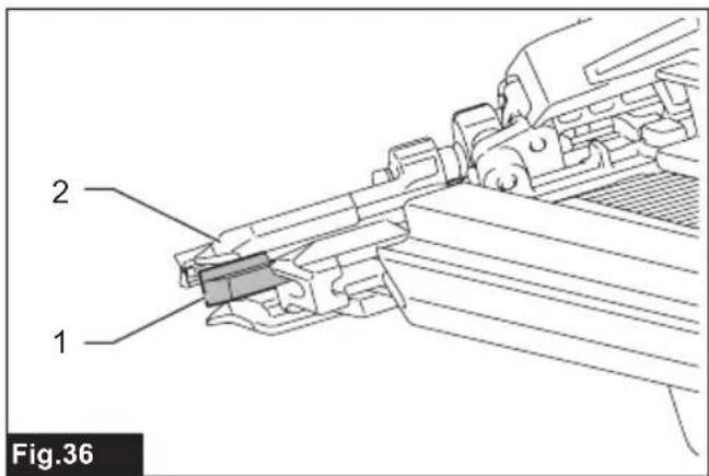
- Observe the nail driver position.
If you see the driver tip out of the contact top, the contact element cannot correctly be actuated during initialization.
▶ Fig.36: 1. Nail driver 2. Contact top
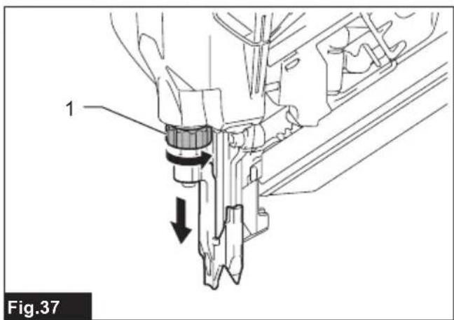
Turn the adjuster to set the shallowest nailing depth so that the contact element functions properly.
▶ Fig.37: 1. Nailing depth adjuster
- Install the battery cartridge in place and turn the tool on.
- Pull the nail pusher towards the magazine slit and hold it in place. Then place the contact element against the material that can be damaged.
- Pull the switch trigger fully, with the contact element actuated, to reset the driver position.
▶ Fig.38: 1. Nail pusher 2. Magazine slit 3. Contact element 4. Switch trigger
The driver position will be initialized correctly.
- Remove the battery cartridge from the tool. Reload the nail strip in the magazine. Place the battery cartridge back into the tool.
MAINTENANCE
WARNING: Do not disassemble this tool. This tool is sealed with compressed air and disassembly may result in serious injury.

natural_image
Silhouette of a person with sound waves radiating outward, symbolizing communication or music (no text or symbols present)⚠️CAUTION: Always be sure that the tool is switched off and the battery cartridge is removed before attempting to perform inspection or maintenance.
NOTICE: Never use gasoline, benzine, thinner, alcohol or the like. Discoloration, deformation or cracks may result.
To maintain product SAFETY and RELIABILITY, repairs, any other maintenance or adjustment should be performed by Makita Authorized or Factory Service Centers, always using Makita replacement parts.
Preventive maintenance
Thoroughly clean and inspect moving components (i.e., contact element, nail pusher, etc.) on a regular basis, keeping them free of dust and dirt that may accumulate over time.
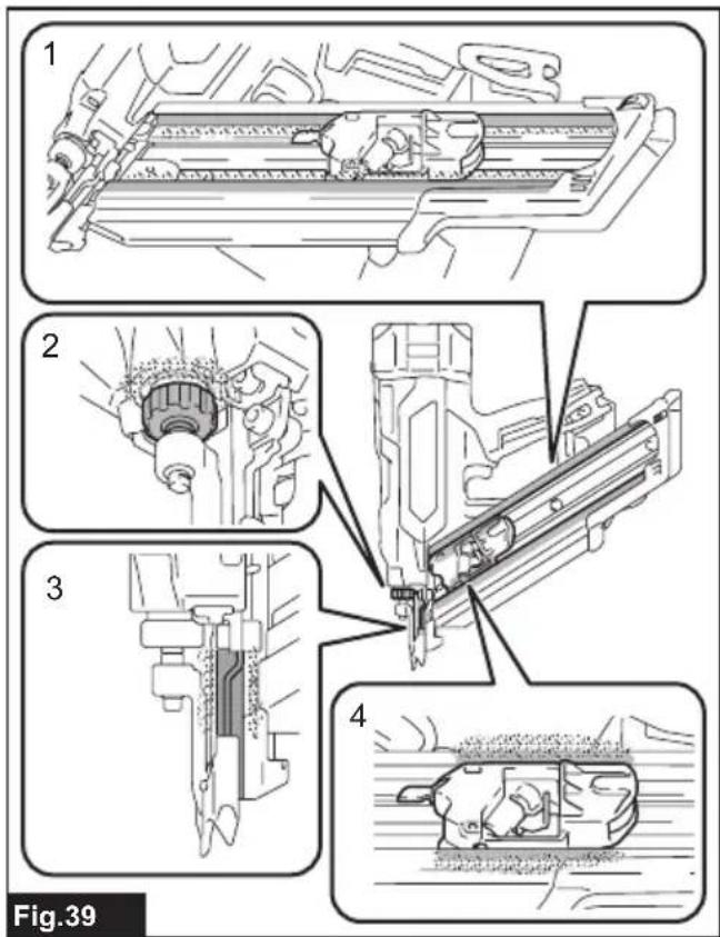
NOTE: If the moving and sliding components, as following illustrated, seem to work poorly or inefficiently, blow any dirt and dust adhered around off and then wipe clean.
▶ Fig.39: 1. Nail feeding rails 2. Nailing depth adjuster 3. Contact element 4. Nail pusher
OPTIONAL ACCESSORIES
CAUTION: These accessories or attachments are recommended for use with your Makita tool specified in this manual. The use of any other accessories or attachments might present a risk of injury to persons. Only use accessory or attachment for its stated purpose.
If you need any assistance for more details regarding these accessories, ask your local Makita Service Center.
- Nails
• Extended capacity magazines
• Makita genuine battery and charger
NOTE: Some items in the list may be included in the tool package as standard accessories. They may differ from country to country.
SPÉCIFICATIONS
▶ Fig.31: 1. Gâchette
natural_image
Silhouette of a human head with radiating lines and musical notes around (no text or symbols)natural_image
Silhouette of a person with sound waves radiating outward, symbolizing communication or music (no text or symbols present)natural_image
Silhouette of a person with sound waves radiating outward, symbolizing communication or music (no text or symbols present)⚠ WAARSCHUWING: Draag gehoorbescherming.
VEILIGHEIDSWAAR- SCHUWINGEN
▶ Fig.18: 1. Neusadapter 2. Contactschoen
natural_image
Silhouette of a human head with radiating lines and musical notes around (no text or symbols)OPTIONELE ACCESSOIRES
▶ Fig.25: 1. Llave hexagonal 2. Portallaves
OPERACIÓN
▶ Fig.29: 1. Gatillo interruptor
▶ Fig.31: 1. Gatillo interruptor