
DW631K - Drill DEWALT - Free user manual and instructions
Find the device manual for free DW631K DEWALT in PDF.

| Product type | Laminate trimmer (biscuit joiner) |
| Brand | DeWALT |
| Model | DW631K |
| Supply voltage | 230 V |
| Power input | 600 W |
| Power output | 350 W |
| No-load speed | 30,000 rpm |
| Maximum plunge depth | 32 mm |
| Collets supplied | 6 mm, 6.35 mm, 8 mm |
| Maximum cutter diameter | 36 mm |
| Weight | 2.8 kg |
| Sound pressure level (LpA) | 91 dB(A) |
| Sound power level (LwA) | 99 dB(A) |
| Vibration (weighted acceleration) | 4.8 m/s² |
| Double insulation | Yes (class II) |
| Hearing protection recommended | Yes (above 85 dB(A)) |
| Warranty | 1 year (parts and labor) + 30 days satisfaction guarantee |
| Package contents | Trimmer, 3 collets, wrench, copying guide, 2 guide bars, trimming plate, carrying case |
| Motor type | Double insulated electric motor |
Frequently Asked Questions - DW631K DEWALT
User questions about DW631K DEWALT
0 question about this device. Answer the ones you know or ask your own.
Ask a new question about this device
Download the instructions for your Drill in PDF format for free! Find your manual DW631K - DEWALT and take your electronic device back in hand. On this page are published all the documents necessary for the use of your device. DW631K by DEWALT.
USER MANUAL DW631K DEWALT
A


C
B
natural_image
Technical line drawing of a mechanical device with no visible text or symbolsD
E1


natural_image
Mechanical assembly diagram showing a bracket with gears and a numbered component (no text or symbols)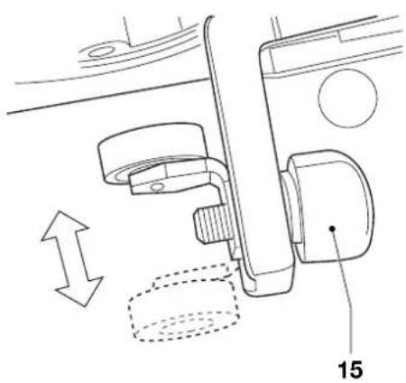
natural_image
Technical line drawing of a mechanical assembly with no visible text or symbolsE3
E2
natural_image
Technical line drawing of a mechanical device with labeled parts (no readable text or symbols)E4
E5


natural_image
Technical line drawing of a mechanical part with a circular hole and flange (no text or symbols)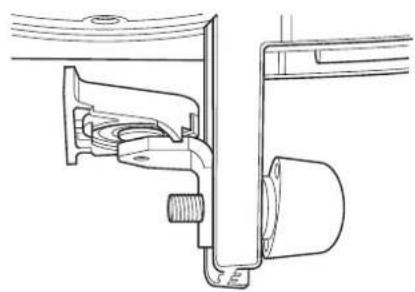
natural_image
Technical line drawing of a mechanical assembly with no visible text or symbolsE6
E7

natural_image
Technical line drawing of a mechanical device with hoses and connectors (no text or symbols)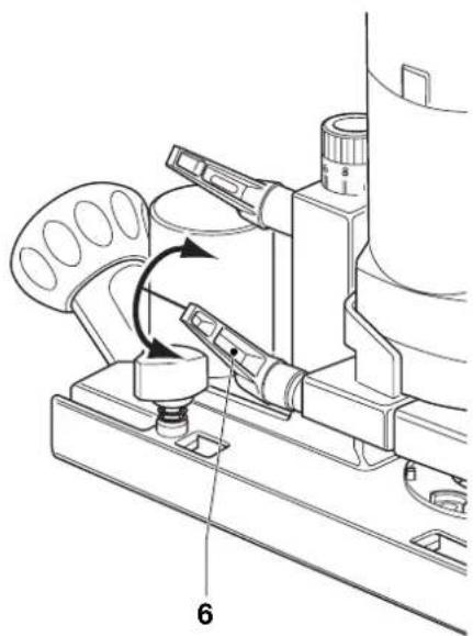
natural_image
Technical line drawing of a mechanical device with a rotating lever and labeled component (no text or symbols present)F
G


natural_image
Technical line drawing of a vacuum cleaner with labeled component (no text or symbols present)|
H
natural_image
Technical line drawing of a mechanical assembly with gears and shafts (no text or symbols)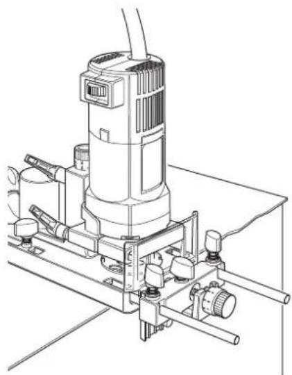
natural_image
Technical line drawing of a mechanical device with no visible text or symbolsJ1
J2
DANSK
LAMINATFRÆSER DW631K
Tillykke!
You have chosen a DeWALT Power Tool. Years of experience, thorough product development and innovation make DeWALT one of the most reliable partners for professional Power Tool users.
Table of contents
| Technical data en - 1 |
| EC-Declaration of conformity en - 1 |
| Safety instructions en - 2 |
| Package contents en - 3 |
| Description en - 3 |
| Electrical safety en - 3 |
| Mains plug replacement (U.K. & Ireland only) en - 3 |
| Using an extension cable en - 4 |
| Assembly and adjustment en - 4 |
| Instructions for use en - 5 |
| Maintenance en - 5 |
| Guarantee en - 6 |
Technical data
| DW631K | |
| Voltage V 230 | |
| Power input | W 600 |
| Power output | W 350 |
| No-load speed | min ^-1 30,000 |
| Plunge | mm 32 |
| Collet size | mm 6, 6.35, 8 |
| Cutters diameter, max. | mm 36 |
| Weight | kg 2.8 |
| Fuses: | |
| Europe | 230 V tools 10 Amperes, mains |
| U.K. & Ireland | 230 V tools 13 Amperes, in plugs |
The following symbols are used throughout this manual:

Denotes risk of personal injury, loss of life or damage to the tool in case of non-observance of the instructions in this manual.

Denotes risk of electric shock.
EC-Declaration of conformity

DW631K
DeWALT declares that these Power Tools have been designed in compliance with: 98/37/EEC, 89/336/EEC, 73/23/EEC, EN 50144, EN 55014-2, EN 55014, EN 61000-3-2 & EN 61000-3-3.
For more information, please contact D=WALT at the address below, or refer to the back of the manual.
Level of sound pressure according to 86/188/EEC & 98/37/EEC, measured according to EN 50144:
| DW631K | |||
| L_pA | (sound pressure) | dB(A)^* | 91 |
| L_wA | (acoustic power) | dB(A) | 99 |
* at the operator's ear

Take appropriate measures for the protection of hearing if the sound pressure of 85 dB(A) is exceeded.
Weighted root mean square acceleration value according to EN 50144:
| DW631K | |
| 4.8 m/s2 |
Director Engineering and Product Development Horst Großmann
X. fopsmann
When using Power Tools, always observe the safety regulations applicable in your country to reduce the risk of fire, electric shock and personal injury. Read the following safety instructions before attempting to operate this product. Keep these instructions in a safe place!
General
1 Keep work area clean Cluttered areas and benches can cause accidents.
2 Consider work area environment Do not expose Power Tools to humidity. Keep work area well lit. Do not use Power Tools in the presence of flammable liquids or gases.
3 Guard against electric shock Prevent body contact with earthed surfaces (e.g. pipes, radiators, cookers and refrigerators). For use under extreme conditions (e.g. high humidity, when metal swarf is being produced, etc.) electric safety can be improved by inserting an isolating transformer or a (FI) earth-leakage circuit-breaker.
4 Keep children away Do not let children come into contact with the tool or extension cord. Supervision is required for those under 16 years of age.
5 Extension cords for outdoor use When the tool is used outdoors, always use extension cords intended for outdoor use and marked accordingly.
6 Store idle tools When not in use, Power Tools must be stored in a dry place and locked up securely, out of reach of children.
7 Dress properly Do not wear loose clothing or jewellery. They can be caught in moving parts. Preferably wear rubber gloves and non-slip footwear when working outdoors. Wear protective hair covering to keep long hair out of the way.
8 Wear safety goggles Also use a face or dust mask in case the operations produce dust or flying particles.
9 Beware of maximum sound pressure Take appropriate measures for the protection of hearing if the sound pressure of 85 dB(A) is exceeded.
10 Secure workpiece Use clamps or a vice to hold the workpiece. It is safer and it frees both hands to operate the tool.
11 Do not overreach Keep proper footing and balance at all times.
12 Avoid unintentional starting Do not carry the plugged-in tool with a finger on the switch. Be sure that the switch is released when plugging in.
13 Stay alert Watch what you are doing. Use common sense. Do not operate the tool when you are tired.
14 Disconnect tool Shut off power and wait for the tool to come to a complete standstill before leaving it unattended. Unplug the tool when not in use, before servicing or changing accessories.
15 Remove adjusting keys and wrenches Always check that adjusting keys and wrenches are removed from the tool before operating the tool.
16 Use appropriate tool The intended use is described in this instruction manual. Do not force small tools or attachments to do the job of a heavy-duty tool. The tool will do the job better and safer at the rate for which it was intended.
Warning! The use of any accessory or attachment or performance of any operation with this tool, other than those recommended in this instruction manual may present a risk of personal injury.
17 Do not abuse cord Never carry the tool by its cord or pull it to disconnect from the socket. Keep the cord away from heat, oil and sharp edges.
18 Maintain tools with care Keep the tools in good condition and clean for better and safer performance. Follow the instructions for maintenance and changing accessories. Inspect the tool cords at regular intervals and, if damaged, have them repaired by an authorized DeWALT repair agent. Inspect the extension cords periodically and replace them if damaged. Keep all controls dry, clean and free from oil and grease.
19 Check for damaged parts Before using the tool, carefully check it for damage to ensure that it will operate properly and perform its intended function.
ENGLISH
Check for misalignment and seizure of moving parts, breakage of parts and any other conditions that may affect its operation. Have damaged guards or other defective parts repaired or replaced as instructed.
Do not use the tool if the switch is defective. Have the switch replaced by an authorized DeWALT repair agent.
20 Have your tool repaired by an authorized DEWALT repair agent
This Power Tool is in accordance with the relevant safety regulations. To avoid danger, electric appliances must only be repaired by qualified technicians.
Additional safety rules for cutters
- Always use cutters with a shank diameter corresponding to the size of the collet installed in your tool.
• Always use cutters suitable for a speed of 30.000 min^-1 and marked accordingly. - Never use cutters with a diameter exceeding the maximum diameter indicated in the technical data.
Package contents
The package contains:
1 Laminate trimmer
3 Collets (6 mm, 6.35 mm, 8 mm)
1 Wrench 17/19
1 Copy follower
2 Guide rods
1 Trimming plate
1 Kitbox
1 Instruction manual
1 Exploded drawing
- Check for damage to the tool, parts or accessories which may have occurred during transport.
• Take the time to thoroughly read and understand this manual prior to operation.
Description (fig. A)
Your laminate trimmer DW631K has been designed for trimming wood and plastic laminates.
1 On/off-switch
2 Depth stop adjuster
3 Plunge lock
4 Trimming base
5 Chip shield
6 Motor clamping lever
7 Guide knob
8 Guide rods
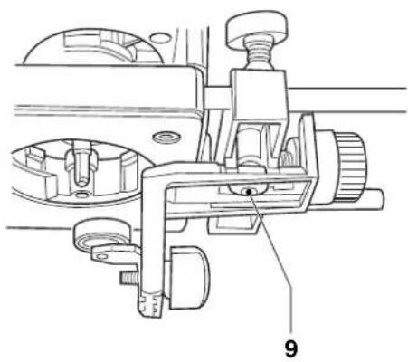
9 Copy follower
10 Clamping knob for guide rods
11 Dust extraction spout
Electrical safety
The electric motor has been designed for one voltage only. Always check that the power supply corresponds to the voltage on the rating plate.

Your DEWALT tool is double insulated in accordance with EN 50144; therefore no earth wire is required.
Mains plug replacement (U.K. & Ireland only)
- Should your mains plug need replacing and you are competent to do this, proceed as instructed below. If you are in doubt, contact an authorized DeWALT repair agent or a qualified electrician.
- Disconnect the plug from the supply.
- Cut off the plug and dispose of it safely; a plug with bared copper conductors is dangerous if engaged in a live socket outlet.
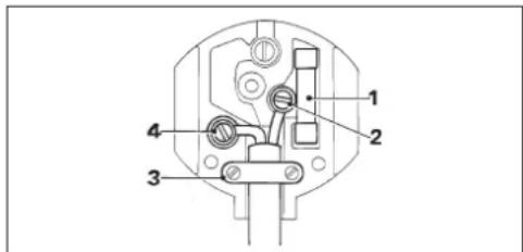
- Only fit 13 Amperes BS1363A approved plugs fitted with the correctly rated fuse (1).
- The cable wire colours, or a letter, will be marked at the connection points of most good quality plugs. Attach the wires to their respective points in the plug (see below). Brown is for Live (L) (2) and Blue is for Neutral (N) (4).
- Before replacing the top cover of the mains plug ensure that the cable restraint (3) is holding the outer sheath of the cable firmly and that the two leads are correctly fixed at the terminal screws.

Never use a light socket. Never connect the live (L) or neutral (N) wires to the earth pin marked E or
Using an extension cable
If an extension cable is required, use an approved extension cable suitable for the power input of this tool (see technical data). The minimum conductor size is 1.5 mm^2 . When using a cable reel, always unwind the cable completely.
Also refer to the table below.
| Conductor size (mm2) Cable rating (Amperes) | |
| 0.75 6 | |
| 1.00 10 | |
| 1.50 15 | |
| 2.50 20 | |
| 4.00 25 | |
| Cable length (m) | |
| 7.5 15 25 30 45 60 | |
| Voltage Amperes Cable rating (Amperes) | |
| 230 0 - 2.0 6 6 6 6 6 6 | |
| 2.1 - 3.4 6 6 6 6 6 6 | |
| 3.5 - 5.0 6 6 6 6 10 15 | |
| 5.1 - 7.0 | 10 10 10 10 15 15 |
| 7.1 - 12.0 | 15 15 15 15 20 20 |
| 12.1 - 20.0 | 20 20 20 20 25 |
Assembly and adjustment

Prior to assembly and adjustment always unplug the tool.
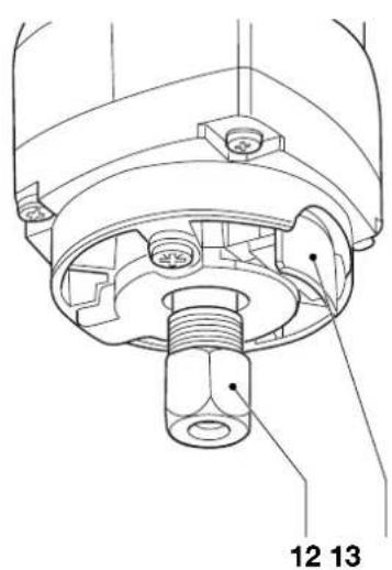
Replacing the collet assembly (fig. B)
Your laminate trimmer is supplied with an 8 mm collet fitted to the tool. Two other precision collets are also available to suit the cutter used. The collet and the collet nut are inseparable.
- Keep the spindle lock button (13) depressed and loosen the collet nut (12) completely.
- Remove the collet assembly.
- Fit a new assembly and screw the collet nut onto the spindle. Do not tighten.
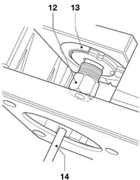
Inserting and removing a cutter (fig. C)
- Keep the spindle lock button (13) depressed and loosen the collet nut (12) with the wrench.
- Insert a cutter (14) and tighten the collet nut.

Never tighten the collet nut without a cutter in the collet.
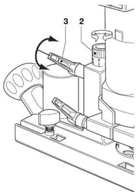
Setting the depth of cut (fig. D)
- Turn the plunge lock (3) counterclockwise to release the carriage.
- Set the required depth of cut by turning the depth stop adjuster (2) to the desired setting on the scale.
- To fine-tune the depth of cut, use the ring on the adjuster.
- Tighten the plunge lock (3).
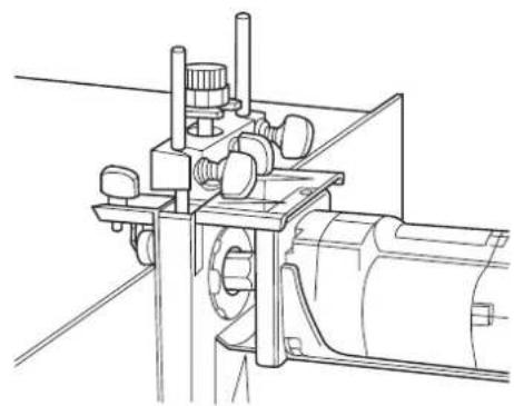
Mounting and adjusting the copy follower (fig. A, E1 - E7)
The copy follower (9) is used to trim along shaped edges (fig. E1 & E2).
- Mount the copy follower (9) by inserting the guide rods (8) into the corresponding holes in the trimming base (4) (fig. A).
Height
- Loosen the adjustment lever (15) and move the copy follower up or down as required (fig. E3).
- Tighten the adjustment lever.
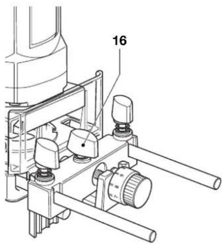
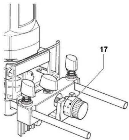
Side distance
- Loosen the clamping nut (16) and set the side distance using the fine adjuster (17) (fig. E4 & E5).
- Tighten the clamping nut again.
Straight guide or guide roller
The straight guide (18) is used to avoid copying the imperfections in the edges of the base material when using the copy follower (9).
- For straight edges, place the straight guide onto the ball bearing assembly (fig. E7).
- For shaped edges, remove the straight guide from the ball bearing assembly.
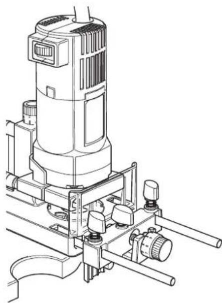
Mounting the trimming plate (fig. F)
The trimming plate (19) is used when trimming laminates which are higher than the board surface.
- Attach the trimming plate to the tool base as shown.
Removing the motor from the base (fig. G)
- To remove the motor from the base, loosen the motor clamping lever (6).
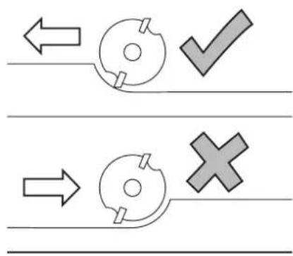
Feed direction (fig. H)
• Always feed the workpiece against the rotating cutter as shown in fig. H.
ENGLISH

Connecting a dust extractor (fig. A)
- Whenever possible, connect a dust extraction device designed in accordance with the relevant regulations regarding dust emission.
- Connect a dust extractor hose to the dust extraction spout (11).
- Connect the other end of the hose to a suitable dust extractor.
Instructions for use

Always observe the safety instructions and applicable regulations.
Prior to operation:
- Check that the cutter is correctly installed in the collet.
- Set the cutting depth.
- Connect a dust extractor.
• Always make sure the motor is locked to the base before switching on.
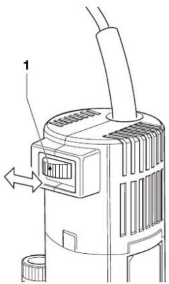
Switching on and off (fig. A)
- To switch the tool on, set the switch to the I position.
- To switch the tool off, set the switch to the O position.
Trimming with ball bearing or pilot cutters
- Remove the copy follower.
- Switch the tool on.
- Move the tool at constant speed, keeping the ball bearing or pilot cutter firmly against the workpiece.
- Switch the tool off.
Trimming shaped edges
• Install the copy follower when using cutters without ball bearing or pilot.
- Adjust the copy follower as described above.
- Switch the tool on.
- Move the tool at constant speed, keeping the ball bearing or pilot cutter firmly against the workpiece.
- Switch the tool off.
Trimming straight edges
• Install the straight guide on the copy follower as described above.
• Proceed as for shaped edges.
It is also possible to trim straight edges using the copy follower only.
Consult your dealer for further information on the appropriate accessories.
Maintenance
Your DeWALT Power Tool has been designed to operate over a long period of time with a minimum of maintenance. Continuous satisfactory operation depends upon proper tool care and regular cleaning.

Lubrication
Your power tool requires no additional lubrication.

Cleaning
Keep the ventilation slots clear and regularly clean the housing with a soft cloth.

Unwanted tools and the environment
Take your tool to an authorized DEWALT repair agent where it will be disposed of in an environmentally safe way.
GUARANTEE
• 30 DAY NO RISK SATISFACTION GUARANTEE •
If you are not completely satisfied with the performance of your DeWALT tool, simply return it within 30 days, complete as purchased, to the point of purchase, for a full refund or exchange. Proof of purchase must be produced.
• ONE YEAR FREE SERVICE CONTRACT •
If you need maintenance or service for your DeWALT tool, in the 12 months following purchase, it will be undertaken free of charge at an authorized DeWALT repair agent. Proof of purchase must be produced. Includes labour and spare parts for Power Tools. Excludes accessories.
• ONE YEAR FULL WARRANTY •
If your DeWALT product becomes defective due to faulty materials or workmanship within 12 months from the date of purchase, we guarantee to replace all defective parts free of charge or, at our discretion, replace the unit free of charge provided that:
• The product has not been misused.
• Repairs have not been attempted by unauthorized persons.
• Proof of purchase date is produced.
This guarantee is offered as an extra benefit and is additional to consumers statutory rights.
For the location of your nearest authorized D=WALT repair agent, please use the appropriate telephone number on the back of this manual. Alternatively, a list of authorized D=WALT repair agents and full details on our after-sales service are available on the Internet at www.2helpU.com.
ESPAÑOL
RIBETEADORA DE LAMINADOS DW631K
¡Enhorabuena!
Director Engineering and Product Development Horst Großmann

L'emballage contient:
(Isolation double) - outils
Director Engineering and Product Development Horst Großmann

DeWALT, Richard-Klinger-Straße 40, D-65510, Idstein, Duitsland
TILSKJÆRINGSMASKIN FOR LAMINAT DW631K
Gratulerer!
Director Engineering and Product Development Horst Großmann

DeWALT, Richard-Klinger-Straße 40, D-65510, Idstein, Tyskland
Sikkerhetsforskrifter
Director Engineering and Product Development Horst Großmann

DeWALT, Richard-Klinger-Straße 40, D-65510, Idstein, Alemanha
Director Engineering and Product Development Horst Großmann

Director Engineering and Product Development Horst Großmann

DeWALT, Richard-Klinger-Straße 40, D-65510, Idstein, Tyskland
Säkerhetsinstruktioner
TABAKA KESİCİ DW631K
Tebrikler!
- DANSK
- LAMINATFRÆSER DW631K
- Tillykke!
- EC-Declaration of conformity
- DW631K
- General
- ENGLISH
- Have your tool repaired by an authorized DEWALT repair agent
- Additional safety rules for cutters
- Package contents
- Description (fig. A)
- Electrical safety
- Mains plug replacement (U.K. & Ireland only)
- Using an extension cable
- Assembly and adjustment
- Replacing the collet assembly (fig. B)
- Inserting and removing a cutter (fig. C)
- Setting the depth of cut (fig. D)
- Mounting and adjusting the copy follower (fig. A, E1 - E7)
- Height
- Side distance
- Straight guide or guide roller
- Mounting the trimming plate (fig. F)
- Removing the motor from the base (fig. G)
- Feed direction (fig. H)
- Connecting a dust extractor (fig. A)
- Instructions for use
- Prior to operation:
- Switching on and off (fig. A)
- Trimming with ball bearing or pilot cutters
- Trimming shaped edges
- Trimming straight edges
- Maintenance
- Lubrication
- Cleaning
- Unwanted tools and the environment
- GUARANTEE
- • 30 DAY NO RISK SATISFACTION GUARANTEE •
- • ONE YEAR FREE SERVICE CONTRACT •
- • ONE YEAR FULL WARRANTY •
- ESPAÑOL
- RIBETEADORA DE LAMINADOS DW631K
- ¡Enhorabuena!
- TILSKJÆRINGSMASKIN FOR LAMINAT DW631K
- Gratulerer!
- Sikkerhetsforskrifter
- Säkerhetsinstruktioner
- TABAKA KESİCİ DW631K
- Tebrikler!
Brand : DEWALT
Model : DW631K
Category : Drill