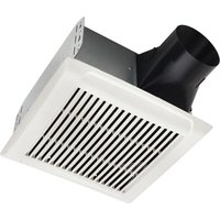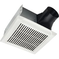
Flex AERN80BC - Fan NuTone - Free user manual and instructions
Find the device manual for free Flex AERN80BC NuTone in PDF.


User questions about Flex AERN80BC NuTone
0 question about this device. Answer the ones you know or ask your own.
Ask a new question about this device
Download the instructions for your Fan in PDF format for free! Find your manual Flex AERN80BC - NuTone and take your electronic device back in hand. On this page are published all the documents necessary for the use of your device. Flex AERN80BC by NuTone.
USER MANUAL Flex AERN80BC NuTone
Roomside / Flex™ Series Fan READ AND SAVE THESE INSTRUCTIONS
For Warranty Statement, Service Parts, Technical Support, or to Register your product, please visit our website or call: In the United States - Broan-NuTone.com 800-558-1711. In Canada - Broan-NuTone.ca 800-567-3855.
WARNING
TO REDUCE THE RISK OF FIRE, ELECTRIC SHOCK, OR INJURY TO PERSONS, OBSERVE THE FOLLOWING:
- Use this unit only in the manner intended by the manufacturer. If you have questions, contact the manufacturer at the address or telephone number listed in the warranty.
- Before servicing or cleaning unit, switch power off at service panel and lock the service disconnecting means to prevent power from being switched on accidentally. When the service disconnecting means cannot be locked, securely fasten a prominent warning device, such as a tag, to the service panel.
- Installation work and electrical wiring must be done by a qualified person(s) in accordance with all applicable codes and standards, including fi re-rated construction codes and standards.
- Suffi cient air is needed for proper combustion and exhausting of gases through the fl ue (chimney) of fuel burning equipment to prevent backdrafting. Follow the heating equipment manufacturer's guideline and safety standards such as those published by the National Fire Protection Association (NFPA), and the American Society for Heating, Refrigeration and Air Conditioning Engineers (ASHRAE), and the local code authorities.
- When cutting or drilling into wall or ceiling, do not damage electrical wiring and other hidden utilities.
- Ducted fans must always be vented to the outdoors.
- Acceptable for use over a tub or shower when connected to a GFCI (Ground Fault Circuit Interrupter) - protected branch circuit (ceiling installation only).
- This unit must be grounded.
CAUTION
- For general ventilating use only. Do not use to exhaust hazardous or explosive materials and vapors.
- This product can be installed in a wall if mounted 8-ft. or more above the floor.
- To avoid motor bearing damage and noisy and/or unbalanced impellers, keep drywall spray, construction dust, etc. off power unit.
- Please read specification label on product for further information and requirements.
CLEANING & MAINTENANCE
For quiet and efficient operation, long life, and attractive appearance - lower or remove grille and vacuum interior of unit with the dusting brush attachment.
The motor is permanently lubricated and never needs oiling. If the motor bearings are making excessive or unusual noises, replace the blower assembly (includes motor and impeller).
OPERATION
Use an on/off switch to operate the fan.
Refer to Broan's catalog for a complete line of accessories/controls to effectively adapt these fans to your requirements.
text_image
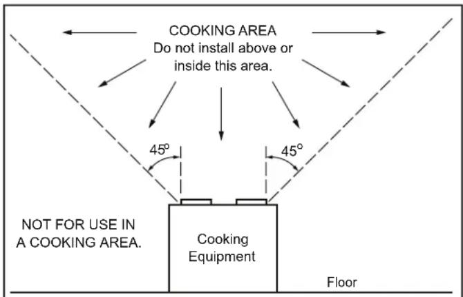
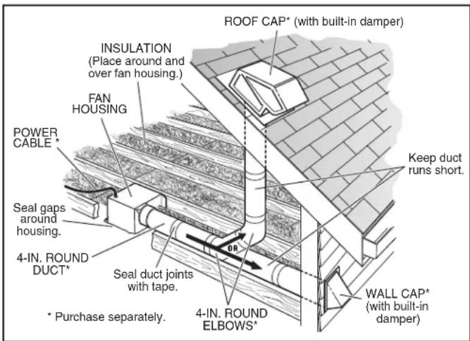
COOKING AREA Do not install above or inside this area. 45° 45° NOT FOR USE IN A COOKING AREA. Cooking Equipment FloorIMPORTANT - The ducting from this fan to the outside of the building has a strong effect on the air flow, noise and energy use of the fan. Use the shortest, straightest duct routing possible for best performance, and avoid installing the fan with smaller ducts than recommended. Insulation around the ducts can reduce energy loss and inhibit mold growth. Fans installed with existing ducts may not achieve their rated airflow.
text_image
ROOF CAP* (with built-in damper) INSULATION (Place around and over fan housing.) FAN HOUSING POWER CABLE * Seal gaps around housing. 4-IN. ROUND DUCT* * Purchase separately. SEAL DUCT joints with tape. 4-IN. ROUND ELBOWS* WR Keep duct runs short. WALL CAP* (with built-in damper)OPTION - To mount housing anywhere between ceiling framing: Use optional Hanger Bar Kit (sold separately from local distributors or website). Follow mounting instructions included with kit.
ALL INSTALLATIONS
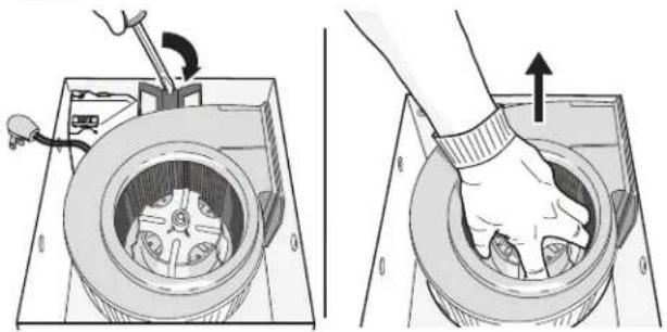
1 Remove all packing material, unplug and remove blower from fan housing.
natural_image
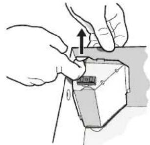
Two-panel illustration showing a hand operating a mechanical device with a rotating arm and a close-up of the interior (no text or symbols)2 Remove wiring panel from fan housing (if already installed).
natural_image
Illustration of hands installing a component with an arrow indicating upward motion (no text or symbols present)Some models only:
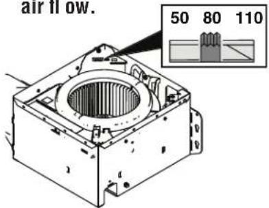
Select 50, 80 or 110
CFM based on your room
size and desired
air flow.
text_image
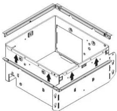
air flow. 50 80 1104 Some models only: A pair of fl anges may be attached to housing if desired or required.
Snap both fl ange pieces under rolled-over edge of housing (all four sides).
natural_image
Technical line drawing of a mechanical housing or enclosure with mounting holes and internal components (no text or symbols)For Retrofi t Installation - Skip to Page 3.
NEW INSTALLATION
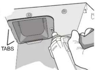
5 Attach damper/duct connector to fan housing.
Push connector through opening from inside of housing.
Engage tabs and secure with screw from parts bag.
text_image
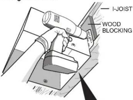
TABS6 Mount housing to ceiling structure.
Make sure bottom of housing will be fl ush with fi nished ceiling.
For proper location using 1/2" ceiling material: Bend out housing tabs (on outside of housing) to fit against bottom of joist.
Secure housing through mounting ears with appropriate fasteners. If mounting housing to I-joist, use wood blocking as shown.
text_image
I-JOIST WOOD BLOCKING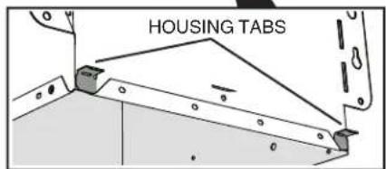
text_image
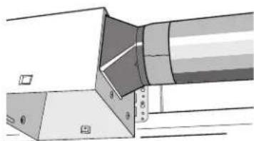
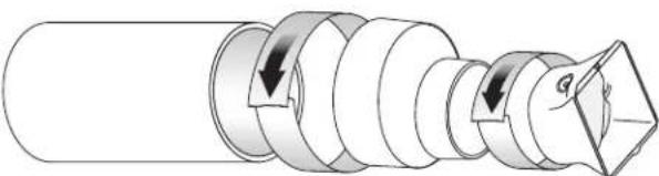
HOUSING TABS7 Connect 4-in. round duct.
natural_image
Technical diagram of a mechanical component with no visible text or symbolsA 4 to 6-inch duct expander is provided with select models.
natural_image
Diagram of a mechanical component with arrows indicating motion or force direction (no text or symbols)8
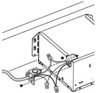
Connect wiring.
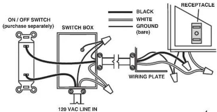
Connect power cable to wiring plate (from parts bag) using UL approved connector.
Connect house wiring to fan wiring. Refer to wiring diagram for connection
details. Use screw (from parts bag) to secure wiring plate to fan housing. Re-install wiring panel and secure with screw from parts bag.
natural_image
Technical line drawing of a mechanical or electrical assembly with wires and components (no text or symbols)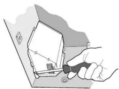
natural_image
Illustration of a hand using a tool to adjust or install a component into a box (no text or symbols visible)9
Finish ceiling.
Then continue with Step 10.
RETROFIT INSTALLATION
5
Remove old fan and prepare ceiling.
Enlarge ceiling opening (if necessary) to 9 ^3/4 " parallel to joist) by 10 ^1/2 " (perpendicular to joist). (Some models have a cut-out template on side of carton or on grille packaging materials.)
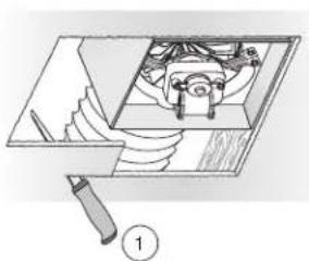
natural_image
Mechanical assembly diagram showing internal components and a tool handle (no text or labels)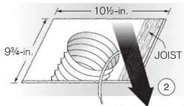
text_image
10½-in. 9¾-in. JOIST ②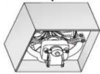
6
Fold mounting ears fl at against housing.
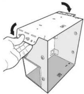
text_image
Diagram showing a hand interacting with a device labeled 'Attacked Box' with arrows indicating rotation or movement.Existing fan housings are typically attached to the structure:
- with screws, nails, or staples, which must be removed.
- with hangers or rails which are fastened to joists and must be removed along with housing.
A pry bar may be needed to remove the old housing.
Leave ductwork and wiring in place.
7
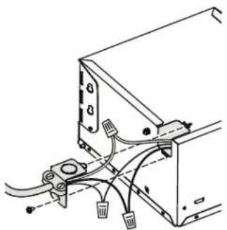
Connect wiring.
Connect power cable to wiring plate (from parts bag) using UL approved connector. Connect house wiring to fan wiring. Refer to wiring diagram for connection details. Use screw (from parts bag) to secure wiring plate to fan housing. Re-install wiring panel and secure with screw from parts bag.
natural_image
Technical line drawing of a mechanical or electrical component with wires and connectors (no text or symbols)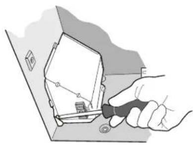
natural_image
Illustration of a hand using a tool to adjust or install a small electronic component (no text or symbols visible)8
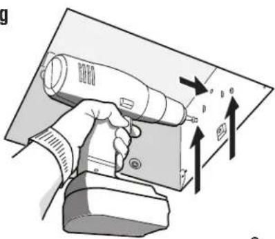
Mount fan to ceiling structure.
Mount housing to ceiling structure with appropriate fasteners in locations shown.
text_image
g p o r9
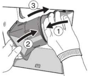
Connect 4-in. round duct.
①Pull existing ducting through housing discharge opening and ②tape ducting to duct connector. ③ Push connector/ducting back through opening. Engage tabs and ④ secure with screw from parts bag.
text_image
Diagram showing hand positioning of a device with numbered arrows indicating movement or positioning steps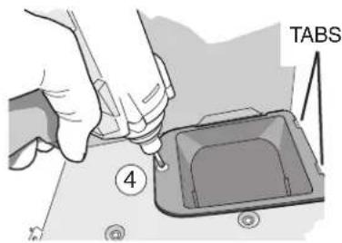
text_image
TABS ④Continue with Step 10.
ALL INSTALLATIONS
10
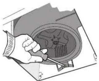
Install blower.
Re-install blower removed in Step 1. Secure blower with 2 screws from parts bag. Plug blower into black receptacle.
Flex™ Series Fan ONLY: Plug 5-wire plug into controller module.
natural_image
Illustration of a hand using a screwdriver to adjust or install a mechanical component (no text or symbols visible)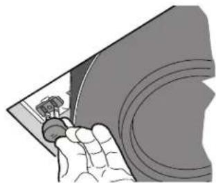
natural_image
Illustration of a hand holding a curved object with a small inset image (no text or symbols)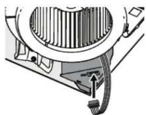
natural_image
Mechanical assembly diagram showing gear and housing components (no text or labels)Flex™ Series Fan ONLY
11
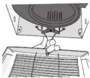
Install grille.
Squeeze grille springs and insert into slots in blower. Push grille up against ceiling.
natural_image
Technical line drawing of a sewing machine needle stitching a grille (no text or symbols)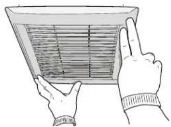
natural_image
Illustration of two hands holding a fan or vent with a grid pattern inside (no text or symbols)
natural_image
Diagram of a roof structure with curved lines and a downward arrow indicating direction (no text or symbols)If grille spring becomes dislodged from grille - snap it back into place as shown.
Depending upon model - your grille may look different.
WIRING DIAGRAM
text_image
ON / OFF SWITCH (purchase separately) SWITCH BOX 120 VAC LINE IN BLACK WHITE GROUND (bare) WIRING PLATE RECEPTACLE1103134C
natural_image
Diagram of a washing machine with hand operating the wheel (no text or labels)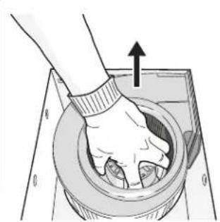
natural_image
Illustration of a hand pressing down on a circular mechanical component with an arrow indicating upward motion (no text or symbols)natural_image
Illustration of hands installing or adjusting a device component with an upward arrow (no text or symbols)natural_image
Technical line drawing of a mechanical housing or enclosure with mounting holes and internal components (no text or symbols)natural_image
Technical diagram of a mechanical component with no visible text or symbolsnatural_image
Diagram of a mechanical component with arrows indicating motion or force direction (no text or symbols)8
Branchez les fi Is.
natural_image
Technical line drawing of a mechanical assembly with wires and components (no text or symbols)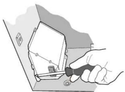
natural_image
Illustration of a hand using a screwdriver to adjust or install a component, with no visible text or symbols.
natural_image
Diagram of a mechanical assembly with a tool and component, no visible text or symbols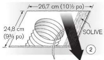
text_image
26,7 cm (10½ pa) 24,8 cm (9¾ pa) SOLIVE ②
6
text_image
Is better.natural_image
Technical line drawing of a mechanical or electrical component with wires and connectors (no text or symbols)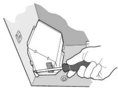
natural_image
Illustration of a hand using a tool to adjust or install a device into a box (no text or symbols visible)8
text_image
Diagram showing a hand holding a handheld device with directional arrows and labels indicating 'p', 'o', and 'F'9
Raccordez un conduit rond de 10 cm (4 po).
text_image
Diagram showing a hand holding a device with numbered arrows indicating motion or sequence, labeled 1, 2, and 3.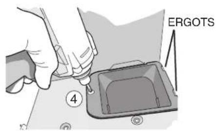
text_image
ERGOTS ④natural_image
Illustration of a hand using a screwdriver to adjust or install a mechanical component (no text or symbols visible)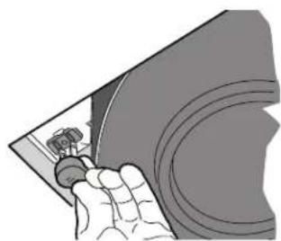
natural_image
Illustration of a hand holding a small object over a curved surface (no text or symbols visible)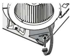
natural_image
Technical diagram of a mechanical device with gear and cable (no text or symbols)natural_image
Technical line drawing of a sewing machine needle stitching a grille (no text or symbols)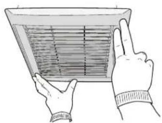
natural_image
Illustration of two hands holding a rectangular fan or vent with internal grid lines (no text or symbols)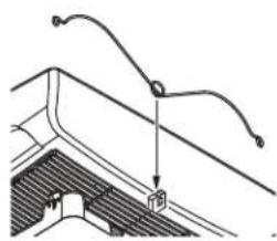
natural_image
Technical line drawing of a roof structure with curved and straight lines indicating components (no text or symbols)natural_image
Diagram of a mechanical device with a wheel and tool, showing internal components (no text or symbols)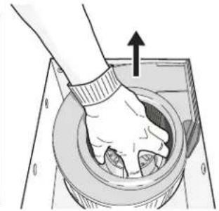
natural_image
Illustration of a hand pressing down on a circular mechanical component with an upward arrow (no text or symbols)2
natural_image
Illustration of hands installing or adjusting a small electronic device with an upward arrow (no text or symbols)3
natural_image
Technical line drawing of a mechanical housing or enclosure with mounting brackets and internal components (no text or symbols)natural_image
Technical diagram of a mechanical component with no visible text or symbolsnatural_image
Diagram of a mechanical assembly with arrows indicating motion or force direction (no text or symbols)8
natural_image
Technical line drawing of a mechanical or electrical component assembly (no text or symbols visible)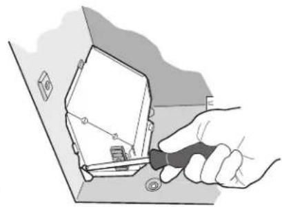
natural_image
Illustration of a hand using a tool to adjust or install an electrical component (no text or symbols visible)9
natural_image
Diagram of a mechanical assembly with a component inside a housing, no visible text or symbols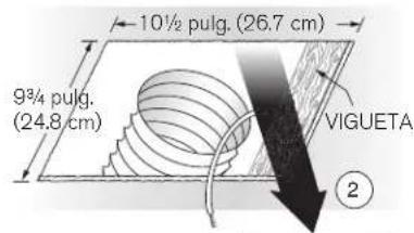
text_image
10½ pulg. (26.7 cm) 9¾ pulg. (24.8 cm) VIGUETA ②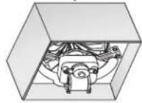
6
natural_image
Hand inserting a component into a 3D box with arrows indicating rotation (no text or symbols)natural_image
Technical diagram of a computer setup with cables and connectors (no text or labels)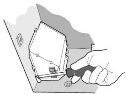
natural_image
Illustration of a hand using a tool to adjust or install a component on a surface (no text or symbols visible)8
text_image
Diagram showing a hand holding a handheld device with directional arrows indicating movement or force vectors around it, labeled with letters p, o, and 11.9
text_image
Diagram showing a hand holding a device with numbered arrows indicating motion or sequence, labeled 1, 2, and 3.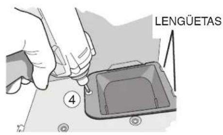
text_image
LENGÜETAS ④natural_image
Illustration of a hand using a screwdriver to adjust or install a mechanical component (no text or symbols visible)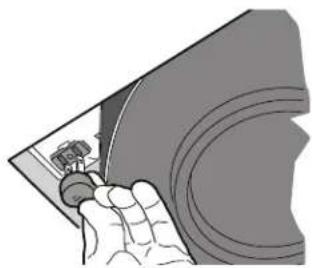
natural_image
Illustration of a hand holding a small object over a curved surface (no text or symbols visible)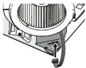
natural_image
Technical diagram of a mechanical device with internal components and cable (no text or symbols)Ventilador Serie Flex™ SOLAMENTE
11
Instale la rejilla.
natural_image
Technical line drawing of a sewing machine needle stitching a grille (no text or symbols)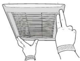
natural_image
Illustration of two hands holding a large air vent with grating (no text or symbols)