
WEF 15-150 Quick - Sander METABO - Free user manual and instructions
Find the device manual for free WEF 15-150 Quick METABO in PDF.

| Product type | Angle grinder (flat head angle grinder) |
| Brand | METABO |
| Model | WEF 15-150 Quick |
| Max. working tool diameter | 150 mm |
| Max. no-load speed | 8500 rpm (estimated) |
| Variable speed | Yes, adjustment wheel (11) |
| Power input | 1500 W (estimated) |
| Voltage / Frequency | 230 V ~ 50/60 Hz |
| Weight (without cable) | Approx. 2.5 kg (estimated) |
| Spindle thread | M14 (typical) |
| Spindle length | 22 mm (typical) |
| Protection class | II (double insulation) |
| Functions | Grinding, sanding with abrasive paper, wire brushing, cutting off |
| Safety | Adjustable protective guard, restart safety, electronic safety shutdown |
| Additional handle | Yes, with vibration damping option |
| Cleaning | Regularly clean the ventilation slots and dust filter |
| Maintenance | Use original Metabo accessories; repairs by an electrician |
| Recommended accessories | Cutting guard, handle guard, dust filter, multi-position bracket |
Frequently Asked Questions - WEF 15-150 Quick METABO
User questions about WEF 15-150 Quick METABO
0 question about this device. Answer the ones you know or ask your own.
Ask a new question about this device
Download the instructions for your Sander in PDF format for free! Find your manual WEF 15-150 Quick - METABO and take your electronic device back in hand. On this page are published all the documents necessary for the use of your device. WEF 15-150 Quick by METABO.
USER MANUAL WEF 15-150 Quick METABO
natural_image
Three metal angle surgeers with visible brand logos (no text or symbols on the main image)
natural_image
Close-up of a black and white industrial power tool with a curved arrow indicating rotation (no text or symbols visible)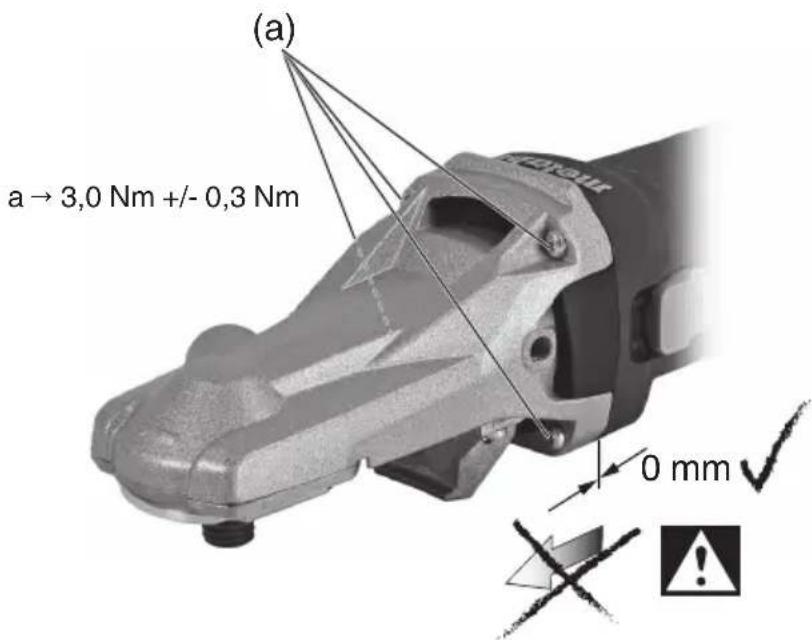

 | WEVF 10-125 Quick Inox *1) Serial Number: 13080.. | WEF 15-125 Quick *1) Serial Number: 13082.. | WEF 15-150 Quick *1) Serial Number: 13083.. | WEPF 15-150 Quick *1) Serial Number: 13084.. | WEPBF 15-150 Quick *1) Serial Number: 13085.. | |
| Electronic | - | VCTC TC | TC TC | |||
| ø | mm (in) | 125 (5) 125 | (5) 150 (6) 150 | (6) 150 (6) | ||
| t_max2; t_max3 | mm (in) | 5; 6 ( ^3/_16 ; ^1/_4 ) | ||||
| M / I - / mm (in) | M 14 / 19 ( ^3/_4 ) | |||||
| n min | ^-1 (rpm) | - 11000 | 9600 9600 9600 | |||
| n_v | min ^-1 (rpm) | 2000-7600 -- | ||||
| P_1 | W | 1000 1550 | 1550 1550 1550 | |||
| P_2 | W | 590 940 940 940 940 | ||||
| m kg (lbs) | 2,3 (5.1) 2,7 | (5.9) 2,7 (5.9) | 2,8 (6.2) 2,9 (6.4) | |||
| a_h,SG/K_h,SG | m/s ^2 | 4,4/1,5 6,0 | /1,5 6,8/1,5 6,8 | /1,5 6,8/1,5 | ||
| a_h,DS/K_h,DS | m/s ^2 | 2,5/1,5 3,6 | /1,5 3,4/1,5 3,4 | /1,5 3,4/1,5 | ||
| L_pA/K_pA | dB(A) | 91/3 | 91/3 | 91/3 | 91/3 | 89/3 |
| L_WA/K_WA | dB(A) | 102/3 | 102/3 | 102/3 | 102/3 | 100/3 |

*2) 2014/30/EU, 2006/42/EC, 2011/65/EU
*3) EN 60745-1:2009+A11:2010, EN 60745-2-3:2011+A2:2013+A11:2014+A12:2014

2016-02-10, Volker Siegle
Original Instructions
1. Declaration of Conformity
We, being solely responsible: Hereby declare that these flat head angle grinders, identified by type and serial number *1), meet all relevant requirements of directives *2) and standards *3). Technical documents for *4) - see page 4.
2. Specified Use
The flat head angle grinders, when fitted with original Metabo accessories, are suitable for grinding, sanding, cut-off grinding and wire brushing metal, concrete, stone and similar materials without the use of water.
The user bears sole responsibility for any damage caused by inappropriate use.
Generally accepted accident prevention regulations and the enclosed safety information must be observed.
3. General Safety Instructions

For your own protection and for the protection of your power tool, pay attention to all parts of the text that are marked with this symbol!

WARNING – Reading the operating instructions will reduce the risk of injury.

WARNING Read all safety warnings and instructions. Failure to follow all safety
warnings and instructions may result in electric shock, fire and/or serious injury.
Keep all safety instructions and information for future reference.
Pass on your power tool only together with these documents.
4. Special Safety Instructions
4.1 General Safety Recommendations for Grinding, Sanding, Wire Brushing or Cut-Off Grinding:
Use
a) This power tool is intended to function as a grinder, sander, wire brush or cut-off tool. Read all safety warnings, instructions, illustrations and specifications provided with this power tool. Failure to follow all instructions listed below may result in electric shock, fire and/or serious injury.
b) Operations such as polishing are not recommended to be performed with this power tool. Operations for which the power tool was not designed may create a hazard and cause personal injury.
c) Do not use accessories which are not specifically designed and recommended by the
tool manufacturer. Just because the accessory can be attached to your power tool, it does not assure safe operation.
d) The rated speed of the accessory must be at least equal to the maximum speed marked on the power tool. Grinding accessories running faster than their rated speed can break and fly apart.
e) The outside diameter and the thickness of your accessory must be within the capacity rating of your power tool. Incorrectly sized accessories cannot be adequately guarded or controlled.
f) Threaded mounting of accessories must match the grinder spindle thread. For accessories mounted by flanges, the arbour hole of the accessory must fit the locating diameter of the flange. Accessories that do not match the mounting hardware of the power tool will run out of balance, vibrate excessively and may cause loss of control.
g) Do not use a damaged accessory. Before each use inspect the accessory such as grinding wheels for chips and cracks, backing pad for cracks, tear or excess wear, wire brush for loose or cracked wires. If power tool or accessory is dropped, inspect for damage or install an undamaged accessory. After inspecting and installing an accessory, position yourself and bystanders away from the plane of the rotating accessory and run the power tool at maximum no-load speed for one minute. Damaged accessories will normally break apart during this test time.
h) Wear personal protective equipment. Depending on application, use face shield, safety goggles or safety glasses. As appropriate, wear dust mask, hearing protectors, gloves and workshop apron capable of stopping small abrasive or workpiece fragments. The eye protection must be capable of stopping flying debris generated by various operations. The dust mask or respirator must be capable of filtrating particles generated by your operation. Prolonged exposure to high intensity noise may cause hearing loss.
i) Keep bystanders a safe distance away from work area. Anyone entering the work area must wear personal protective equipment. Fragments of workpiece or of a broken accessory may fly away and cause injury beyond immediate area of operation.
j) Hold power tool by insulated gripping surfaces only, when performing an operation where the cutting accessory may contact hidden wiring or its own cord. Cutting accessory contacting a "live" wire may make exposed metal parts of the power tool "live" and shock the operator.
k) Position the cord clear of the spinning accessory. If you lose control, the cord may be cut or snagged and your hand or arm may be pulled into the spinning accessory.
ENGLISHen
I) Never lay the power tool down until the accessory has come to a complete stop. The spinning accessory may grab the surface and pull the power tool out of your control.
m) Do not run the power tool while carrying it at your side. Accidental contact with the spinning accessory could snag your clothing, pulling the accessory into your body.
n) Regularly clean the power tool's air vents.
The motor's fan will draw the dust inside the housing and excessive accumulation of powdered metal may cause electrical hazards.
o) Do not operate the power tool near flammable materials. Sparks could ignite these materials.
p) Do not use accessories that require liquid coolants. Using water or other liquid coolants may result in electrocution or shock.
4.2 Kickback and Related Warnings
Kickback is a sudden reaction to a pinched or snagged grinding wheel, backing pad, brush or any other accessory. Pinching or snagging causes rapid stalling of the rotating accessory. This causes the uncontrolled power tool to be forced in the direction opposite of the accessory's rotation at the point of the binding.
For example, if a grinding wheel is snagged or pinched by the workpiece, the edge of the wheel that is entering into the pinch point can dig into the surface of the material causing the wheel to climb out or kick out. The grinding wheel may either jump toward or away from the operator, depending on direction of the disc's movement at the point of pinching. Grinding wheels may also break under these conditions.
Kickback is the result of power tool misuse and/or incorrect operating procedures or conditions It can be prevented if suitable precautionary measures are taken as described below.
a) Maintain a firm grip on the power tool and position your body and arm to allow you to resist kickback forces. Always use auxiliary handle, if provided, for maximum control over kickback or torque reaction during start-up.
The operator can control torque reactions or kickback forces, if proper precautions are taken.
b) Never place your hand near the rotating accessory. Accessory may kickback over your hand.
c) Do not position your body in the area where the power tool will move if kickback occurs. Kickback
will propel the tool in direction opposite to the grinding wheel's movement at the point of snagging.
d) Use special care when working corners, sharp edges etc. Avoid bouncing and snagging the accessory. Corners, sharp edges or bouncing have a tendency to snag the rotating accessory and cause loss of control or kickback. and cause loss of control or kickback.
e) Do not attach a saw chain woodcarving blade or toothed saw blade. Such blades create frequent kickback and loss of control.
4.3 Safety Warnings Specific for Grinding and Cut-Off Grinding:
a) Use only wheel types that are recommended for your power tool and the specific guard designed for the selected wheel. Wheels for which the power tool was not designed cannot be adequately guarded and are unsafe.
b) The grinding surface of the centre depressed wheels must be mounted below the plane of the guard lip. An improperly mounted grinding wheel that projects through the plane of the guard lip cannot be adequately protected.
c) The guard must be securely attached to the power tool and positioned for maximum safety, so the least amount of wheel is exposed towards the operator. The guard helps to protect operator from broken wheel fragments and accidental contact with wheel and sparks which could ignite clothing.
d) Grinding media must be used only for recommended applications.
For example: Do not grind with the side of a cutting disc. Cutting discs are intended for peripheral grinding. Side forces applied to these wheels may cause them to shatter.
e) Always use undamaged wheel flanges that are of correct size and shape for your selected grinding wheel. Proper wheel flanges support the grinding wheel thus reducing the possibility of grinding wheel breakage. Flanges for cutting discs may be different from grinding wheel flanges.
f) Do not use worn down grinding wheels from larger power tools. Grinding wheels intended for larger power tools are not suitable for the higher speed of a smaller tool and may break.
4.4 Additional Safety Warnings Specific for Cut-Off Grinding:
a) Do not “jam” the cutting disc or apply excessive pressure. Do not attempt to make an excessive depth of cut. Overstressing the cutting disc increases the loading and susceptibility to twisting or binding of the disc in the cut and the possibility of kickback or disc breakage.
b) Do not position your body in line with and behind the rotating cutting disc. When the cutting disc, at the point of operation, is moving away from your body, the possible kickback may propel the spinning disc and the power tool directly at you.
c) If the cutting disc is binding or when interrupting a cut for any reason, switch off the power tool and hold the power tool motionless until the disc comes to a complete stop. Never attempt to remove the cutting disc from the cut while the disc is in motion otherwise kickback may occur. Investigate and take corrective action to eliminate the cause of disc binding.
d) Do not restart the cutting operation in the workpiece. Let the cutting disc reach full speed
and carefully re-enter the cut. The wheel may bind, walk up or kickback if the power tool is restarted in the workpiece.
e) Support panels or any oversized workpiece to minimize the risk of cutting disc pinching and kickback. Large workpieces tend to sag under their own weight. Supports must be placed under the workpiece near the line of cut and near the edge of the workpiece on both sides of the wheel.
f) Use extra caution when making "pocket cuts" into existing walls or other blind areas. The protruding cutting disc may cut gas or water pipes, electrical wiring or objects that can cause kickback.
4.5 Safety Warnings Specific for Sanding Operations:
a) Do not use excessively oversized sanding disc paper. Follow manufacturers recommendations, when selecting sanding paper. Larger sanding paper extending beyond the sanding pad presents a laceration hazard and may cause snagging, tearing of the disc or kickback.
4.6 Safety Warnings Specific for Wire Brushing Operations:
a) Be aware that wire bristles are thrown by the brush even during ordinary operation. Do not overstress the wires by applying excessive load to the brush. The wire bristles can easily penetrate light clothing and/or skin.
b) If the use of a guard is recommended for wire brushing, do not allow any interference of the wire wheel or brush with the guard. Wire wheel or brush may expand in diameter due to work load and centrifugal forces.
4.7 Additional Safety Instructions:

WARNING – Always wear protective goggles.
Use elastic cushioning layers if they have been supplied with the grinding media and if required.
Observe the specifications of the tool or accessory manufacturer! Protect the discs from grease or impacts!
Grinding wheels must be stored and handled with care in accordance with the manufacturer's instructions.
Never use cutting discs for roughing work! Do not apply pressure to the side of the cutting discs.
The workpiece must lay flat and be secured against slipping, e.g. using clamps. Large workpieces must be sufficiently supported.
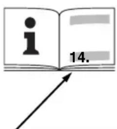
If accessories with threaded inserts are used, the end of the spindle may not touch the base of the hole on the grinding tool. Make sure that the thread in the accessory is long enough to accommodate the full length of the spindle. The thread in the accessory must match the thread on the spindle. See page 4 and chapter 14. Technical Specifications for more information on the spindle length and thread.
Use of a fixed extractor system is recommended. Always install an RCD with a maximum trip current of 30 mA upstream. If the angle grinder is shut down via the RCD, it must be checked and cleaned. See chapter 9. Cleaning.
Damaged, eccentric or vibrating tools must not be used.
Avoid damage to gas or water pipes, electrical cables and load-bearing walls (static).
Pull the plug out of the socket before making any adjustments, converting or servicing the machine.
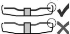
A damaged or cracked side handle must be replaced. Never operate a machine with a defective side handle.
A damaged or cracked safety guard must be replaced. Never operate a machine with a defective safety guard.
Secure small workpieces. For example, clamp in a vice.
This power tool is not suitable for polishing work. Improper use of the machine will void the warranty! The motor may overheat and damage the electric power tool. We recommend using our angle polisher for polishing work.
The accessory may not be fastened with a two-hole nut for safety reasons. Only use the (tool-free) clamping nut (2).
Reducing dust exposure:
Some of the particles generated using this power tool may contain substances known to cause cancer, allergic reactions, respiratory diseases, birth defects or other reproductive harm. Some of these substances include: Lead (in paint containing lead), mineral dust (from bricks, concrete etc.), additives used for wood treatment (chromate, wood preservatives), some wood types (such as oak or beech dust), metals, asbestos. The risk from exposure to such substances will depend on how long the user or nearby persons are being exposed.
Do not let particles enter the body.
Do the following to reduce exposure to these substances: Ensure good ventilation of the workplace and wear appropriate protective equipment, such as respirators able to filter microscopically small particles.
Observe the relevant guidelines for your material, staff, application and place of application (e.g. occupational health and safety regulations, disposal).
Collect the generated particles at the source, avoid deposits in the surrounding area.
Use suitable accessories for special work (see chapter 11.), thus less particles enter the environment in an uncontrolled manner.
Use a suitable extraction unit.
Reduce dust exposure with the following measures:
- Do not direct the escaping particles and the exhaust air stream at yourself or nearby persons or on dust deposits.
- Use an extraction unit and/or air purifiers.
ENGLISHen
- Ensure good ventilation of the workplace and keep it clean using a vacuum cleaner. Sweeping or blowing stirs up dust.
- Vacuum or wash protective clothing. Do not blow, beat or brush.
5. Overview
See page 2.
1 Clip to tighten/release the (tool-free) clamping nut manually *
2 Clamping nut (tool-free) *
3 Support flange
4 Spindle
5 Spindle locking button
6 Safety cover
7 Side handle/Additional handle with vibration damping *
8 Sliding on/off switch *
9 Handle
10 Electronic signal indicator
11 Speed adjustment wheel *
12 Switch-on lock*
13 Trigger switch *
14 Lever for safety guard attachment
* depending on equipment/not in scope of delivery
6. Commissioning

Before plugging in, check that the rated mains voltage and mains frequency, as stated on the plate match your power supply.

Always install an RCD with a maximum trip current of 30 mA upstream.
6.1 Attaching the additional handle

Always work with the additional handle (7) attached! Attach the additional handle on the right of the machine and secure.
6.2 Attach the safety guard

For safety reasons, always use the safety guard provided for the respective wheel! See chapter 11. Accessories!
Safety guard for grinding
Designed for work with roughing wheels, flap sanding pads, diamond cutting discs.
See illustration C on page 2.
- Place the safety guard (6) in the position indicated.
- Push the lever (14) and turn the safety guard until the closed section is facing the operator.
- Release lever and rotate guard until the lever latches.
- Make sure that the guard is placed securely: The lever must engage and you should not be able to turn the safety guard.
Use only accessories that are covered by at least 3.4 mm by the safety guard.
(Disassemble in reverse order.)
7. Attaching the grinding wheel

Prior to any conversion work: Pull the mains plug from the socket. The machine must be hed off and the spindle at a standstill.

For reasons of safety, attach the cut-off grinding guard before performing cut-off ing work (see Chapter 11. Accessories).
7.1 Locking the spindle

Press in the spindle locking button (5) only when the spindle is stationary.
- Press in the spindle locking button (5) and turn the spindle (4) by hand until the spindle locking button engages.
7.2 Placing the grinding wheel in position
See illustration B on page 2.
- Fit the support flange (3) on the spindle. The flange should not turn on the spindle when properly attached.
- Place the grinding wheel on the support flange (3). The grinding wheel must lay flat on the supporting flange.
7.3 Securing/releasing the (tool-free) clamping nut

Only tighten the (tool-free) clamping nut (2) by hand!

For the machine to operate, the clip (1) must always lie flat on the clamping nut (2).
To secure the (tool-free) clamping nut (2):

Use only accessories which fulfil the specifications. See Chapter 14. Technical).
- Lock the spindle (see chapter 7.1).
- Flip up the clip (1) on the clamping nut.
- Fit the clamping nut (2) on the spindle (4). See illustration A on page 2.
- Tighten the clamping nut on the clip (1) manually in a clockwise direction.
- Flip down the clip (1) again.
Release the (tool-free) clamping nut (2):
- Lock the spindle (see chapter 7.1).
- Flip up the clip (1) on the clamping nut.
- Unscrew the clamping nut (2), turning it anticlockwise manually.
Note: If the clamping nut (2) is very tightly secured, you can also use a 2-hole spanner to unscrew it.
8. Use
8.1 Adjusting the speed (depending on features)
Set the recommended speed at the thumbwheel (11). (small number = low speed; large number = high speed)
Cutting disc, roughing disc, cup wheel and diamond cutting disc: high speed
Brush: medium speed
Sanding plate: low to medium speed
Note: We recommend using our angle polisher for polishing work.
8.2 Switching On and Off

Always guide the machine with both hands.

Switch on first, then guide the accessory towards the workpiece.

The machine must not be allowed to draw in additional dust and shavings. When switching machine on and off, keep it away from dust deposits. After switching off the machine, only place own when the motor has come to a standstill.

Avoid inadvertent starts: always switch the tool off when the plug is removed from the s socket or if there has been a power cut.

In continuous operation, the machine continues running if it is forced out of your is. Therefore, always hold the machine with hands using the handles provided, stand rely and concentrate.
Machines with slide switch:
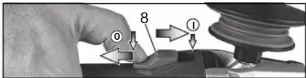
Switching on: Push the sliding switch (8) forward. For continuous activation, now tilt downwards until it engages.
Switching off: Press the rear end of the sliding switch (8) and release the sliding switch.
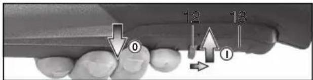
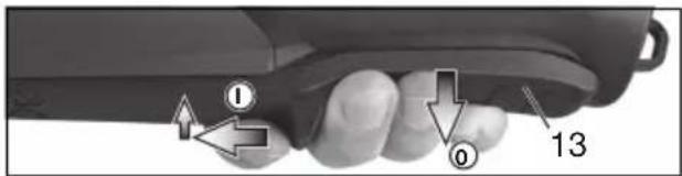
WEPF 15-150 Quick:
"Paddle switch" (with dead man's function):

Switching on: Slide the switch-on lock (12) in the direction of the arrow and press the trigger switch (13).
Switching off: Release the trigger switch (13).
WEPBF 15-150 Quick:
"Paddle switch" (with dead man's function):
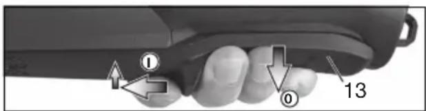
Switching on: Slide the trigger switch (13) in the direction of the arrow and press the trigger switch (13).
Switching off: Release the trigger switch (13).
8.3 Working Directions
Grinding and sanding operations:
Press down the machine evenly on the surface and move back and forth so that the surface of the workpiece does not become too hot.
Rough grinding: position the machine at an angle of 30^ - 40^ for the best working results.
Cut-off grinding:
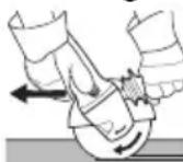
Always work against the run of the disc (see illustration). Otherwise there is the danger of the machine kicking back from the cut out of control. Guide the machine evenly at a speed
suitable for the material being processed. Do not tilt, apply excessive force or sway from side to side.
Wire brushing:
Press down the machine evenly.
8.4 Rotate gear housing
See illustration D on page 3.
- Disconnect the mains plug.
- Remove guard (6).
- Unscrew the 4 gear housing screws (a). CAUTION! Do not remove the gear housing!
- Turn the gear housing to the desired position without removing it.
- Screw in the 4 gear housing screws (a) in the available threads! Tightening torque = 3,0 Nm +/- 0,3 Nm.
9. Cleaning
It is possible that particles deposit inside the power tool during operation. This impairs the cooling of the power tool. Conductive build-up can impair the protective insulation of the power tool and cause electrical hazards.
The power tool should be cleaned regularly, often and thoroughly through all front and rear air vents using a vacuum cleaner or by blowing in dry air. Prior to this operation, separate the power tool from the power source and wear protective glasses and dust mask.
Regularly clean dust filter: remove and blow out with compressed air.
10. Troubleshooting
- Electronic safety shutdown The electronic signal display (10) flashes and the machine was automatically SWITCHED OFF. If the slew rate of the current is too high (for example, if the machine suddenly seizes or kickback occurs), the machine switches off. Switch machine off with switch. Switch it on again and continue to work as normal. Try to prevent the machine from seizing. See chapter 4.2.
Machines with VTC and TC electronics:

The electronic signal display (10) lights up and the load speed decreases. There is too much load on the machine! Run the machine in idling until the electronics signal indicator switches off.
Machines with VTC, TC and VC electronics:

The electronic signal display (10) flashes and the machine does not start. The restart protection is active. If the mains plug is
ENGLISHen
inserted with the machine switched on, or if the power supply is restored following an interruption, the machine does not start up. Switch the machine off and on again.
11. Accessories
Use only genuine Metabo accessories. See page 5.
Use only accessories which fulfil the requirements and specifications listed in these operating instructions.
A Safety guard for cut-off grinding
Designed for work with cutting disc and diamond cutting discs.
Install as described under "Safety guard for grinding" (chapter 6.2).
B Hand guard for sanding and wire brushing operations
Designed for work with support plates, sanding pads, wire brushes.
Install hand guard under the additional side-mounted handle.
C Dust filter
The fine mesh filter prevents coarse particles from entering the motor housing. Remove regularly and clean.
D Multiple position bar for side handle
Permits numerous handle positions.
See www.metabo.com or the catalogue for a complete range of accessories.
12. Repairs

Repairs to electrical tools must ONLY be carried out by qualified electricians!
If the connection lead is damaged, it must be replaced by a special connection lead.
Contact your local Metabo representative if you have Metabo power tools requiring repairs. See www.metabo.com for addresses.
You can download a list of spare parts from www.metabo.com.
13. Environmental Protection
The generated grinding dust may contain harmful substances. Do not dispose with household trash; dispose of properly at a collection point for hazardous waste.
Observe national regulations on environmentally compatible disposal and on the recycling of disused machines, packaging and accessories.

Only for EU countries: Never dispose of power tools in your household waste! In accordance with
European Directive 2002/96/EC relating to electrical and electronic waste and implementation of national law, used electrical tools must be collected separately and disposed of
in an environmentally friendly manner at recycling centres.
14. Technical Data
Explanatory notes on the specifications on page 3. Changes due to technological progress reserved.
∅ = max. diameter of the accessory
$$ \begin{array}{r l} {t _ {\max, 2}} & {= \max. \text { permitted thickness of clamping }} \ & {\quad \text { shank on accessory when using (tool - }} \ & {\quad \text { free) clamping nut (2) }} \end{array} $$
$$ \begin{array}{r l} t _ {\max, 3} & = \text { roughing disc / cutting disc: } \ & \quad \text { max. permitted thickness of accessory } \end{array} $$
$$ M \quad = \quad s \quad p \quad i \quad n $$
I = length of the grinding spindle
n^*=no-load speed (maximum speed)
n_V^*=no-load speed (adjustable)
$$ P _ {1} \quad = R a t e d i n p u t p o w e r $$
P_2 = Power output
m = Weight without mains cable
Measured values determined in conformity with EN 60745.
□ Machine in protection class II
\~ AC Power
* Machines with the designation WE... : Energy-rich, high-frequency interference can cause fluctuations in speed. The fluctuations disappear, however, as soon as the interference fades away.
The technical specifications quoted are subject to tolerances (in compliance with the relevant valid standards).
Emission values
These values make it possible to assess the emissions from the power tool and to compare different power tools. The actual load may be higher or lower depending on the operating conditions, the condition of the power tool or the accessories. Please allow for breaks and periods when the load is lower for assessment purposes. Arrange protective measures for the user e.g. organisational measures based on the adjusted estimates.
Vibration total value (vector sum of three directions) determined in accordance with EN 60745:
$$ \begin{array}{r l} a _ {h, S G} & = \text { Vibration emission value } \ & \text {(surface grinding)} \end{array} $$
$$ \begin{array}{r l} a _ {h, D S} & = \text { Vibration emission value } \ & \text {(sanding with sanding plate)} \end{array} $$
K_h,SG/DS = Uncertainty (vibration)
Typical A-effective perceived sound levels:
$$ L _ {p A} \quad = \text { sound - pressure level } $$
$$ L _ {W A} = \text { Acoustic power level } $$
K_pA, K_WA = Uncertainty
During operation the noise level can exceed 80 dB(A).
Wear ear protectors!
Notice originale
Voir page 2, figure C.
Voir page 2, figure B.
"Paddle-schakelaar" (met dodemansknop):
"Paddle-schakelaar" (met dodemansknop):
Tilkobling: Skub afbrydergrebet (13) i pilens retning, og tryk derefter på afbrydergrebet (13).
Frakobling: Slip afbrydergrebet (13).