
Albatros II - Chair Vermeiren - Free user manual and instructions
Find the device manual for free Albatros II Vermeiren in PDF.

| Product Type | Patient Lift |
| Brand | Vermeiren |
| Model | Albatros II |
| Intended Use | Transfer of seated patients between wheelchair, bed, bathroom |
| Maximum Load Capacity | 150 kg |
| Total Weight (with battery) | 50.60 kg |
| Total Length | 1115 mm |
| Total Width | 685 mm |
| Minimum Height (motor low) | 1380 mm |
| Maximum Height (motor high) | 1687 mm |
| Lifting Range | 637 mm |
| Chassis Spread | 467 - 769 mm |
| Turning Radius | 1160 mm |
| Power Supply | Battery 24 V DC, built-in charger 100-240 V AC |
| Battery Runtime | Approximately 40 lifts per charge |
| Lifting/Lowering Time | 28 seconds |
| Safety Devices | Emergency stop, manual emergency lowering, parking brakes |
| Materials | Steel frame with anti-corrosion coating |
| Cleaning | With mild detergent and damp cloth |
| Maintenance | Annual inspection by authorized dealer |
| Expected Lifespan | 8 years |
| Standards | CE compliant, IPX4/IPX5 protection classes |
| Included Accessories | Sling, leg rests, chest support, hand control, battery, built-in charger, straps |
Frequently Asked Questions - Albatros II Vermeiren
User questions about Albatros II Vermeiren
0 question about this device. Answer the ones you know or ask your own.
Ask a new question about this device
Download the instructions for your Chair in PDF format for free! Find your manual Albatros II - Vermeiren and take your electronic device back in hand. On this page are published all the documents necessary for the use of your device. Albatros II by Vermeiren.
USER MANUAL Albatros II Vermeiren
MANUEL D'UTILISATION
GEBRUIKSAANWIJZING
GEBRAUCHSANWEISUNG
natural_image
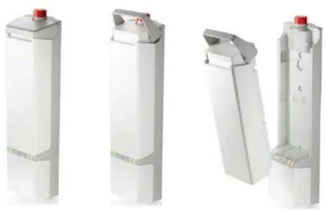
Modern medical mobility device with articulated limbs and a white seat, no visible text or symbols on the device body.EN
Instructions for specialist dealer
This instruction manual is part and parcel of the product and must accompany every product sold.
Version: C, 2022-10
FR
All rights reserved, including translation.
This page is intentionally left blank
Contents
Contents....1
Preface....2
1 Your product....3
2 Before use ....4
2.1 Intended Use 4
2.2 General safety instructions 4
3 Using the patient hoist ....5
3.1 Operating the lift 5
3.2 Slings 8
3.3 Battery and charging 11
3.4 Emergency 12
4 Installation and adjustment....13
4.1 Delivery....13
4.2 Assembly or dismantling 13
4.3 Changing the battery 20
5 Maintenance....21
5.1 Time of maintenance 21
5.2 Shipping and storage 22
5.3 Cleaning 22
5.4 Disinfection 22
5.5 Inspection 23
5.6 Expected lifespan 23
5.7 Reuse....23
5.8 End of use 23
6 Troubleshooting....24
7 Technical specifications....25
Preface
Congratulations! You are now owner of a Vermeiren patient hoist!
This product is made by qualified and committed personnel. It is designed and produced according to high quality standards, guarded by Vermeiren.
Thank you for your trust in the products of Vermeiren. To support you on the use of this patient hoist and its operating options, this manual is offered. Please read it carefully; it will help you to get familiar with the operation, capabilities and limitations of your product.
If you still have questions after reading this manual, do not hesitate to contact your specialist dealer. He/she will be glad to help you.
Important note
To ensure your safety and to prolong the lifetime of your product, please take good care of it and have it checked and serviced on a regular basis.
This manual reflects the latest product developments. Vermeiren has the right to implement changes to this type of product without any obligation to adapt or replace similar products previously delivered.
Pictures of the product are used to clarify the instructions in this manual. Details of the depicted product may deviate from your product.
Information available
On our website http://www.vermeiren.com/ you will always find the most recent version of the information in this manual. Please consult this website regularly for possible updates.
Visually impaired people can download the electronic version of this manual and have it read out by means of a text-to-speech software application.

This user manual
For user and specialist dealer

Service manual
For specialist dealer

EC declaration of conformity
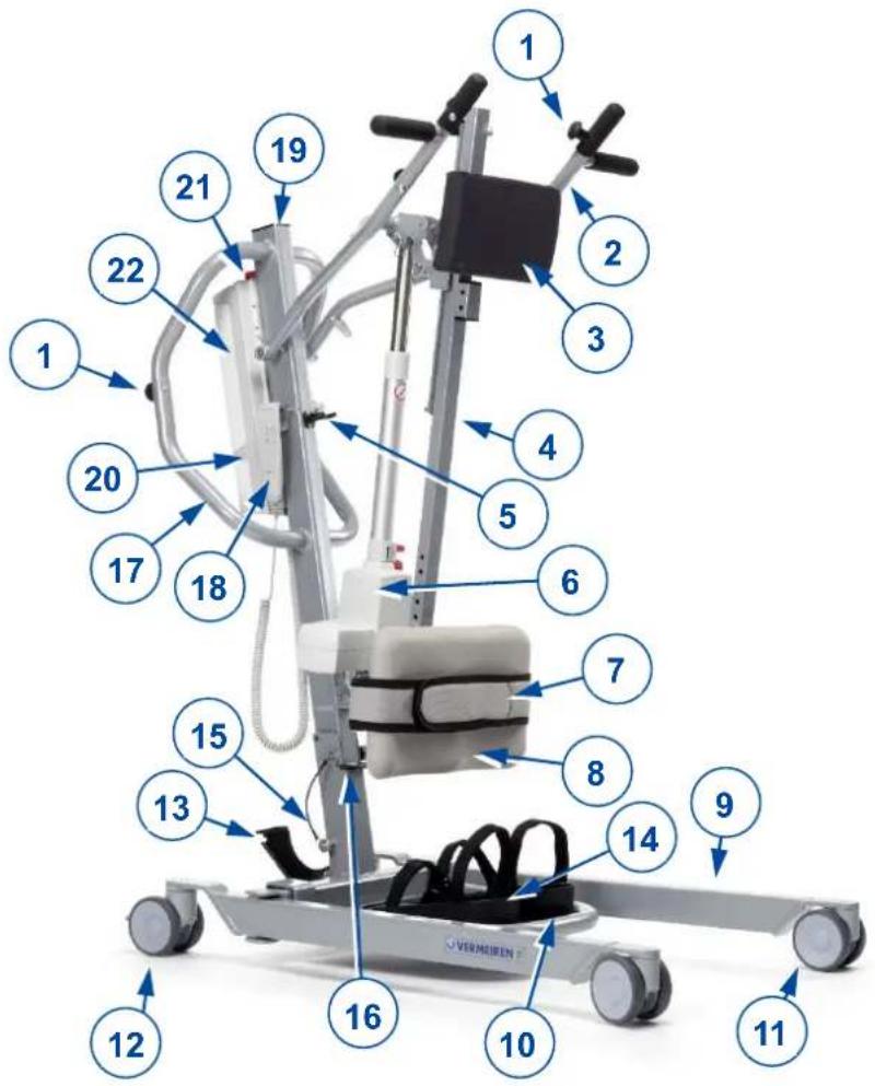
1 Your product
-
Buttons for mounting straps
-
Cantilever arm
-
Thorax cushion
-
Slide column
-
Transport holder for motor
-
Motor
-
Leg belt
-
Leg support
-
Chassis
-
Footplate
-
Caster
-
Caster with brake
-
Chassis expansion pedal
-
Footrests with velcro fastening
-
Safety spindle
-
Foldaway lock
-
Handle for pushing
-
Manual control
-
Pole
-
Control box
-
Emergency stop
-
Battery
2 Before use
2.1 Intended Use
In this paragraph a brief description of the intended use of your patient hoist is given. Additionally, relevant warnings are added to the instructions in the other paragraphs. In this way we would like to make you aware of the possible misuse that may appear.
- Indications and contraindications: This patient hoist is meant to be operated by an attendant to transfer sitting patients between e.g. wheelchairs, nursing beds and bathrooms. The patient hoist is designed and produced to be a transport/transfer aid for elderly persons or persons who suffer from paralysis, limb loss or defects, stiff or damaged joints, cardiovascular problems, cachexia, ... . When used accordingly, no contraindications are known.
• This patient hoist is suitable for indoor use. - This patient hoist is designed and produced solely to transport/transfer one (1) person with a maximum weight of 150 kg. It is not designed for transportation of goods or objects, nor for any use other than previously described.
- Only use accessories and spare parts approved by Vermeiren.
- Please read all technical details and limits of your patient hoist in chapter 7.
- The warranty on this product is based on normal use and maintenance as described in this manual. Damage to your product caused by improper use or lack of maintenance will cause the warranty to lapse.
2.2 General safety instructions
Risk of injuries and/or damage
Please read and follow the instructions in this manual. Otherwise you may get injured or your patient hoist may get damaged.
Keep the following general warnings in mind during use:
- The patient hoist must only be operated by qualified staff who have been instructed or trained in its specific application.
- Do not exceed the maximum load for the patient hoist. This will shut down the control box.
- In case of different user weights for patient hoist and slings, always observe the lowest user weight.
- An attendant needs to be present during the lifting operation.
- Be aware that some parts of the patient hoist may get very hot or cold due to ambient temperature, solar radiation or heating devices. Be careful when touching.
- The patient hoist has been tested for electromagnetic compatibility and complies with the standard. Nevertheless, sources of electromagnetic fields may influence the performance of the patient hoist, such as the fields of mobile phones, power generators or high-power energy sources. On the other hand, the electronics of the patient hoist can affect other electronic appliances too.
- Only use the patient hoist on flat surfaces where all castors touch the ground and where there is sufficient contact to operate the patient hoist safely. Do not take obstacles with the patient hoist while transferring a patient.
- Do not use the patient hoist in wet or humid environments.
- Alterations or substitutions should not be made to the patient hoist securement points or to structural and frame parts or components without consulting the manufacturer.
- Make sure that your hands, clothes, belts, buckles or jewellery don't get caught by wheels or other moving parts during use.
- Be careful with sources of ignition such as lit cigarettes as they may set the sling alight.
In case a serious incident has occurred involving your product, notify Vermeiren or your specialist dealer as well as the competent authority in your country.
3 Using the patient hoist
3.1 Operating the lift

CAUTION
Risk of injuries and/or damage
- When using the lift, make sure that there is sufficient room around and above it, as the adjustment movements could otherwise lead to damage or injury.
• Always be aware of the lifting arm to avoid injury. - Only slings that have been designed and approved for the patients must be used (see usage instructions for the various slings). Use of any other slings is at your own risk.
- Only use the handles to push/pull the patient hoist, no other components.
Please observe the technical information according to which the patient hoist may be operated. The patient hoist must only be operated by authorised staff who have been trained in its use and operation.
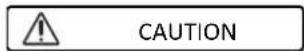
3.1.1 Altering the chassis width
natural_image
Mechanical assembly diagram showing a cart with wheels and directional arrows indicating motion (no text or symbols)To get the lift around a wheelchair or other seating furniture, or to increase the stability of the lift in the standing position, the separation of the chassis legs can be increased.
Stand behind the assembled lift and take hold of the handles for pushing the patient hoist (on the left and right, next to the control box). Press the lever at the bottom of the chassis (left or right) down with your foot, and the separation of the legs of the chassis can be increased or decreased.
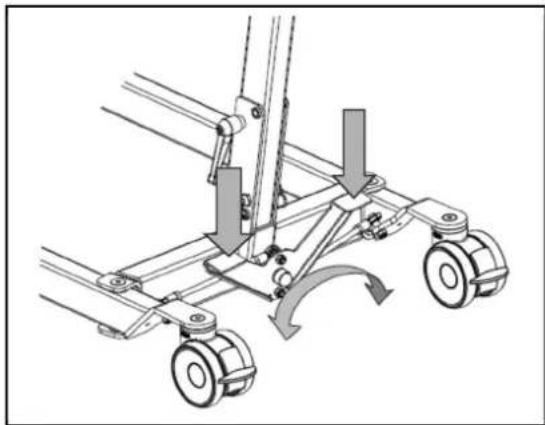
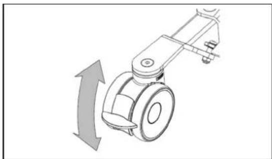
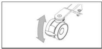
3.1.2 Parking brakes
natural_image
Mechanical device with a curved arrow indicating rotational motion (no text or symbols)Secure the two casters at the back of the chassis by pressing the caster brake plates down gently to their end stops with the tip of your foot. To release the brake, push the brake plate gently back up again with the front of your foot until the casters are free.
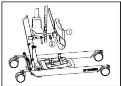
3.1.3 Footplate
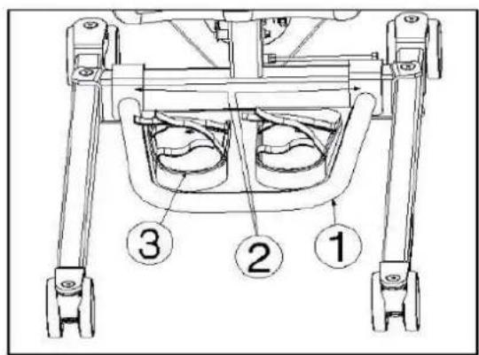
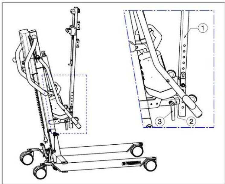
The footplate ① can be mounted or removed with the hooks ② to/from the chassis of the patient hoist. If it is required for a greater stabilization of your feet you can use the special footrests ③ with velcro straps for stabilization.
3.1.4 Leg support

CAUTION
Risk of injuries
- Do not drop the leg support on the patient when adjusting.
The leg support ① can be mounted on the bar of the patient hoist ② with the safety pin ③.
The leg support is meant to keep the legs of the patient in the correct position and to support the legs of the patient while standing up.
The leg supports can be adjusted in depth and 9 different heights.
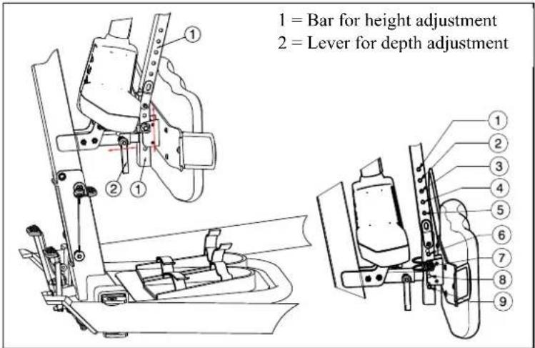
| Height from footplate to top of leg support | Position |
| 690 mm | Hole 1 |
| 665 mm Hole 2 | |
| 640 mm | Hole 3 |
| Do not use Hole 4 | |
| Do not use Hole 5 | |
| 495 mm | Hole 6 |
| 470 mm Hole 7 | |
| 445 mm Hole 8 | |
| 420 mm | Hole 9 |
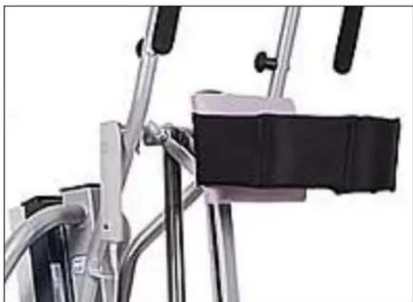
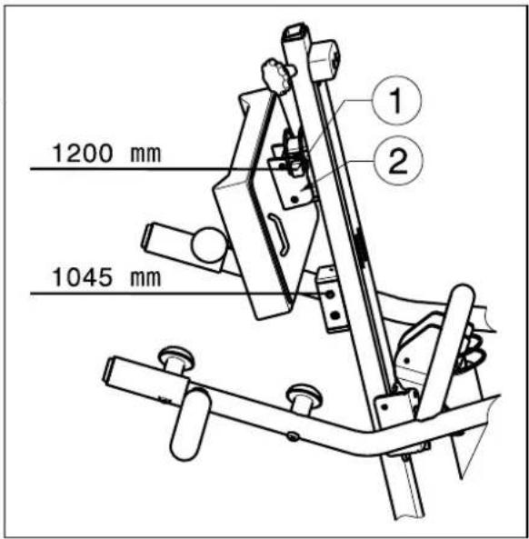
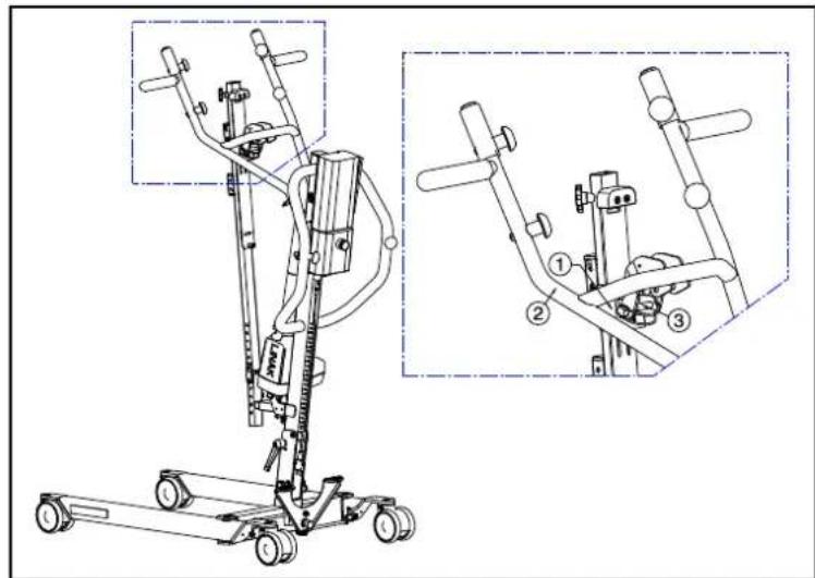
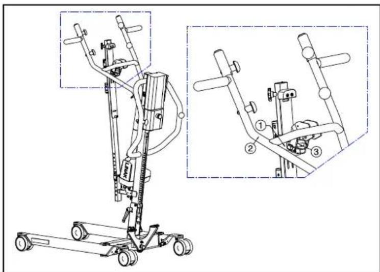
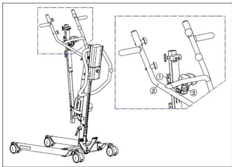
3.1.5 Thorax support
natural_image
Close-up of a bicycle support frame with metal frame and black seat (no visible text or symbols)To stabilize and support your thorax, the lift is equipped with thorax pillow and velcro belts to stabilize.
The thorax support can be adjusted in 2 different positions 1045 mm, 1200 mm. These positions are measured from the footplate until the top of the thorax support.
- Remove the safety pin ①.
-
Adjust the thorax support in the desired position. The position from attachment plate ② shall be like shown in figure.
-
Mount the safety pin ① securely.
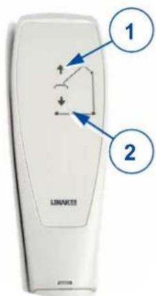
3.1.6 Raising and lowering the cantilever arm
The manual control allows the cantilever arm to be adjusted smoothly to any point.
① = Raise the cantilever arm
② = Lower the cantilever arm
When using the lift function until the end of the hoist motor, the limit switch is activated by electronics (security function). Use the lifting function only in the middle of the adjustment range.
3.1.7 Moving the patient hoist

CAUTION
Risk of injuries
- Be careful passing through restricted passages (e.g. doors).
- Stand behind the patient hoist and grasp the handles (left and right, next to the control box) with both hands.
- Make sure that both back caster brakes have been released.
- Push the patient hoist slowly into the desired position.
When it is not loaded, we advise you to pull the patient hoist backwards, which makes it easier to get round any obstacles (door frames, corners of rooms or furniture).
3.1.8 Turn the patient hoist around his axle

CAUTION
Risk of injuries
- Be careful there are no people or objects in the swing range of the patient hoist.
-
Turn the patient hoist carefully and slowly around his axle, so that the patient cannot swing out.
-
Open the legs of the patient hoist to give more stability.
- Activate the brakes.
-
Place the patient in the patient hoist with the appropriate sling. (refer to sling manual for instructions of placing the patient in the hoist).
-
Lift the patient from the ground, chair, bed, ...
- Loosen both brakes of the rear wheels.
- Stand behind the patient hoist and grasp the handgrips (left and right next to the control box) with both hands.
- Now turn the patient hoist carefully, slowly around on the same place. Be careful you do not touch any objects with the legs of the patient hoist.
- When you are turned in the good position, you can lift the patient down.
3.2 Slings

CAUTION
Risk of injuries
- Only use appropriate slings for the patients.
- Do not use damaged slings.
- Read the full slings manual first.
- Only use compatible slings approved by Vermeiren.
3.2.1 Attachment points on patient lift
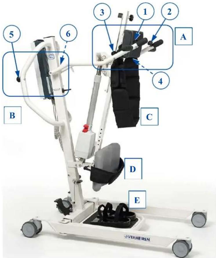
A. Attachments thorax belt
B. Attachments waist belt
C. Thorax support
D. Leg support
E. Feet support
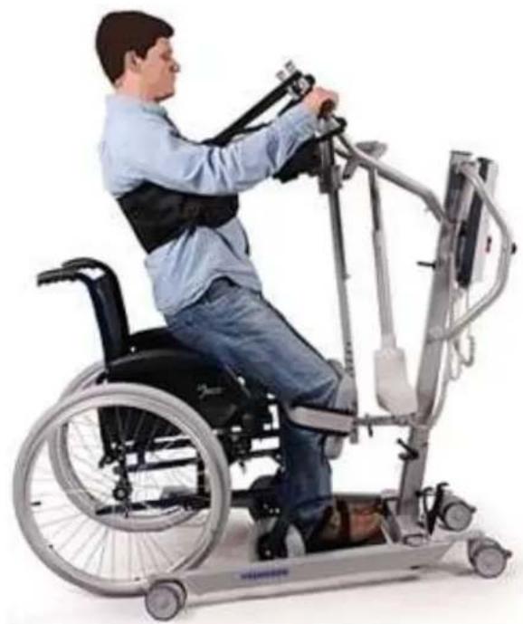
3.2.2 Instructions for lifting patient
Phase I – Preparation. In this phase, the patient should stay on the footplate and put his feet in the special footrests with the velcro fastening. Then stabilize your feet and legs under your knees by using the velcro belt on the foot- and leg support. Make sure that the feet and legs are firmly touching the pillow from the foot- and leg support. Fasten the thorax belt with the four straps to the patient hoist.
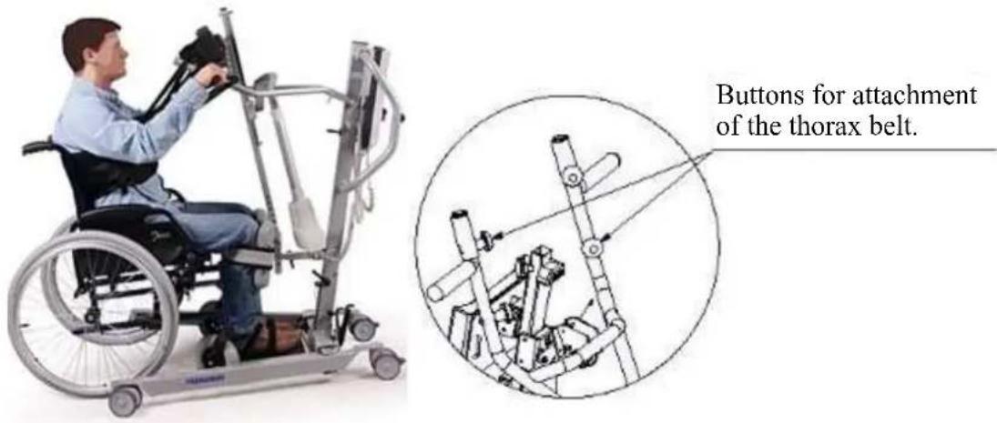
Phase II- Lifting. Use the manual control slowly to lift the patient up. The patient must hold the handgrips during lifting.
natural_image
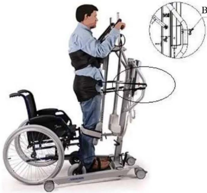
Person in a wheelchair using a stationary exercise machine (no visible text or symbols)Phase III – Stabilization. In the last step after lifting to the vertical position, the patient is stabilized by thorax belts. Thorax belts are mounted on both sides of the thorax support. Afterwards you can remove the vest. To complete stabilization you should use the waist belt which stabilizes the hip and trunk of the cross section. In this way, the patient is fully protected in four support points: feet, knees, hips and thorax.
natural_image
Person in wheelchair using a mobility exercise machine, with inset diagram showing structural components (no text or symbols)Buttons for waist belt attachment
View properly how the patient is stabilized.

natural_image
Person using a mobility exercise machine (no visible text or symbols)3.3 Battery and charging
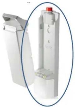
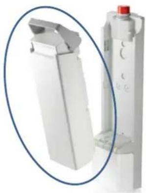
3.3.1 Battery
natural_image
Close-up of a white industrial component with a red knob, shown in an oval detail (no text or symbols visible)The battery is above the control box and is replaceable with an integrated clip system.
| Primary voltage 24 VDC | |
| Ambient temperature +5°C to +40°C | |
| Ambient storage temperature -10° to +40°C | |
| Relative storage humidity | max. 80 |
| Conformity | tested i |
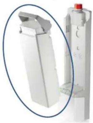
3.3.2 Control box + included battery charger
natural_image
Close-up of a white plastic mechanical component with a red knob, shown in an oval frame (no text or symbols visible)The control box is designed with a red emergency stop and an internal battery charger.
| Primary voltage | 100 - 240 VAC / 50/60 Hz |
| Secondary voltage (charging voltage) | 24 VDC, max. 250 VA |
| Secondary current (charging current) | max. 10 A |
| Safeguards | Protected against reverse polarisation, electrical surge and extreme temperature |
| Ambient temperature | +5°C to +40°C |
| Ambient storage temperature | -10° to +40°C |
| Relative storage humidity | max. 80% (non-condensing tested in accordance with IEC 60601-1 |
| Conformity |
We reserve the right to introduce technical changes.
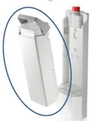
3.3.3 External charger (OPTIONAL)
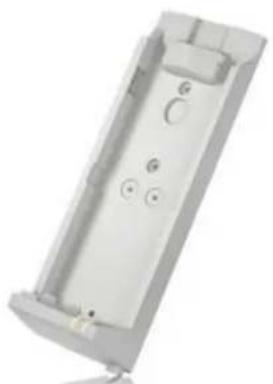
natural_image
Exterior view of a rectangular electronic device casing with mounting holes and internal compartments (no text or symbols visible)The external charger shall be mounted on the wall. It is possible to charge the spare battery (optional) with this external charger and you have no waiting time to use the patient hoist when charging the batteries.
| Primary voltage | 100 - 240 VAC / 50/60 Hz |
| Charging current | max. 650 mA |
| Ambient temperature | +5°C to +40°C |
| Ambient storage temperature | -10° to +40°C |
| Relative storage humidity | max. 80% (non-condensing) |
3.3.4 Charging the batteries
Use only the control box with included battery charger on the Albatros II or the external charger meant to be mounted on the wall.
We recommend that you should regularly recharge the batteries in order to ensure that the hoist remains usable and to extend the lifespan of the batteries. The control box will give a warning sound to tell you when the battery charge is low.
First use
First, insert the supply cable with the connector side into the appropriate connector on the control box. The plug side of the supply cable must be insert in the socket outlet. The loading time is about 24 hours.
Recharging
⚠ WARNING: Risk of injury – Do not use the lift when the supply cable is connected in the socket outlet.
When the battery is running low, half of the green LED will blink and a single beep can be heard when the hoist is activated.
If the LED is blinking and a continuous beep can be heard, there are only two cycles left on the battery.
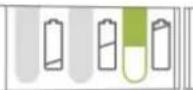
When the batteries are recharging, half of the LED will light green. The battery is fully charged once the LED is fully green.
After the recharging process is completed, you should always remove the mains plug from the socket first and then remove the connector plug from the control box.
Do not use the lift while it is being recharged!
If the batteries are not used for a significant period, they discharge slowly by themselves (deep discharge). It then becomes impossible to recharge them. You should therefore recharge the batteries at least once a month even if they are not being used.
3.4 Emergency
In cases for emergency the emergency stop and the function for lowering in an emergency must be used.
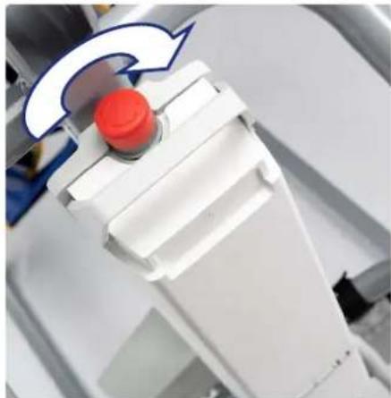
3.4.1 Emergency stop
In emergencies, and during assembly and disassembly, the emergency stop is activated by pressing the red button on the control box.
Push on the button and turn in the direction of the arrows. If the button is fully pressed to the back turn back in the opposite direction of the arrows.
The emergency stop is deactivated by turning the red button in the direction of the arrows.
natural_image
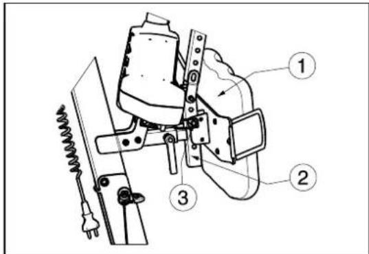
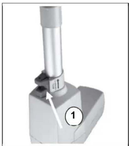
Close-up of a white robotic arm with a red button and blue arrow indicator (no text or symbols)3.4.2 Emergency lowering
WARNING: Risk of injury – Adjust the manual emergency lowering for the weight of the patient.
Emergency lowering if the power fails or the batteries are empty can be done using the red pull button ① at the lower end of the motor. This emergency lowering is factory-set for a patient weight of 50 kg.
Standard calibration: 2500N, 15 mm/s to lower the patiënt.
Please note that the manual emergency lowering is only possible when the patient is sitting in the patient hoist.
natural_image
Mechanical component with a cylindrical shaft and base, labeled with number 1 (no text or symbols on the object itself)4 Installation and adjustment
The patient hoist is delivered fully assembled by your specialist dealer.
The instructions in this chapter are for the specialist dealer.
To find a service facility or specialist dealer near you, contact the nearest Vermeiren facility.
WARNING: Risk of unsafe limitations - Use only the limitations described in this manual.
4.1 Delivery
The Vermeiren Albatros II patient hoist shall be delivered with:
- chassis including 4 casters (2 with brakes)
- pole, including handles for pushing
- cantilever arm with attachment for sling
• control box (+ included battery charger) - battery
- manual control
- motor
- instruction manual
- foot plate + footrests with velcro fastening
- leg support
- thorax support
Before use check if everything is included and that no products are damaged (example by transport, ...).
Please note that the basic configuration may vary from one European country to another. Please contact the specialist dealer in your country for more information.
4.2 Assembly or dismantling
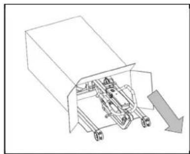
4.2.1 Unpacking
WARNING: Risk of injury - After unpacking and before further assembly, always first confirm that the emergency stop (the red pushbutton on the control box) is pressed in.
The patient hoist packaging has been selected to provide the best possible protection during transport.
natural_image
Technical line drawing of a mechanical assembly with no visible text or symbols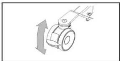
natural_image
Mechanical component diagram showing a rotating arm with directional arrow (no text or symbols)-
Take the patient hoist out of the box and check that all the items have been delivered and that the individual parts do not have any visible defects. If there is any damage, please contact your sales office.
-
Before assembly, put on the caster brakes to make sure that the lift cannot be moved unintentionally. Push the caster brake plate down gently to its end stop with the front of your foot. To release the brake, push the brake plate gently back up again with the front of your foot until the caster is free.
4.2.2 Assembly
⚠ WARNING: Risk of clamping - Take care that no body parts and wires get trapped, crushed or cut during assembly.
natural_image
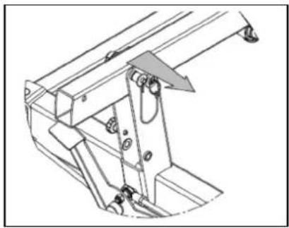
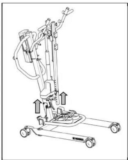
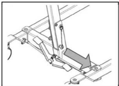
Technical line drawing of a mechanical assembly with no visible text or symbols- Remove the safety spindle (locking pin) from the bottom end of the pole by gently pressing the button at the head of the spindle. The safety spindle can now be removed easily.
natural_image
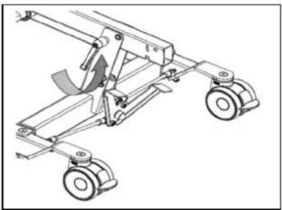
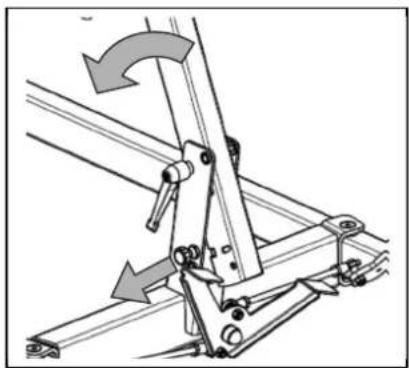
Technical line drawing of a mechanical suspension system with wheels and a curved component (no text or symbols)- Undo the transport lock (wing screw) gently and the pole can now be raised.
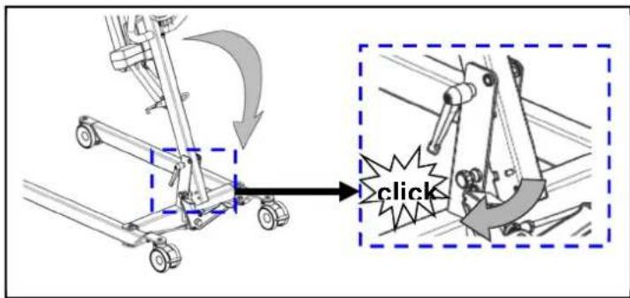
2.a The standing position safety (traction screw) clicks audibly into place once the pole is put in its final position.
natural_image
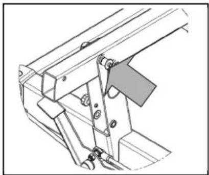
Technical line drawing of a mechanical assembly with wheels and brackets (no text or symbols)- ⚠ WARNING: Risk of injury - Make sure that the safety spindle is correctly inserted.
Fix the pole in place by pushing the safety spindle at the end of the pole in with the pushbutton depressed until its other end clearly protrudes. Release the pushbutton on the safety spindle and check that it cannot be pulled out.
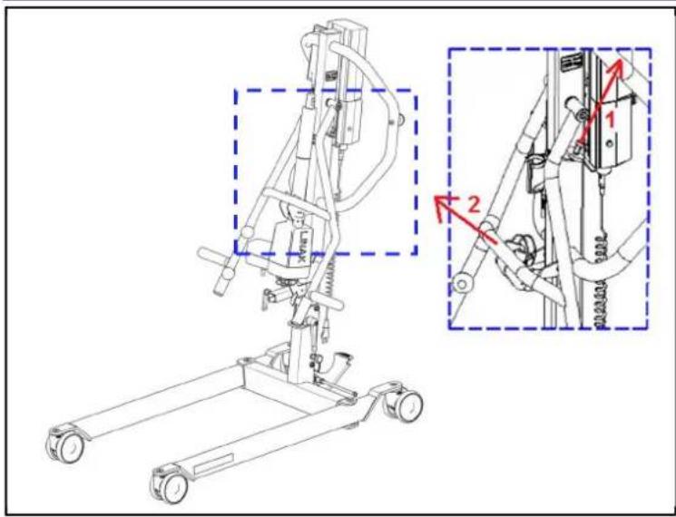
-
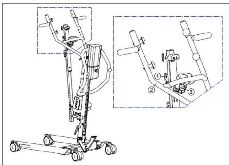
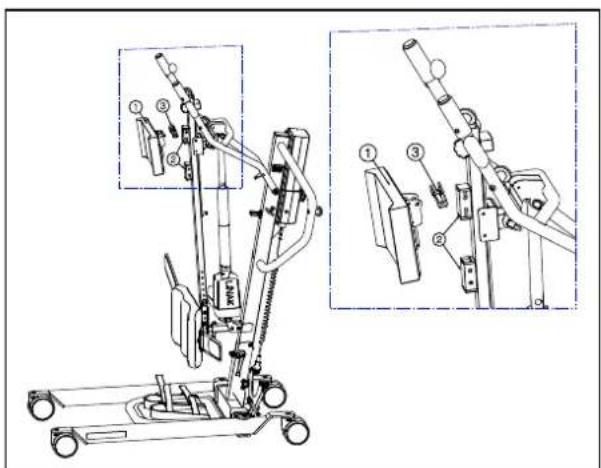
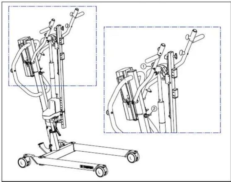
Remove the cantilever arm from the top end of the pole ②. This is possible by pulling on the pen ①.
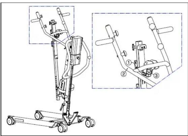
-
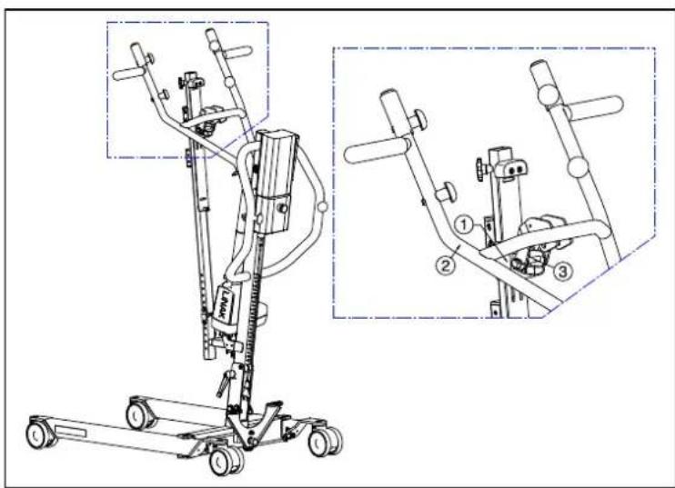
Mount the slide column ① with the foot support attachment ② in the tube of the patient hoist frame. Retighten the lever ③.
-
Attach the slide and slide holder ① to the cantilever arm ② with the locking pin ③.
natural_image
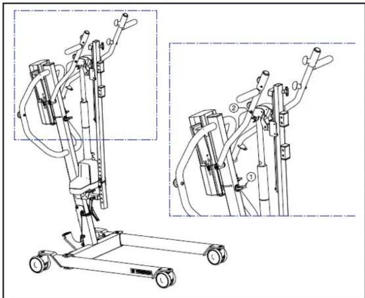
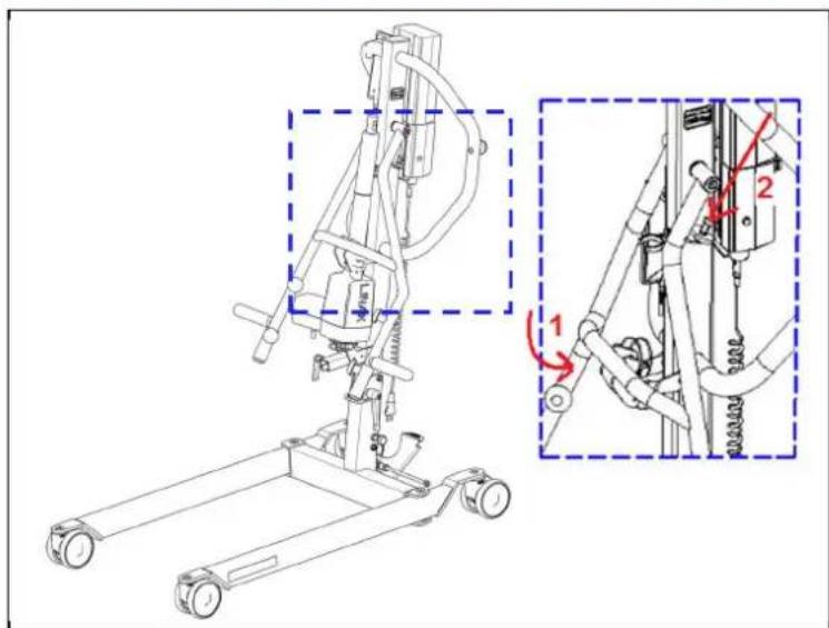
Technical line drawing of a mobile exercise lift with two views (dual and zoomed-in) showing internal components and shafts (no text or labels)-
Pull the actuator gently out the black clip ①.
-
Attach the actuator on the cantilever arm by the locking pin ②. Take care that the actuator is positioned very well between the cantilever arm.
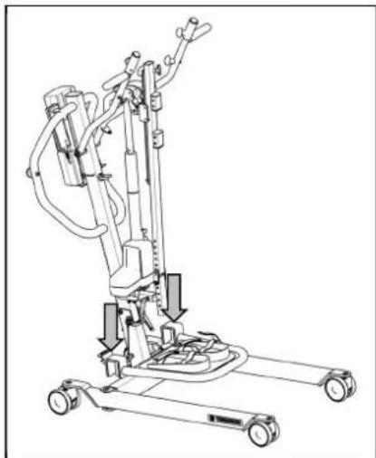
natural_image
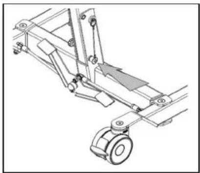
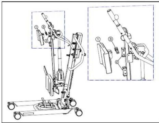
Technical line drawing of a mechanical lift or lift support system with no visible text or symbols- Attach the footplate with the hooks to the chassis of the patient hoist.
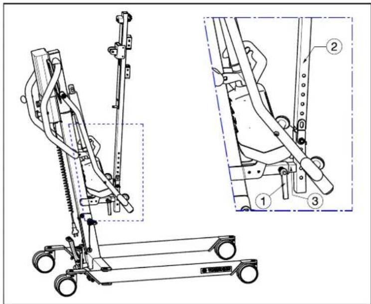
- Attach the leg support ① with the locking pin ②. Position the leg support ① to the desired height and depth.
- Mount the thorax support ① to the slide column ② with the locking pin ③ in a comfortable height for every patient.
4.2.3 Dismantling
WARNING: Risk of clamping - Take care that no body parts and wires get trapped, crushed or cut during dismantling.
WARNING: Risk of injury - Check the emergency stop (red pushbutton on the control box) is activated, to avoid unintentional adjustment movements.
natural_image
Mechanical component diagram showing a rotating arm with directional arrow (no text or symbols)- Secure the two casters at the back of the chassis by pressing the caster brake plates down gently to their end stops with the tip of your foot. To release the brake, push the brake plate gently back up again with the front of your foot until the casters are free.
- Remove the thorax support ① from the slide column ② with the locking pin ③.
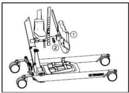
- Remove the leg support ① by the locking pin ②.
natural_image
Line drawing of a mobile vacuum cleaner with attached-mounted wheels and control panel (no text or symbols)- Remove the footplate from the chassis of the patient hoist.
natural_image
Technical line drawing of a mobile exercise stand with two views (dual and zoomed-in) showing mechanical components and wiring (no text or symbols present)-
Dismantle the actuator (motor) from the cantilever arm by removing the locking pin ①.
-
Move the actuator to the bottom position and place the actuator in the black clip ②.
- Remove the slide and slide holder ① from the cantilver arm ② with the locking pin ③.
- Loosen the lever ①. Remove the slide column ② and foot support attachment ③ out the tube of the patient hoist frame.
- Move the cantilever arm to the bottom position ①. Fasten the pen on the top end of the pole in the hole of the cantilever arm ②.
natural_image
Mechanical assembly diagram showing a lever mechanism with no visible text or symbols- Remove the safety spindle (locking pin) from the bottom end of the pole by gently pressing the button at the head of the spindle. The safety spindle can now be removed easily.
natural_image
Mechanical linkage diagram showing a lever mechanism with no text or symbols- ⚠ WARNING: Risk of injury - Once the pole is unlocked, its own weight can cause considerable downward forces to be exerted.
Pull out the standing position safety (traction screw) until the pole is released and can be tilted. The pole can now be tilted forwards.
Tip the pole as far as possible forward.
natural_image
Technical line drawing of a mechanical assembly with no visible text or symbols- ⚠ WARNING: Risk of injury - Make sure that the safety spindle is correctly inserted.
Fix the pole in place by pushing the safety spindle at the end of the pole in with the pushbutton depressed until its other end clearly protrudes. Release the pushbutton on the safety spindle and check that it cannot be pulled out again.
4.3 Changing the battery
• We shall decline all liability for damage caused by the use of improper battery.
- Do not use the battery at temperatures below +5°C or above +50°C (the ideal is +20°C).
• If the battery is opened, all liability of the manufacturer shall be voided as well as any claim.
natural_image
Four white industrial cylindrical components with red caps, shown from different angles (no text or symbols visible)The battery of the patient hoist can be swapped by an integrated clip system.
To swap the battery pull on the integrated clip system. The plate will be lifted and the battery can be taken off the holder (control box).
5 Maintenance
5.1 Time of maintenance

CAUTION
Risk of injuries and damage
Repairs and replacements may only be undertaken by trained persons and only genuine replacement parts of Vermeiren should be used (see the maintenance manual).
i The last page of this manual contains a registration form for the specialist dealer to record each service.
The service frequency depends on the frequency and intensity of use. Contact your dealer to agree to a common timetable for inspection/maintenance/repair.
For the maintenance manual, refer to the Vermeiren website: www.vermeiren.com.
Before each use
Inspect the following points:
- All parts: present and undamaged or unworn.
• All parts: clean, see §5.3. - Condition of frame parts: no deformation, instability, weakness or loose connections.
- Brakes: no visible damage and/or dirt.
- Control box, manual control, battery charger, relevant cables: no damage such as wires that have become frayed, broken or exposed. Check that the electrical adjustment of the cantilever arm is working properly, using the manual control.
- Battery status: charge the battery when necessary, see §3.3.
Approx. every 8 weeks
Depending on the frequency of use, check the following:
• Lubrication of the joints of the cantilever arm
• Condition of the casters
- Whether there is any visible damage to the casing of the control box, battery, battery charger and the manual controls
• Whether the cables are fit for use
- Recharge the battery
Approx. every 6 months or for every new user
Depending on the frequency of use check the following:
- Cleanliness
- General condition
- Casters are working
If the resistance to rotation is too great, clean the casters. If this is insufficient, please consult your dealer.
Yearly or more often
Have the patient hoist inspected and serviced by your specialist dealer, at least once a year, or more often. The minimum maintenance frequency depends on use and should therefore be commonly agreed upon with your specialist dealer.
5.2 Shipping and storage
- Shipping and storage should happen according to the technical specifications in §7. Make sure that the patient hoist is stored dry.
- Prevent cables from being crushed or bent with kinks.
- Disconnect the patient hoist from the socket.
- Provide sufficient covering or packaging to protect the patient hoist against rust and foreign bodies. (e.g. salt water, sea air, sand, dust).
- Store all removed parts together in one place (or mark them if necessary) to avoid mixing up with other products when re-assembling (e.g. the charger).
- Make sure no objects are stored on or against the patient hoist and its components to prevent damage.
5.3 Cleaning
CAUTION
Risk of damage by moisture
- Never use a hose or high-pressure cleaner.
- Use a mild commercial detergent to remove stubborn dirt.
• Stains can be removed by using a sponge or a soft brush. - Do not use strong cleaning liquids like solvents, nor use hard brushes.
5.3.1 Plastic parts
Clean plastic parts of your patient hoist with commercial plastic cleaners. Read the specific product information and only use a soft brush or soft sponge.
5.3.2 Coating
The patient hoist consists of steel components. The high quality of the surface layer guarantees optimal protection against corrosion. If the outer coat is damaged by scratching or in some other way, get your specialist dealer to repair the affected surface.
When cleaning, only use warm water and normal household detergents and soft brushes and cloths. Ensure that no wetness gets into the tubes.
5.3.3 Electronics casing
WARNING: Risk of injury - The emergency stop must be activated before maintenance work, so that no unintentional adjustment movements can be made.
Wipe the control box, motor casing and manual controls down with a cloth moistened by a few drops of a commercial domestic cleaner. Do not use abrasives or sharp-edged polishing equipment like a metal scrubber or brush, as these can scratch the surface of the manual control and destroy its water repelling property.
Regularly check the plug connectors for corrosion or damage, as these could affect the functional integrity of the electronics.
The manufacturer will not accept liability for damages caused by insufficient maintenance.
5.4 Disinfection
All parts of the patient hoist can be treated by scrubbing with a commercial disinfectant. Follow the instructions on the disinfectant.
Washing instructions for slings can be found in the slings manual and on the label of each sling.
5.5 Inspection
In principle we recommend one inspection every year, and a minimum of one before usage is resumed. All of the following checks must be performed and documented by authorized persons:
- Check the cabling (in particular for crushing, wear, cuts, visible parts of the insulation of the inner wires, visible metal wire cores, kinks, bulges, colour changes of the outer sleeve, brittle spots, and safe positioning so that mechanical effects such as being cut or crushed are not probable).
- Visual inspection of the frame parts to check for plastic deformation and/or wear and tear (frame, motor suspension, cantilever arm, spreader bar).
- Visually check for damage to the paintwork (danger of corrosion).
• Visual inspection of all casings for damage: screws must be tight.
- Verify the amount of grease on the metal joints of movable parts
- Visually check all plastic parts for cracks and brittle spots
- Review the charger, control box + included charger residual discharge current (A) based on VDE 0702
- Review the charger, control box + included charger insulation resistance (MO) based on VDF 0702
- Functional test of the cantilever arm (lubrication of the joint parts, range of adjustability, deformation, wear and tear)
- Check the functioning of the hoist drives (during a test drive → noises, speed, free running, etc.), if necessary: Measure the performance, first with no load and then with the nominal load ("SWL"), to investigate the wear and tear of the motors by comparing the values for the electric current against the values when it was delivered.
• Functional test of the emergency stop
• Functional test of the emergency lowering
• Completeness of the delivery condition, instruction manual available?
Checking measurements may only be carried out by skilled persons trained on the patient hoist at least and at least under the supervision of an electrician who knows the checking instruments and processes. Only an electrician can release the patient hoist for use after making the measurements and carrying out the servicing.
The service must only be signed off in the maintenance plan if a minimum of all the above-mentioned aspects have been checked.
5.6 Expected lifespan
The average lifespan of the patient hoist is 8 years. Depending on the frequency of use, storage, maintenance, servicing and cleaning, the lifespan of the patient hoist will increase or decrease.
5.7 Reuse
Before each reuse, have the patient hoist disinfected, inspected and serviced according to the instructions in this chapter.
5.8 End of use
At end of life, you need to dispose of the patient hoist according to the local environmental legislation. The best way to do so, is to disassemble the patient hoist to facilitate the transport of recyclable parts.
6 Troubleshooting
Table 1: Troubleshooting
| Problem Cause of | problem Problem solving | |
| Noisy sound of the moving parts (example: cantilever arm). | Lubrication is necessary. Lubricate | the moving parts.(Do not lubricate the actuator!) |
| Actuator makes an unusual sound. | The actuator is damaged. Replace | the actuator or contact your specialist dealer. |
| Patient hoist does not lift anymore. | 1. Electric actuator is damaged.2. The user weight is too high (system status LED blinks, two beeps can be heard).3. Manual control or actuator are not connected.4. Battery not connected or not connected properly to control box.5. Battery too low.6. Emergency stop is activated (system status LED is on). | 1. Replace the actuator.2. Use a patient hoist with higher maximum user weight.3. Check connections. If necessary connect manual control or actuator.4. Check battery is installed or the connection of the battery.5. Charge the batteries or replace.6. Deactivate the emergency stop. |
| Lowering the patient in case of emergency does not work. | There is required a minimum weight load to lower the patient. | If the patient weight is too low pull down slightly on the cantilever arms or adjust the lowering speed. |
| Battery cannot be charged | 1. Batteries not fitted correctly to control box.2. Mains cable defect.3. Batteries are defected.4. Control box with included charger is defected5. Battery charger is defected | 1. Check batteries are connected to the control box.2. Change mains cable.3. Replace battery.4. Replace control box with included charger.5. Replace new battery charger. |
7 Technical specifications
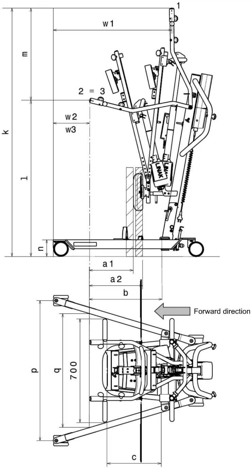
Table 2: Technical specifications
| Brand | Vermeiren |
| Type | Patient hoist |
| Model | Albatros II |
| Description | Measurement in drawing | Dimensions |
| Lowest CAP position* l 1060 mm | ||
| Highest CAP position* k 1687 mm | ||
| Lifting range (range of heights) m 637 mm | ||
| Leg length 1000 mm | ||
| Total length 1115 mm | ||
| Total width | 685 mm | |
| Total height | 1380 mm (actuator lowest position)1687 mm (actuator highest position) | |
| Folded / Dismantled length | 1115 mm (not foldable) | |
| Folded / Dismantled width | 685 mm (not foldable) | |
| Folded / Dismantled height | 500 mm | |
| Minimum leg separation | r | 467 mm |
| Maximum leg separation | q 769 mm | |
| Leg height / Frame height | n 117 mm | |
| Overall width (closed), external dimension | 584 mm | |
| Overall width (opened), castors forwards | P | 945 mm |
| Min. distance between wall / CSP* (minimum height) | w3 (=w2) | 285 mm |
| Min. distance between wall / CSP* (maximum reach) | w2 (=w3) | 285 mm |
| Min. distance between wall / CSP* (maximum height) | w1 | 870 mm |
| Turning circle | 1160 mm | |
| Total weight | 50,60 kg | |
| Weight of chassis + motor + control box | 34,50 kg | |
| Weight of battery | 2,90 kg | |
| Weight of footplate | 5,10 kg | |
| Weight of thorax support | 1,40 kg | |
| Weight of leg support | 3,00 kg | |
| Weight attachment of leg support and lifting column | 3,60 kg | |
| Maximum load | 150 kg | |
| Free height, minimum | 57 mm | |
| Maximum reach at 600 mm with leg support | a1 300 mm | |
| Maximum reach at 600 mm without legsupport | a2 | 360 mm |
| Maximum reach from support | b 495 mm | |
| Reach from support at separation 700 mm | c | 375 mm |
| Brand | Vermeiren |
| Type | Patient hoist |
| Model | Albatros II |
| Description | Measurement in drawing | Dimensions |
| Power outlet | 24V --- max. 250 VA | |
| Supply voltage 120-240V ~ max. 37-53 VA | ||
| Maximum current drawn max. 350 mA | ||
| Operating temperature +5 to +40°C | ||
| Relative humidity 20% to 80% at 30°C, non-condensing | ||
| Noise level | < 50 dB(A) | |
| Air pressure | 700 to 1060 hPa | |
| Control box | Linak CAL40 | |
| Battery | Linak BAL40 | |
| Manual control Linak HB3X0L0 | ||
| Motor | Linak LA34 (7500N) | |
| Control box protection class | IPX4 | |
| Battery protection class | IPX5 | |
| Manual control protection class | IPX5 | |
| Motor protection class | IP54 | |
| Insulation class | II - Type B | |
| Operational performance | approx. 40 lifts per charge | |
| Lifting/Lowering speed | 28 sec. | |
| Periodic operation | max. 10%, or 2 min. continuous operation/18 min. pauses | |
| Battery capacity | 2.9 Ah | |
| Emergency stop | Yes | |
| Manual lowering in emergency | Yes | |
| Electrical lowering in emergency | No | |
| We reserve the right to introduce technical changes. Measurement tolerance ± 15 mm / 1,5 kg / 1,5° | ||
1 = Highest position, 2 = Maximum reach, 3 = Lowest position
* CSP = Central suspension point
Table des matières
natural_image
Mechanical assembly diagram showing a cart with wheels and a curved arrow indicating motion (no text or symbols)natural_image
Mechanical assembly diagram showing a rotating wheel with directional arrow indicating rotation (no text or symbols)natural_image
Close-up of a bicycle seatbelt mechanism with metal frame and black belt (no visible text or symbols)= Soulever la poience
= Abaisser la potence
natural_image
Person in a wheelchair using a stationary exercise machine (no visible text or symbols)natural_image
Person in wheelchair using a mobility exercise machine, with inset diagram showing mechanical components (no text or symbols)natural_image
Person using a transsorption machine with articulated joints and control panels (no visible text or symbols)natural_image
Close-up of a white industrial component with a red knob, shown in an oval detail (no text or symbols visible)natural_image
Close-up of a white industrial machine component with a red button and control panel, shown in an oval view (no text or symbols visible)natural_image
Exterior view of a white rectangular electronic device casing with mounting holes and internal components (no text or symbols visible)natural_image
Close-up of a white industrial control panel with a red button and blue arrow indicator (no text or symbols)natural_image
Mechanical component with a cylindrical shaft and base, labeled with number 1 and an arrow indicating direction (no text or symbols on the object itself)natural_image
Technical illustration of a mechanical device with internal components and directional arrows indicating motion (no text or symbols)natural_image
Technical line drawing of a mechanical assembly with no visible text or symbolsnatural_image
Technical line drawing of a mechanical suspension system with wheels and a curved arrow indicating motion (no text or symbols)natural_image
Technical line drawing of a mechanical assembly with levers and wheels (no text or symbols)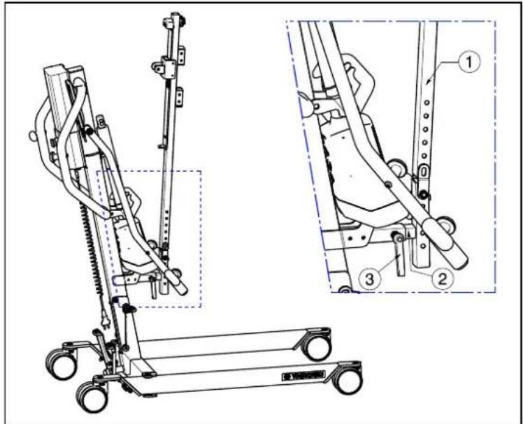
natural_image
Technical line drawing of a mobile exercise lift with two views (dashed and solid) showing internal components and shafts (no text or labels)natural_image
Technical line drawing of a mechanical lift or support system with wheels and guide rails (no text or symbols)natural_image
Mechanical component diagram showing a rotating arm with directional arrow (no text or symbols)natural_image
Line drawing of a manual vacuum cleaner with attached control panel and wheels (no text or symbols)natural_image
Technical line drawing of a mobile exercise stand with two views (dual and zoomed-in) showing mechanical components and wiring (no text or symbols present)natural_image
Technical line drawing of a mechanical lift with three views (no text or symbols)natural_image
Mechanical assembly diagram showing a lever mechanism with a gray arrow indicating motion direction (no text or symbols present)natural_image
Mechanical linkage diagram showing a lever mechanism with no text or symbolsnatural_image
Technical line drawing of a mechanical bracket assembly (no text or symbols)natural_image
Four white industrial cylindrical components with red caps and mounting brackets, shown from different angles (no text or symbols visible)natural_image
Mechanical assembly diagram showing a cart with wheels and a curved arrow indicating motion (no text or symbols)natural_image
Mechanical assembly diagram showing a rotating component with an upward arrow indicating rotational motion (no text or symbols)natural_image
Close-up of a bicycle seatbelt mechanism with metal frame and black belt (no visible text or symbols)② = Hefarm neerlaten
natural_image
Person in a wheelchair using an exercise machine (no visible text or symbols)natural_image
Person in a wheelchair using a stationary exercise machine, with an inset diagram showing mechanical components (no text or symbols present)Knoppen om de taillegordel te bevestigen
natural_image
Person using a mobility exercise machine (no visible text or symbols)3.3 Batterij en laden
3.3.1 Batterij
natural_image
Close-up of a white industrial control unit with a red knob and blue circular outline (no visible text or symbols)natural_image
Close-up of a white industrial cutting tool with a red knob, shown in an oval view (no text or symbols visible)natural_image
Exterior view of a white rectangular electronic device casing with mounting holes and a handle (no text or symbols visible)natural_image
Close-up of a white robotic arm with a red knob and blue circular arrow indicator (no text or symbols)natural_image
Mechanical component with a cylindrical shaft and base, labeled with number 1 (no text or symbols on the object itself)4 Montage en afstelling
natural_image
Technical line drawing of a mechanical device with internal components and directional arrows indicating motion (no text or symbols)natural_image
Technical line drawing of a mechanical assembly with no visible text or symbolsnatural_image
Mechanical assembly diagram showing a linkage mechanism with wheels and a curved arrow indicating motion (no text or symbols)natural_image
Technical line drawing of a mechanical support system with wheels and brackets (no text or symbols)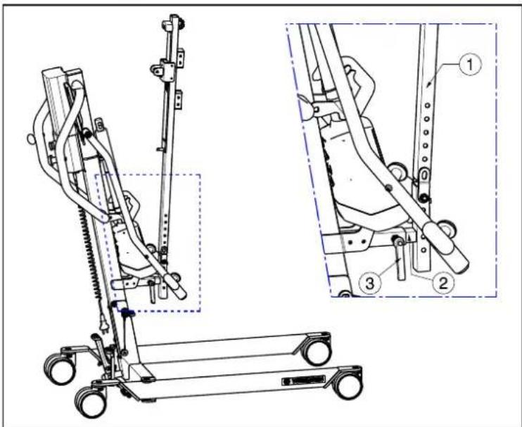
natural_image
Technical line drawing of a mobile exercise stand with two views (dashed and solid) showing internal components and shafts (no text or labels)natural_image
Technical line drawing of a mobile crane lift with attached platform and wheels (no text or symbols)natural_image
Diagram of a mechanical device with a rotating wheel and directional arrow (no text or symbols)natural_image
Line drawing of a vacuum cleaner with attached mechanical components and directional arrows indicating motion (no text or symbols)natural_image
Technical line drawing of a mobile exercise stand with two views (top and side), no text or symbols present.natural_image
Mechanical assembly diagram showing a lever mechanism with a gray arrow indicating motion direction (no text or symbols present)natural_image
Mechanical linkage diagram showing a lever mechanism with no text or symbolsnatural_image
Technical line drawing of a mechanical bracket assembly (no text or symbols)natural_image
Three white industrial cylindrical components with red connectors, shown from different angles (no text or symbols visible)natural_image
Mechanical assembly diagram showing a cart with wheels and a curved arrow indicating motion (no text or symbols)natural_image
Mechanical linkage diagram showing a wheel and shaft with an upward arrow indicating rotational motion (no text or symbols)3.1.4 Beinstütze

WARNUNG
Verletzungsgefahr
natural_image
Close-up of a bicycle support frame with metal frame and black seat (no visible text or symbols)natural_image
Person in a wheelchair using a stationary exercise machine (no visible text or symbols)natural_image
Person in wheelchair using a stationary exercise machine, with inset diagram showing mechanical components (no text or symbols)natural_image
Person using a mobility exercise machine (no visible text or symbols)
natural_image
Close-up of a white industrial device with a red knob, shown in an oval view (no text or symbols visible)natural_image
Exterior view of a white industrial cutting tool with a red knob and mounting bracket (no text or symbols visible)natural_image
Exterior view of a white plastic enclosure with internal compartments and mounting holes (no text or symbols)natural_image
Close-up of a white robotic arm with a red button and blue circular arrow, no visible text or symbolsnatural_image
Mechanical component with a cylindrical shaft and base, labeled with number 1 and an arrow pointing to it (no text or symbols on the object itself)DE
natural_image
Technical line drawing of a mechanical device with internal components and directional arrows indicating motion (no text or symbols)natural_image
Technical line drawing of a mechanical assembly with no visible text or symbolsnatural_image
Technical line drawing of a mechanical linkage system with wheels and a curved arrow indicating motion (no text or symbols)natural_image
Technical line drawing of a mechanical assembly with wheels and brackets (no text or symbols)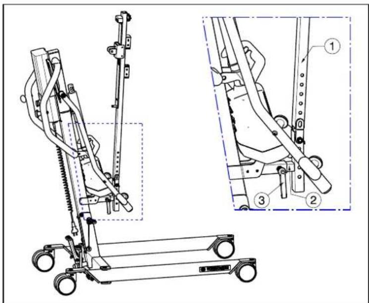
natural_image
Technical line drawing of a mobile medical support system with two views (dashed and solid) showing internal components and shafts (no text or labels)natural_image
Technical line drawing of a mobile medical or robotic device with wheels and mechanical arms (no text or symbols)natural_image
Mechanical component diagram showing a rotating arm with a curved arrow indicating rotational motion (no text or symbols)natural_image
Line drawing of a mobile vacuum cleaner with attached control panel and wheels (no text or symbols)natural_image
Technical line drawing of a mobile exercise stand with two views (dual and zoomed-in) showing mechanical components and tubing (no text or symbols present)
natural_image
Technical line drawing of a mechanical lift with three zoomed-in views (no text or symbols)natural_image
Mechanical assembly diagram showing a lever mechanism with no visible text or symbolsnatural_image
Mechanical linkage diagram showing a lever mechanism with no text or symbolsnatural_image
Technical line drawing of a mechanical bracket assembly (no text or symbols)natural_image
Four white industrial cutting tool holders with red calipers, shown from different angles (no text or symbols visible)natural_image
Mechanical assembly diagram showing a cart with wheels and directional arrows indicating motion (no text or symbols)natural_image
Mechanical device with a rotating wheel and directional arrow indicating motion (no text or symbols)natural_image
Close-up of a bicycle support frame with metal frame and black seat (no visible text or symbols)natural_image
Person in a wheelchair using an exercise machine (no visible text or symbols)natural_image
Person in wheelchair using a mobility exercise machine, with inset diagrams showing mechanical components (no text or symbols)natural_image
Person using a mobility exercise machine (no visible text or symbols)natural_image
Exterior view of a white industrial mechanical component with a red knob, shown in an oval detail (no text or symbols visible)natural_image
Exterior view of a white industrial cutting tool with a red knob and mounting bracket (no text or symbols visible)natural_image
Exterior view of a rectangular electronic device casing with mounting holes and internal compartments (no text or symbols visible)natural_image
Close-up of a white industrial robotic arm with a red button and blue arrow indicating rotation (no text or symbols visible)natural_image
Mechanical component with a cylindrical shaft and base, labeled with number 1 (no text or symbols on the object itself)natural_image
Technical line drawing of a mechanical assembly with no visible text or symbolsnatural_image
Technical line drawing of a mechanical suspension system with wheels and a curved arrow indicating motion (no text or symbols)natural_image
Technical line drawing of a mechanical assembly with wheels and linkages (no text or symbols)natural_image
Technical line drawing of a mobile exercise stand with two views (dual and zoomed-in) showing mechanical components and wiring (no text or symbols present)natural_image
Technical line drawing of a mobile crane with wheels and overhead suspension (no text or symbols)natural_image
Mechanical component diagram showing a rotating arm with directional arrow (no text or symbols)natural_image
Technical line drawing of a mechanical lift or lift support system with directional arrows indicating motion (no text or symbols present)natural_image
Technical line drawing of a mobile medical or robotic device with two views (top and side), no visible text or symbols.natural_image
Mechanical assembly diagram showing a lever mechanism with no visible text or symbolsnatural_image
Mechanical linkage diagram showing a lever mechanism with no text or symbolsnatural_image
Technical line drawing of a mechanical bracket assembly (no text or symbols)natural_image
Three white industrial cylindrical components with red caps and green safety tags, shown from different angles (no text or symbols visible)natural_image
Mechanical assembly diagram showing a cart with wheels and a curved arrow indicating motion (no text or symbols)natural_image
Mechanical assembly diagram showing a rotating wheel with directional arrow (no text or symbols)natural_image
Close-up of a bicycle support frame with metal frame and black seat (no visible text or symbols)natural_image
Person in a wheelchair using an exercise machine (no visible text or symbols)natural_image
Person in a wheelchair using an eotard bridge, with an inset diagram showing mechanical components (no text or symbols present)natural_image
Person using a medical or rehabilitation device on a wheeled platform (no visible text or symbols)3.3 Batería y carga
3.3.1 Batería

natural_image
Close-up of a white industrial component with a red cap and blue outline, no visible text or symbolsnatural_image
Exterior view of a white industrial machine component with a red indicator knob, shown in an oval (no text or symbols visible)natural_image
Exterior view of a white plastic enclosure or casing with mounting holes and a small circular component (no text or symbols visible)natural_image
Close-up of a white robotic arm with a red button and blue arrow indicator (no text or symbols)natural_image
Mechanical component with a cylindrical shaft and base, labeled with number 1 and an arrow pointing to it (no text or symbols beyond labels)natural_image
Technical line drawing of a mechanical device with internal components and directional arrows indicating motion (no text or symbols)natural_image
Technical line drawing of a mechanical assembly with no visible text or symbolsnatural_image
Mechanical linkage system diagram showing two wheels and a curved arrow indicating motion (no text or symbols)natural_image
Technical line drawing of a mechanical linkage system with pulleys and joints (no text or symbols)natural_image
Technical line drawing of a mechanical lift with three views (no text or symbols)natural_image
Technical line drawing of a mobile exercise stand with two views (① and ②), no text or symbols present.natural_image
Technical line drawing of a mechanical lift or support system with wheels and guide rails (no text or symbols)natural_image
Mechanical component diagram showing a rotating arm with directional arrow (no text or symbols)natural_image
Line drawing of a mobile vacuum cleaner with attached control panel and wheels (no text or symbols)natural_image
Technical line drawing of a mobile medical or robotic device with two views (top and side), no visible text or symbols.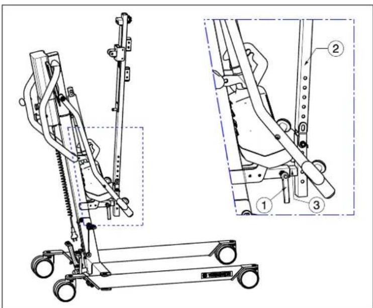
natural_image
Mechanical assembly diagram showing a lever mechanism with a gray arrow indicating motion direction (no text or symbols present)natural_image
Mechanical linkage diagram showing a lever mechanism with no text or symbolsnatural_image
Mechanical assembly diagram showing bracket and mounting components (no text or labels)natural_image
Four white industrial cutting tool holders with red calipers, shown from different angles (no text or symbols visible)natural_image
Mechanical assembly diagram showing a cart with wheels and a curved arrow indicating motion (no text or symbols)natural_image
Mechanical device with a curved arrow indicating rotational motion (no text or symbols)natural_image
Close-up of a bicycle seatbelt mechanism with metal frame and black belt (no visible text or symbols)natural_image
Person in a wheelchair using a stationary exercise machine (no visible text or symbols)natural_image
Person in a wheelchair using an exercise machine, with an inset diagram showing mechanical components (no text or symbols present)natural_image
Person using a mobility exercise machine (no visible text or symbols)
natural_image
Exterior view of a white industrial machine component with a red knob, shown in an oval detail (no text or symbols visible)natural_image
Close-up of a white industrial cutting tool component with a red knob, shown in an oval view (no text or symbols visible)natural_image
Exterior view of a white plastic enclosure with circular cutouts and mounting feet (no text or symbols)natural_image
Close-up of a white robotic arm with a red button and blue arrow symbol (no text or labels visible)natural_image
Close-up of a mechanical component with a cylindrical shaft and base, labeled with number 1 (no text or symbols on the object itself)natural_image
Technical line drawing of a mechanical assembly with internal components and a downward arrow (no text or symbols)natural_image
Mechanical component diagram showing rotational motion with no text or symbolsnatural_image
Technical line drawing of a mechanical bracket assembly (no text or symbols)natural_image
Technical line drawing of a mechanical suspension system with wheels and a curved component (no text or symbols)natural_image
Technical line drawing of a mechanical linkage system with pulleys and joints (no text or symbols)natural_image
Technical line drawing of a mobile medical or robotic device with labeled parts, shown from two different angles (no text or symbols present)natural_image
Technical line drawing of a mechanical lift or support system with wheels and guide rails (no text or symbols)natural_image
Mechanical component diagram showing rotational motion with no text or symbolsnatural_image
Line drawing of a mobile vacuum cleaner with attached control panel and wheels (no text or symbols)natural_image
Technical line drawing of a mobile medical support system with two views (top and side), no visible text or symbolsnatural_image
Mechanical assembly diagram showing a lever mechanism with no visible text or symbolsnatural_image
Mechanical linkage mechanism diagram showing motion arrows and joints (no text or symbols)natural_image
Technical line drawing of a mechanical bracket assembly (no text or symbols)natural_image
Four white industrial cylindrical components with red connectors, shown from different angles (no text or symbols visible)natural_image
Mechanical assembly diagram showing a wheel-mounted frame with directional arrows indicating motion (no text or symbols)natural_image
Mechanical assembly diagram showing a rotating wheel and lever mechanism with directional arrow (no text or symbols)natural_image
Close-up of a bicycle seat frame with metal frame and black seat (no visible text or symbols)natural_image
Person in a wheelchair using a stationary exercise machine (no visible text or symbols)natural_image
Person in wheelchair using a mobility exercise machine, with inset diagrams showing structural details (no text or symbols)natural_image
Person using a mobility exercise machine (no visible text or symbols)
natural_image
Close-up of a white industrial mechanical component with a red knob, shown in an oval detail (no text or symbols visible)natural_image
Close-up of a white industrial cutting tool with a red knob, shown in an oval view (no text or symbols visible)natural_image
Exterior view of a white plastic enclosure with mounting holes and internal compartments (no text or symbols)natural_image
Close-up of a white robotic arm with a red button and blue arrow indicator (no text or symbols)natural_image
Mechanical component with a cylindrical shaft and base, labeled with number 1 and an arrow pointing to it (no text or symbols on the object itself)natural_image
Diagram of a vehicle chassis inside a vehicle cabin with a downward arrow indicating motion (no text or symbols)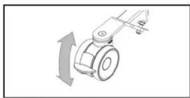
natural_image
Mechanical component diagram showing a rotating arm with directional arrow (no text or symbols)natural_image
Technical line drawing of a mechanical assembly with no visible text or symbolsnatural_image
Technical line drawing of a mechanical suspension or lifting mechanism with wheels and a curved arrow indicating motion (no text or symbols)natural_image
Technical line drawing of a mechanical assembly with levers and wheels (no text or symbols)natural_image
Technical line drawing of a mechanical lift with three views (①, ②, ③) showing different components and motion directions (no text or symbols present)natural_image
Technical line drawing of a mobile exercise stand with two views (dashed and solid) showing internal components and shafts (no text or labels)natural_image
Technical line drawing of a mechanical lift or lift support system with no visible text or symbolsnatural_image
Mechanical component diagram showing a rotating arm with a curved arrow indicating rotational motion (no text or symbols)natural_image
Line drawing of a vacuum cleaner with attached equipment and directional arrows indicating motion (no text or symbols)natural_image
Technical line drawing of a mobile exercise stand with two views (dual and zoomed-in) showing mechanical components and wiring (no text or symbols present)natural_image
Mechanical assembly diagram showing a lever mechanism with no visible text or symbolsnatural_image
Mechanical linkage diagram showing a lever mechanism with no text or symbolsnatural_image
Technical line drawing of a mechanical bracket assembly (no text or symbols)natural_image
Four white industrial cylindrical components with red connectors, shown from different angles (no text or symbols visible)Service registration form
This product (name): ....
was inspected (I), serviced (S), repaired (R) or disinfected (D):
| By (stamp):Kind of work: I / S / R / DDate: | By (stamp):Kind of work: I / S / R / DDate: | By (stamp):Kind of work: I / S / R / DDate: |
| By (stamp):Kind of work: I / S / R / DDate: | By (stamp):Kind of work: I / S / R / DDate: | By (stamp):Kind of work: I / S / R / DDate: |
| By (stamp):Kind of work: I / S / R / DDate: | By (stamp):Kind of work: I / S / R / DDate: | By (stamp):Kind of world: I / S / R / DDate: |
| By (stamp):Kind of work: I / S / R / DDate: | By (stamp):Kind of work: I / S / R / DDate: | By (stamp):Kind of work: I / S / R / DDate: |
| By (stamp):Kind of work: I / S / R / DDate: | By (stamp):Kind of work: I / S /R / DDate: | By (stamp):Kind of work: I / S / R / DDate: |
| By (stamp):Kind of work: I / S / R / DDate: | By (stamp):Kind of work: I / S / R / DDate: | By (stamp):Kind of work: I / S / R / DDate: |

Vermeiren GROUP
Vermeirenplein 1 / 15
2920 Kalmthout
BE
website: www.vermeiren.com

- EN
- Instructions for specialist dealer
- FR
- Contents
- Contents....1
- Preface....2
- Your product....3
- Before use ....4
- Using the patient hoist ....5
- Installation and adjustment....13
- Maintenance....21
- Troubleshooting....24
- Technical specifications....25
- Preface
- Important note
- Information available
- Your product
- Before use
- Intended Use
- General safety instructions
- Using the patient hoist
- Operating the lift
- CAUTION
- Risk of injuries and/or damage
- Altering the chassis width
- Parking brakes
- Footplate
- Leg support
- Thorax support
- Raising and lowering the cantilever arm
- Moving the patient hoist
- Turn the patient hoist around his axle
- Slings
- Risk of injuries
- Attachment points on patient lift
- Instructions for lifting patient
- Battery and charging
- Battery
- Control box + included battery charger
- External charger (OPTIONAL)
- Charging the batteries
- First use
- Recharging
- Emergency
- Emergency stop
- Emergency lowering
- Installation and adjustment
- Delivery
- Assembly or dismantling
- Unpacking
- Assembly
- Dismantling
- Changing the battery
- Maintenance
- Time of maintenance
- Before each use
- Approx. every 8 weeks
- Yearly or more often
- Shipping and storage
- Cleaning
- Plastic parts
- Coating
- Electronics casing
- Disinfection
- Inspection
- Expected lifespan
- Reuse
- End of use
- Troubleshooting
- Technical specifications
- Table des matières
- Batterij en laden
- Batterij
- Montage en afstelling
- Beinstütze
- DE
- Batería y carga
- Batería
- Service registration form
Brand : Vermeiren
Model : Albatros II
Category : Chair