IRM 320W - Heating DIMPLEX - Free user manual and instructions
Find the device manual for free IRM 320W DIMPLEX in PDF.


| Product type | Infrared heater |
| Brand | Dimplex |
| Model | IRM 320W |
| Rated thermal power | 0.32 kW |
| Minimum thermal power | 0.32 kW |
| Maximum continuous thermal power | 0.32 kW |
| Rated voltage | 230 V ~, 1/N/PE |
| Protection rating | IPx4 (protected against water splashes) |
| Dimensions (W x H x D) | 620 x 620 x 24 mm |
| Weight | 7.5 kg |
| Mounting type | Vertical or horizontal, wall or ceiling |
| Minimum distance from flammable objects | 400 mm in front, 200 mm on sides and top |
| Minimum height for ceiling mounting | 2.5 m |
| Electrical connection | Fixed connection, requires a circuit breaker with contact opening ≥ 3 mm |
| Required room thermostat | External, recommended Dimplex DTB 2R with weekly programming |
| Safety functions | Overload limiter, automatic shutdown in case of overheating |
| Maintenance | Clean with a soft brush, do not use liquids or chemicals |
| Warranty | 5 years |
| Disposal | Do not dispose with household waste, take to a recycling center |
| Number of models in series | Four: 320W, 650W, 800W, 1000W |
| Certification | Complies with VDE 100-701 standards for protection zones |
Frequently Asked Questions - IRM 320W DIMPLEX
User questions about IRM 320W DIMPLEX
0 question about this device. Answer the ones you know or ask your own.
Ask a new question about this device
Download the instructions for your Heating in PDF format for free! Find your manual IRM 320W - DIMPLEX and take your electronic device back in hand. On this page are published all the documents necessary for the use of your device. IRM 320W by DIMPLEX.
USER MANUAL IRM 320W DIMPLEX
natural_image
Plain white rectangular panel with a thin gray border, no text or symbols visible.DCDimplex
| Montage- und Gebrauchsanweisung | DeutschEng |
| Installation and Operating Instructions | Françaisitalano |
| Instructions de montage et d’utilisation | |
| Istruzioni d’uso e di montaggio | Polski |
| Instrukcja montażu i użytkowania |
| Metall-Infrarotheizung |
| Metal infrared heater |
| Chauffage infrarouge métallique |
| Riscaldamento a infrarossi in metallo |
| Metalowy grzejnik na podczerwień |
1. Notes for the user
NOTE
Dear customer,
Keep these instructions in a safe place and pass them on to possible future owners.
ATTENTION!
This device can be used by children aged 8 and over and by persons with limited physical, sensory or mental aptitude or lack of experience and/or knowledge, providing they are supervised or have been instructed in the safe use of the device and understand the associated potential dangers. Children must not play with the unit. Cleaning and maintenance may not be carried out by children without supervision!
ATTENTION!
Children of less than 3 years should be kept away unless continuously supervised! Children between the ages of 3 and 8 may switch the device on and off if they are supervised or have been instructed in the safe use of the device and have understood the resulting dangers, providing that the device is positioned or installed in its normal place of use!
ATTENTION!
Children between the ages of 3 and 8 may not switch on the device, clean the device or carry out maintenance!
ATTENTION!
To avoid overheating, do not cover the heating device.
ATTENTION!
Some parts of the device can get very hot and cause burns. Particular caution must be taken with children or vulnerable people!
ATTENTION!
Install the device in such a manner that it cannot be touched by a person in the bathtub or under the shower.
ATTENTION!
If the power cable is damaged, it must be replaced by the manufacturer so as to eliminate potential dangers.
2. Assembly
ATTENTION!
The original brackets provided must be used.
These devices can be mounted vertically or horizontally onto the wall or the ceiling.
They must be mounted so that flammable objects can not be ignited.
When installing the heating device with mains power socket and room thermostat, the protection zone in accordance with VDE 100-701 must be observed.
Drilling dimensions, power cable
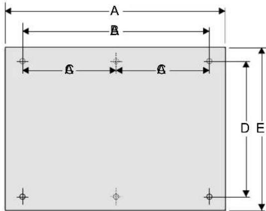
View of the front
| Model | Dimen-sion A mm | Dimen-sion B mm | Dimen-sion C mm | Dimen-sion D mm | Dimen-sion E mm |
| IRM 320W 620 440 - 440 620 | |||||
| IRM 650W 1220 1040 | 520 440 | 620 | |||
| IRM 800W 1520 1340 | 670 440 | 620 | |||
| IRM 1000W 1520 1340 | 670 600 | 770 | |||
ATTENTION!
Do not install the device directly below a wall socket.
Installation on wooden walls is permissible.
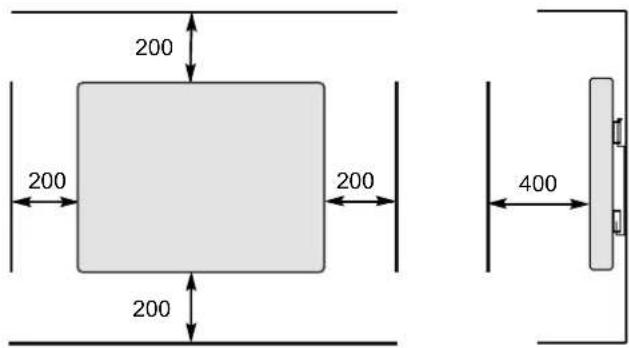
The heating device must be installed on a vertical wall (see illustration). The minimum clearances must be observed. In addition, a clearance of 400 mm is to be maintained in front of the unit. All dimensions in mm.
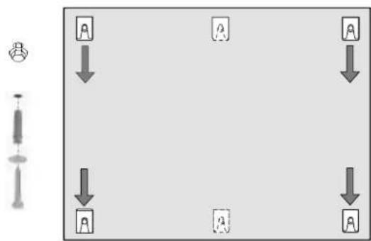
■ Mark, drill and plug the fixing holes.
- Fix the screws with washers into the wall. Allow for a clearance of up to 4 mm to mount the wall bracket.
■ Align the wall bracket as depicted in the illustration and mount the heating device in the bracket.
flowchart
graph TD
    A["Input Node 1"] --> B["Output Node 1"]
    C["Input Node 2"] --> D["Output Node 2"]
    E["Input Node 3"] --> F["Output Node 3"]
    G["Input Node 4"] --> H["Output Node 4"]
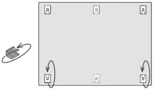
■ Turn two of the wall brackets by approx. 180° to act as safety catches.
■ Tighten the fastening screws on the heating device (width across flats 8 mm) and the fastening screws on the wall (width across flats 10 mm).
flowchart
graph TD
    A["Device 1"] --> B["Block 1"]
    B --> C["Block 2"]
    C --> D["Block 3"]
    D --> E["Block 4"]
Ceiling mounting
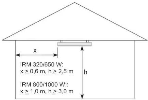
The heating device must be installed on a horizontal ceiling (see illustration). Dimensions x and h are recommendations for ensuring a pleasant distribution of heat and can be adjusted if required (observe the minimum clearances).
3. Electrical connection
The voltage specified on the type plate must match the line voltage.
It is recommended that a separate electric circuit be provided for the power supply.
The heating device is designed for fixed connection to a wall socket. When mounting on a wall, route the device connection cable downwards.
The device must only be installed and repaired by a qualified electrician in accordance with the applicable safety regulations.
Connection may only take place on securely routed cables!
A disconnecting device with a contact opening of at least 3 mm at each pole (e.g. circuit breaker) must be provided in the installed wiring.
4. Heating operation
NOTE
Only use the device for room heating within enclosed rooms.
Operation of the heating device is only permissible if it is in conjunction with an external room thermostat with the following functions:
■ electronically controlled week programme,
■ adaptive control of the heating start,
■ further energy-saving functions.
Please observe the operating instructions for the room thermostat.
Recommended room thermostat: Dimplex DTB 2R.
5. Faults
If the heating device is not emitting any heat, check the temperature setting on the room thermostat, then check whether the fuse in the electricity distribution is switched on.
For your safety, the heating device is equipped with an integrated overload protector. The device switches off automatically in the case of impermissible heating of the heating device (e.g. due to it being hung or positioned incorrectly).
Before recommissioning, remove the causes behind the overload protector being triggered.
Once the device has cooled down sufficiently, the overload protector closes again automatically and the device can be operated again.
If you cannot correct the fault, please contact a specialist electrical service centre or else the service centre for Dimplex devices. Please have the E-number printed on the type plate ready.
6. Cleaning
The device must be switched off and must have cooled down before cleaning. Set the room thermostat to OFF. Clean the outside of the device using a soft hand brush.
Do not use any fluid, scouring powder or other chemicals, as they could damage the surface.
7. Warranty
This product is supplied with a five-year warranty according to our terms of guarantee.
8. Note on disposal
Do not dispose of the device with general household waste. The device must be taken to a local waste disposal plant.

9. Technical data
| Unit type | IRM 320W IRM 6 | 50W IRM 800W IRM 10 | 000W | ||
| Nominal voltage | 1/N/PE, 230 V~ | ||||
| Degree of protection | IPx4, splash-proof | ||||
| Dimensions (W x H x D) | 620 x 620 x 24 mm 1 | 220 x 620 x 24 mm 152 | 0 x 620 x 24 mm 1520 | x 770 x 24 mm | |
| Weight | 7.5 kg 13.5 kg | 17.0 kg 21.0 kg | |||
| Heat output | |||||
| Nominal heat output | P_nom | 0.32 kW | 0.65 kW | 0.80 kW | 1.00 kW |
| Minimum heat output (Reference value) | P_min | 0.32 kW | 0.65 kW | 0.80 kW | 1.00 kW |
| Maximum continuous heat output | P_max | 0.32 kW | 0.65 kW | 0.80 kW | 1.00 kW |
| Self consumption | |||||
| With nominal heat output | el_max | 0.00 W | 0.00 W | 0.00 W | 0.00 W |
| With minimum heat output | el_min | 0.00 W | 0.00 W | 0.00 W | 0.00 W |
| In standby state | el_SB | 0.00 W | 0.00 W | 0.00 W | 0.00 W |
| Regulator for heat output | |||||
| External electronic room temperature controllers with week programme and adaptive control of the heating start, as well as other energy saving functions where applicable. | |||||
Vue de l'avant
| Modèles | Cote A mm | Cote B mm | Cote C mm | Cote D mm | Cote E mm |
| IRM 320W 620 | 440 - 440 | 620 | |||
| IRM 650W 1220 | 1040 | 520 440 | 620 | ||
| IRM 800W 1520 | 1340 | 670 440 | 620 | ||
| IRM 1000W 1520 | 1340 | 670 600 | 770 |
ATTENTION!
Vista lato anteriore
| Modelli | DimensioniA mm | DimensioniB mm | DimensioniC mm | DimensioniD mm | DimensioniE mm |
| IRM 320W 620 440 - 440 620 | |||||
| IRM 650W 1220 1040 | 520 440 | 620 | |||
| IRM 800W 1520 1340 | 670 440 | 620 | |||
| IRM 1000W 1520 1340 | 670 600 | 770 | |||
ATTENZIONE!
Brand : DIMPLEX
Model : IRM 320W
Category : Heating