76833 - Basket KENMORE - Free user manual and instructions
Find the device manual for free 76833 KENMORE in PDF.

| Product Type | Gas range with oven |
| Brand | Kenmore |
| Model | 76833 (series 982.7683#) |
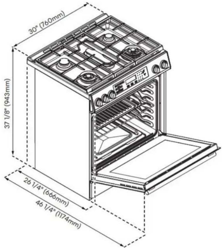
| Dimensions (W x D x H) | 76.2 cm x 94.3 cm x 117.4 cm |
| Weight | Approximately 70 kg |
| Electrical supply | 120 V, 60 Hz, 15 A (3-prong grounded plug) |
| Gas supply | Natural gas (convertible to propane with optional kit) |
| Surface burners | 5 burners: auxiliary, semi-rapid, rapid, triple ring, oval |
| Ignition | Electronic (manual ignition possible in case of power outage) |
| Oven functions | Bake, Broil, Warm/Proof |
| Oven temperature range | 77 – 288 °C (170 – 550 °F) |
| Oven light | Standard 25 W bulb (G9) |
| Materials | Stainless steel, enamel, porcelain on grates and burner caps |
| Cleaning | Surface: mild cleaner; oven: mild detergent (no self-cleaning oven cleaner) |
| Safety | Anti-tip device, flame detection, child lock (hold Start 3s) |
| Spare parts | Grates, burner caps, diffusers, bulbs, oven heating elements |
| Repairability | Repair by qualified technician; parts available from Kenmore |
| General information | Kenmore limited warranty; installation by a professional |
Frequently Asked Questions - 76833 KENMORE
User questions about 76833 KENMORE
0 question about this device. Answer the ones you know or ask your own.
Ask a new question about this device
Download the instructions for your Basket in PDF format for free! Find your manual 76833 - KENMORE and take your electronic device back in hand. On this page are published all the documents necessary for the use of your device. 76833 by KENMORE.
USER MANUAL 76833 KENMORE
In the space below, record the date of purchase, model and serial number of your product. You will find the model and serial number printed on an identification label located on the inside right lip of the oven cavity. Have these items of information available whenever you contact Sears concerning your product.
Model No. Date of Purchase
Serial No.
Save these instructions and attach your sales receipt for future reference.
Kenmore Limited Warranty
Kenmore ^® products are sold and distributed by Kenmore and Kenmore authorized distributors and licensees in various countries.
For information on the limited warranty and authorized provider applicable to your product and country please visit: https://www.kenmore.com/warranty-information/
For a printed copy please contact us at 1-844-553-6667 or at the address below:
ATTN: Kenmore Warranty Request
5407 Trillium Suite B120
Hoffman Estates, IL 60192
TABLE OF CONTENTS
RANGE SAFETY....6
OVERVIEW....13
CONTROL PANEL....15
COOKTOP USE....18
OVEN USE....20
RANGE CARE....25
TROUBLESHOOTING....29
Installation Requirements....32
Installation Instructions....44
WARNING

Fire Hazard
If the information in this manual is not followed exactly, a fire or explosion may result causing property damage, personal injury or death.
- Do not store or use gasoline or other flammable vapors and liquids in the vicinity of this or any other appliance.
- WHAT TO DO IF YOU SMELL GAS
• Do not try to light any appliance.
• Do not touch any electrical switch.
• Do not use any phone in your building.
• Clear the room, building, or area of all occupants.
- Immediately call your gas supplier from a neighbor's phone. Follow the gas supplier's instructions.
• If you cannot reach your gas supplier, call the fire department.
- Installation and service must be performed by a qualified installer, service agency or the gas supplier.
WARNING
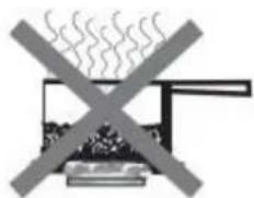
Never Operate the Top Surface Cooking Section of this Appliance Unattended.
- Failure to follow this warning statement could result in fire, explosion, or burn hazard that could cause property damage, personal injury, or death.
- If a fire should occur, keep away from the appliance and immediately call your fire department.
DO NOT ATTEMPT TO EXTINGUISH AN OIL/GREASE FIRE WITH WATER
THE ANTI-TIP BRACKET
WARNING
natural_image
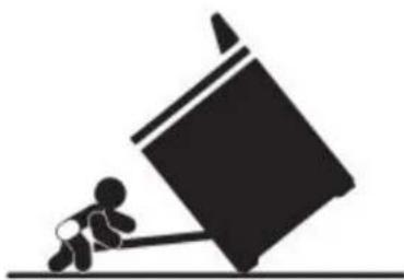
Silhouette of a person pushing a large object on a flat surface (no text or symbols)Tip Over Hazard
A child or adult can tip the range and be killed.
Connect anti-tip bracket to rear range foot.
Reconnect the anti-tip bracket, if the range is moved.
See the installation instructions for details.
Failure to follow these instructions can result in death or serious burns to children and adults.
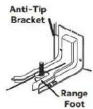
Making sure the anti-tip bracket is installed:
- Slide range forward.
- Look for the anti-tip bracket securely attached to floor.
- Slide range back so rear range foot is under anti-tip bracket.
WARNING Gas leaks cannot always be detected by smell.
Gas suppliers recommend that you use a gas detector approved by UL or CSA. For more information, contact your gas supplier.
WARNING Do not install a ventilation system that blows air downward toward this cooking appliance. This type of ventilation system may cause ignition and combustion problems with this cooking appliance resulting in personal injury or unintended operation.
Your safety and the safety of others are very important.
We have provided many important safety messages in this manual and on your appliance. Always read and obey all safety messages.

This is the safety alert symbol.
This symbol alerts you to potential hazards that can kill or hurt you and others.
All safety messages will follow the safety alert symbol and either the word "DANGER," "WARNING" or "CAUTION." These words mean:
| DANGER | You can be killed or seriously injured if you don't immediately follow instructions. |
| WARNING | You can be killed or seriously injured if you don't follow instructions. |
| CAUTION | A potentially hazardous situation which, if not avoided, could result in minor or moderate injury. |
All safety messages will tell you what the potential hazard is, tell you how to reduce the chance of injury, and tell you what can happen if the instructions are not followed.
In the State of Massachusetts, the following installation instructions apply:
• Installations and repairs must be performed by a qualified or licensed contractor, plumber, or gasfitter qualified or licensed by the State of Massachusetts.
• If using a ball valve, it shall be a T-handle type.
• A flexible gas connector, when used, must not exceed 3 feet.
State of California Proposition 65 Warnings:

WARNING This product contains bisphenol A(BPA), which is known to the state of
California to cause birth defects, or other reproductive harm, and lead and lead compounds, which are known to the state of California to cause cancer and birth defects or other reproductive harm.
For more information, go to : www.P65Warnings.ca.gov.
IMPORTANT SAFETY INSTRUCTIONS
WARNING To reduce the risk of fire, electrical shock, injury to persons, or damage when using the range, follow basic precautions, including the following:
- WARNING TO REDUCE THE RISK OF TIPPING OF THE RANGE, THE RANGE MUST BE SECURED BY PROPERLY INSTALLED ANTI-TIP DEVICES. TO CHECK IF THE DEVICES ARE INSTALLED PROPERLY, SLIDE RANGE COMPLETELY FORWARD, LOOK FOR ANTI-TIP BRACKET SECURELY ATTACHED TO THE FLOOR OR WALL, AND SLIDE RANGE BACK SO THE REAR RANGE FOOT IS UNDER ANTI-TIP BRACKET.
- WARNING NEVER use this appliance as a space heater to heat or warm the room. Doing so may result in carbon monoxide poisoning and overheating of the oven.
- WARNING NEVER cover any slots, holes or passages in the oven bottom or cover an entire rack with materials such as aluminum foil. Doing so blocks airflow through the oven and may cause carbon monoxide poisoning. Aluminum foil linings may also trap heat, causing a fire hazard.
- CAUTION Do not store items of interest to children in cabinets above a range or on the back guard of a range - children climbing on the range to reach items could be seriously injured. - Do Not Leave Children Alone - Children should not be left alone or unattended in area where range is in use. They should never be allowed to sit or stand on any part of the range.
- Wear Proper Apparel – Loose fitting or hanging garments should never be worn while using the range.
- User Servicing – Do not repair or replace any part of the range unless specifically recommended in the manual. All other servicing should be referred to a qualified technician.
- Storage in or on Range – Flammable materials should not be stored in an oven or near surface units.
- This appliance is not intended for storage.
READ AND SAVE THESE INSTRUCTIONS
IMPORTANT SAFETY INSTRUCTIONS
- Do Not Use Water on Grease Fires - Smother fire or flame or use dry chemical or foam-type extinguisher.
- Use Only Dry Potholders - Moist or damp potholders on hot surfaces may result in burns from steam. Do not let potholder touch hot heating elements. Do not use a towel or other bulky cloth.
- Never Leave Surface Units Unattended at High Heat Settings – Boilover causes smoking and greasy spillovers that may ignite.
- Glazed Cooking Utensils – Only certain types of glass, glass/ceramic, ceramic, earthenware, or other glazed utensils are suitable for range top service without breaking due to the sudden change in temperature.
- Utensil Handles Should Be Turned Inward and Not Extend Over Adjacent Surface Units - To reduce the risk of burns, ignition of flammable materials, and spillage due to unintentional contact with the utensil, the handle of a utensil should be positioned so that it is turned inward, and does not extend over adjacent surface units.
- Disconnect power before servicing.
- Proper Installation – The appliance, when installed, must be electrically grounded in accordance with local codes, or in the absence of local codes, with the National Electrical Code, ANSI/NFPA 70 or the Canadian Electrical Code, CSA C22.1-02. In Canada, the appliance must be electrically grounded in accordance with Canadian Electrical Code. Be sure your appliance is properly installed and grounded by a qualified technician.
- Injuries may result from misuse of appliance doors or drawers such as stepping, leaning, or sitting on the doors or drawers.
- Maintenance – Keep range area clear and free from combustible materials, gasoline, and other flammable vapors and liquids.
- Do not let cooking grease or other flammable materials accumulate in or near the range. Grease in the oven or on the cooktop may ignite.
- Top burner flame size should be adjusted so it does not extend beyond the edge of the cooking utensil. This instruction is based on safety considerations.
READ AND SAVE THESE INSTRUCTIONS
IMPORTANT SAFETY INSTRUCTIONS
- Do not use replacement parts that have not been recommended by the manufacturer (e.g. parts made at home using a 3D printer).
- Clean Cooktop With Caution – If a wet sponge or cloth is used to wipe spills on a hot cooking area, be careful to avoid steam burn. Some cleaners can produce noxious fumes if applied to a hot surface.
- Use Care When Opening Door - Let hot air or steam escape before removing or replacing food.
- Do Not Heat Unopened Food Containers - Build-up of pressure may cause container to burst and result in injury.
- Keep Oven Vent Ducts Unobstructed.
- Never broil with door open. Open-door broiling is not permitted due to overheating of control knobs.
-
Placement of Oven Racks – Always place oven racks in desired location while oven is cool. If rack must be moved while oven is hot, do not let potholder contact hot heating element in oven.
-
Care must be taken to prevent aluminum foil and meat probes from contacting heating elements.
- DO NOT TOUCH HEATING ELEMENTS OR INTERIOR SURFACES OF OVEN – Heating elements may be hot even though they are dark in color. Interior surfaces of an oven become hot enough to cause burns. During and after use, do not touch, or let clothing or other flammable materials contact heating elements or interior surfaces of oven until they have had sufficient time to cool. Other surfaces of the appliance may become hot enough to cause burns – among these surfaces are cooktop, burners, grates, oven vent openings and surfaces near these openings, oven doors, windows of oven doors, and crevices around the oven doors.
- Top burner flame size should be adjusted so it does not extend beyond the edge of the cooking utensil.
- Have the installer show you the location of the range gas shut-off valve and how to turn it off if necessary.
READ AND SAVE THESE INSTRUCTIONS
IMPORTANT SAFETY INSTRUCTIONS
- Proper Disposal of Your Appliance - Dispose of or recycle your appliance in accordance with Federal and Local Regulations. Contact your local authorities for the environmentally safe disposal or recycling of your appliance.
For units with ventilating hood - - Clean Ventilating Hoods Frequently - Grease should not be allowed to accumulate on hood or filter. - When flambé cooking under the vent hood, turn the fan on.
For self-cleaning ranges - - Do Not Clean Door Gasket - The door gasket is essential for a good seal. Care should be taken not to rub, damage, or move the gasket. - Do Not Use Oven Cleaners - No commercial oven cleaner or oven liner protective coating of any kind should be used in or around any part of the oven. - Clean Only Parts Listed in Manual. - Before Self-Cleaning the Oven - Remove broiler pan and other utensils. Wipe off all excessive spillage before initiating the cleaning cycle.
READ AND SAVE THESE INSTRUCTIONS
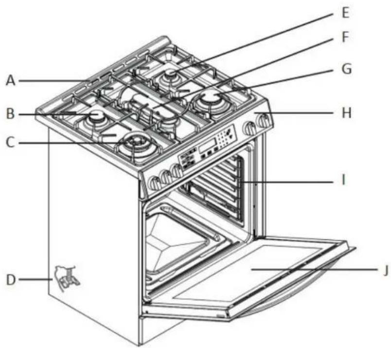
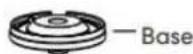
A Backsplash
B Semi-Rapid Burner
C Triple Burner
D Anti-tip Bracket
E Auxiliary Burner
F Oval Burner
G Rapid Burner
H Control Panel
I Oven Rack Positions
J Oven Door Window
BURNER LAYOUT
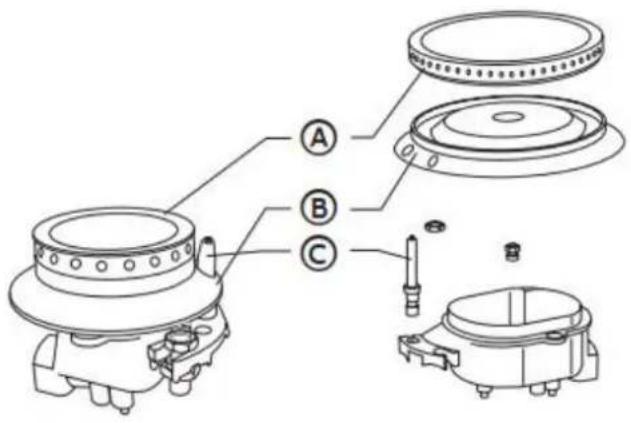
A Burner Cap
B Burner Head
C Electrode
CONTROL PANEL
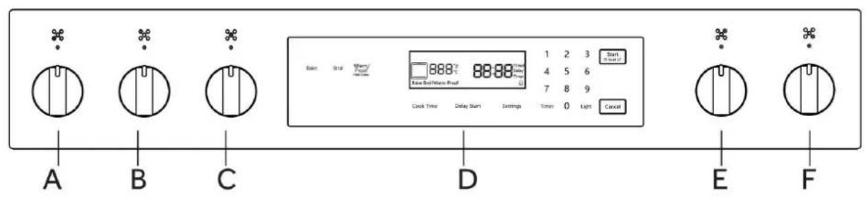
A Front Left Burner
B Rear Left Burner
C Oven Touch Control
C Middle Burner
D Rear Right Burner
E Front Right Burner

G Cook Time
H Delay Start
I Settings
J Timer
K Light
L Start/Control Lock (hold 3 seconds)
M Cancel
N Display

Child lock icon – After holding "Start" button for 3 seconds, the icon will appear on the display.
IMPORTANT: Clock must be set in order for the timed oven functions to work.
NOTE: In the event of a power failure, all settings including the clock time set will be lost.
When the power is returned, clock must be set again.
Oven Settings Guide
Clock
- Press "Settings" repeatedly until the display shows "---:-- Timed".
- Press numbers to enter the time.
- Press "Start" to save.
Selecting Fahrenheit or Celsius
- Press "Settings" repeatedly until "Unit" appears in the display.
- Press "1" to select F (Fahrenheit) or (Celsius).
- Press "Start" to save.
Sound
- Press "Settings" repeatedly until "Snd" appears in the display.
- Press "1" to select On or Off.
- Press "Start" to save.
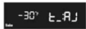
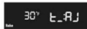
Adjusting the Oven Temperature
- Press "Settings" repeatedly until "t_AJ" appears in the display.
- Press "1" to select the mode you want to adjust temperature.
- Press "3" or "6" to select the temperature.
- Press "Start" to save.
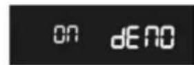
Demo mode
- Press "Settings" repeatedly until "dEno" appears in the display.
- Press "1" to select On or Off.
- Press "Start" to save.


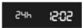
Setting the Hour Mode
- Press "Settings" repeatedly until "12h" or "24h" appears in the display.
- Press "1" to select "12h" or "24h".
- Press "Start" to save.
COOKTOP USE
Read the instructions before installing or using this appliance.
- This appliance shall be installed in accordance with the regulations in force and only used in a well-ventilated space.
- The use of a gas-cooking appliance results in the production of heat and moisture in the room in which it is installed. Ensure that the kitchen is well ventilated: keep natural ventilation holes open or install a mechanical ventilation device (mechanical extractor hood).
- Prolonged intensive use of the appliance may call for additional ventilation, for example opening of a window, or more effective ventilation, for example increasing the level of mechanical ventilation where present.
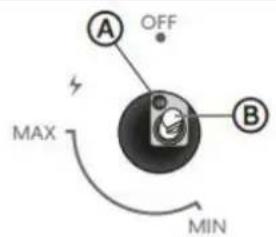
To ignite a burner, push down on the burner knob and rotate it counterclockwise until the knob indicator is aligned with the ignite icon. Release the knob and adjust the flame intensity by further rotating the knob counterclockwise from MAX (maximum) to MIN (minimum).
NOTE: For models with a flame failure safety device - Once the flame is lit, hold the knob depressed for about 3-4 seconds until the device keeps the burner automatically lit. If the burner fails to ignite, wait one minute for the gas to dissipate before attempting to reignite. To turn off the burner, rotate the knob clockwise until the indicator on the knob is aligned with OFF.
POWER FAILURE
In case of prolonged power failure, the surface burners can be lit manually. Hold a lit match near a burner and turn knob counterclockwise until the indicator is aligned with MAX. After the burner is lit, turn knob to desired setting.
In the case of unintentional flame extinguishing, the safety valve intervenes by shutting off the gas to the burners.
The electric igniter must not be actuated for longer than 15 seconds. Should the burner not light, or should the burner be unintentionally turned off, immediately close the burner, and wait at least 1 minute before repeating. Once ignited, adjust the flame as desired.
For lower gas consumption and a better result, use saucepans with a diameter matching the diameter of the burner, to avoid the flame coming up around the sides of the saucepan. See the Container Table. Use only flat-bottomed pans.
As soon as liquid starts to boil, turn the flame down to a level sufficient to maintain boiling.
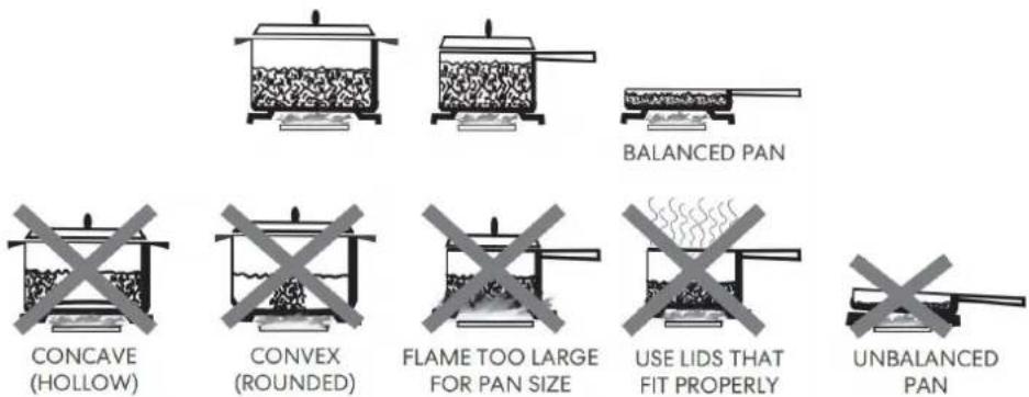
COOKWARE
MATCH PAN DIAMETER TO FLAME SIZE
The flame should be the same size as the bottom of the pan or smaller. Do not use small pans with high flame settings as the flames can lick up the sides of the pan. Oversize pans that span two burners are placed front to rear, not side to side.
USE BALANCED PANS
Pans must sit level on the cooktop grate without rocking. Center the pan over the burner.
USE A LID THAT FITS PROPERLY
A well-fitting lid helps shorten the cooking time. Flat, heavy bottom pans provide even heat and stability.
CONTAINER TABLE
| Burner | Min Saucepan | Max Saucepan |
| Auxiliary | 3.5" (9.0 cm) | 6.3" (16 cm) |
| Semi-rapid | 5.1" (13 cm) | 7.1" (18 cm) |
| Rapid | 5.9" (15 cm) | 10.2" (26 cm) |
| Triple ring | 8.3" (21 cm) | 10.2" (26 cm) |
OVEN USE
This oven includes the functions of traditional oven modes. Use the Cooking Mode control, located on the control panel, to select the oven mode.
BEFORE USING THE OVEN FOR THE FIRST TIME
- Close the oven door.
- Press Bake.
- Press 500°F (260°C) on the number keypad.
- Press Start.
NOTE: Allow the oven to operate for 30 minutes with the door closed and no food in the cavity.
- ool.
NOTE: Any odor that may be detected during this initial use is due to the evaporation of substances used to protect the oven during storage.
GENERAL
IMPORTANT: Do not place anything, including dishes, foil and oven trays, on the bottom of the oven when it is in operation to avoid damaging the enamel.
- Place bakeware with food on the rack provided with the oven.
- Close the oven door.
NOTE: The oven cannot be set with the door open.
- Press the desired oven mode ie. BAKE.
- Set the oven to the desired temperature.
- Press START.
OVEN RACKS
The oven racks can be placed in any of the six height positions within the oven.
Oven racks have a stop to keep them from being unintentionally withdrawn fully.
PREHEATING
When beginning a Bake cycle, the oven will begin preheating after Start is pressed. The oven will take approximately 12 to 15 minutes to reach 350^ F ( 177^ C) with all of the oven racks provided with your oven inside the oven cavity. Higher temperatures will take longer to preheat. The preheat cycle rapidly increases the oven temperature. The actual oven temperature will go above your set temperature to offset the heat lost when you open the oven door to place the food on the rack. This ensures that cooking will begin at the proper temperature. Do not open the door while the oven is preheating. When the oven has heated to the set temperature, a tone will sound. You can then open the door and place food in the oven.
OVEN MODES
BAKE
Baking is cooking with heated air. Lower burner in the oven is used to heat the air but no fan is used to circulate the heat.
Follow the recipe or convenience food directions for baking temperature, time and rack position. Baking time will vary with the temperature of ingredients and the size, shape and finish of the baking utensil.
The temperature can be set from 170^ F ( 77^ C) to 550^ F ( 288^ C).
General Guidelines
- For best results, bake food on a single rack with at least 1'' - 1^1/2'' (2.5 - 4 cm) space between bakeware and oven walls.
- Use one rack when selecting the bake mode.
- Check for doneness at the minimum time.
- Use metal bake ware (with or without a non stick finish), heatproof glass, glass ceramic, pottery or other utensils suitable for the oven.
- When using heatproof glass, reduce temperature by 25^ (15°C) from recommended temperature.
- Use baking sheets with or without sides or jelly roll pans.
- Dark metal pans or nonstick coatings will cook faster with more browning. Insulated bake ware will slightly lengthen the cooking time for most foods.
- Do not use aluminum foil or disposable aluminum trays to line any part of the oven. Foil is an excellent heat insulator and heat will be trapped beneath it. This will alter the cooking performance and can damage the finish of the oven.
- Avoid using the opened door as a shelf to place pans.
• See Troubleshooting for tips to Solving Baking Problems.
Bake Chart
| FOOD ITEM | RACK POSITION | TEMP. °F (°C) (PREHEATED OVEN) | TIME (MIN) |
| Cake | |||
| Cupcakes | 2 | 350 (175) | 19-22 |
| Bundt Cake | 1 | 350 (175) | 40-45 |
| Angel Food | 1 | 350 (175) | 35-39 |
| Pie | 2 | 375-400 (190-205) | 45-50 |
| 2 crust, fresh, 9" | 2 | 375 (190) | 68-78 |
| 2 crust, frozen fruit, 9" | |||
| Cookies | |||
| Sugar | 2 | 350-375 (175-190) | 8-10 |
| Chocolate Chip | 2 | 350-375 (175-190) | 8-13 |
| Brownies | 2 | 350 (175) | 29-36 |
| Breads | |||
| Yeast bread loaf, 9x5 | 2 | 375 (190) | 18-22 |
| Yeast rolls | 2 | 375-400 (190-205) | 12-15 |
| Biscuits | 2 | 375-400 (190-205) | 7-9 |
| Muffins | 2 | 425 (220) | 15-19 |
| Pizza | |||
| Frozen | 2 | 400-450 (205-235) | 23-26 |
| Fresh | 2 | 475 (246) | 15-18 |
To Bake:
- Close the oven door.
NOTE: The oven controls cannot be set if the oven door is open.
2. Press BAKE. "BAKE" will appear in the display, and 350°F (177°C) will be displayed.
3. Press START, if you wish to bake at 350^ F ( 177^ C).
OR
Enter the desired temperature by pressing the number keypad, and then press START. The temperature can be set from 170^ F ( 77^ C) to 550^ F ( 288^ C).
NOTES:
- The temperature may be changed at any time during cooking. Press CANCEL to clear the settings. Select oven mode, then enter the desired temperature by pressing the number keypad, and then press START.
-
After selecting an Oven Mode and Temperature, you have the option to set a Cook Time before pressing START.
-
Once START has been pressed, the oven will begin to preheat. When the oven has reached the set temperature, a tone will sound.
-
Place the food in the oven and close the oven door when preheat is complete.
- Press CANCEL when finished cooking, and remove food from the oven.
BROIL
Broiling uses direct radiant heat to cook food. The lower the temperature, the slower the cooking. Thicker cuts and unevenly shaped pieces of meat, fish and poultry may cook better at lower broiling temperatures.
NOTES:
• Before broiling, position rack according to the Broiling Chart.
- For best results, use a two-piece broiler pan with a grid (not provided). It is designed to drain juices which helps to avoid spatter and smoke.
- For proper draining, do not cover the grid with foil. The bottom of the pan may be lined with aluminum foil for easier cleaning.
- Trim excess fat to reduce spattering. Slit the remaining fat on the edges to avoid curling.
- Select HI Broil 350°F (175°C) for most broiling. Select LO Broil 250°F (120°C) for low-temperature broiling for foods that take longer to cook, such as poultry, to avoid over browning.
- Pull out oven rack to stop position before turning or removing food. Use tongs to turn food to avoid the loss of juices. Very thin cuts of fish, poultry or meat may not need to be turned.
- After broiling, remove the pan from the oven when removing the food. Drippings will bake on the pan if left in the heated oven, making cleaning more difficult.
- Position food on grid in the broiler pan, then place it in the center of the oven rack. Close the oven door and set the control.
To Broil:
The temperature can be set between Hi (350°F (175°C)) and Lo (250°F (120°C)).
- Place the food in the oven, preheating is not necessary.
- Close the oven door.
- Press BROIL. "BROIL" and "Set temp or START" and "Hi" will be displayed.
- Press START, if you wish to broil at 350^ F ( 175^ C).
OR
Enter the desired temperature by pressing the number keypad, and then press START. The temperature can be set between Hi and Lo by pressing Broil button repeatedly. NOTES:
- The temperature can be changed at any time during cooking. Press CANCEL to clear the settings. Select oven mode, then enter the desired temperature by pressing the number keypad, and then press START.
- After selecting an Oven Mode and Temperature, you have the option to set a Cook Time before pressing START.
-
BROIL will appear in the display after Start is pressed.
-
When cooking is finished, press CANCEL, and then remove food from the oven.
WARM/PROOF
The Warm mode keeps hot, cooked foods at serving temperature.
The Proof mode prepares dough for baking by activating the yeast. Follow the recipe directions as a guide.

WARNING
Food Poisoning Hazard
Do not let food sit in oven more than one hour before or after cooking.
Doing so can result in food poisoning or sickness.
IMPORTANT: Food must be at serving temperature before placing it in the warmed oven. Food may be held up to 1 hour; however, breads and casseroles may become too dry if left in the oven during the Warm function. For best results, cover food.
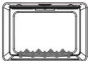
natural_image
Simple line drawing of a rectangular frame with a central rectangular area and triangular supports at the bottom (no text or symbols)Warm
-
Press WARM/PROOF, and then press WARM on the menu screen. "WARM" and 140°F (60°C) will be displayed.
-
Press START, if you wish to Warm food at 140°F (60°C).
OR
Enter the desired temperature by pressing the number keypad, and then press START. The temperature can be set from 140^ F ( 60^ C) to 210^ F ( 99^ C).
- "WARM" will appear in the display, once Start is pressed.
NOTE: After selecting an Oven Mode and Temperature, you have the option to set a Cook Time before pressing START.
-
Place food in the oven and close the door.
-
Press CANCEL when finished, and remove food from the oven.
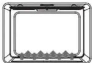
natural_image
Simple line drawing of a rectangular frame with a grid pattern at the bottom (no text or symbols)Proof
Before proofing, place the dough in a lightly greased bowl and cover loosely with wax paper, coated with shortening.
-
Place on second rack from the bottom and close the oven door.
-
Press WARM/PROOF, and then hold for 3 seconds. "PROOF" and 100^ (38°C) will be displayed.
-
Press START, if you wish to Proof dough at 100°F (38°C).
OR
Enter the desired temperature by pressing the number keypad, and then press START. The temperature can be set from 80^ (27°C) to 120^ (49°C).
- "PROOF" will appear in the display, once Start is pressed.
NOTE: After selecting an Oven Mode and Temperature, you have the option to set a Cook Time before pressing START.
-
Let the dough rise until nearly doubled in size, checking after 20-25 minutes. Proofing time may vary depending on dough type and quantity.
-
Press CANCEL when finished.
-
Before second proofing, shape the dough, place it in baking pan(s) and cover loosely with plastic wrap, coated with cooking spray. Follow the same placement and control steps above. Before baking, remove the plastic wrap.
RANGE CARE
CLEANING
IMPORTANT: Before cleaning, make sure all controls are off and the oven and cooktop are cool. Always follow label instructions on cleaning products. Soap, water and a soft cloth or sponge are suggested first unless otherwise noted. Do not use abrasive cleaning products.
EXTERIOR PORCELAIN ENAMEL SURFACES
Food spills containing acids, such as vinegar and tomato, should be cleaned as soon as the entire appliance is cool. These spills may affect the finish.
Cleaning Method:
Glass cleaner, mild liquid cleaner or nonabrasive scrubbing pad: Gently clean around the model and serial number plate because scrubbing may remove numbers.
EXTERIOR STAINLESS STEEL
NOTE: Do not use soap-filled scouring pads, abrasive cleaners, Cooktop Polishing Cream, steel-wool pads, gritty washcloths or some paper towels. Damage may occur, even with one-time or limited use.
Rub in direction of grain to avoid damaging.
Cleaning Methods:
Liquid detergent or all-purpose cleaner: Rinse well with clean water and dry with soft, lint-free cloth.
Stainless Steel Cleaner and Polish. Vinegar for hard water spots.
OVEN DOOR EXTERIOR
Cleaning Method:
Glass cleaner and paper towels or nonabrasive plastic scrubbing pad: Apply glass cleaner to soft cloth or sponge, not directly on panel.
PORCELAIN-COATED GRATES AND CAPS
- Clean as soon as cooktop, grates and caps are cool.
- Food spills containing acids, such as vinegar and tomato, should be cleaned as soon as the cooktop grates and caps are cool. These spills may affect the finish.
- To avoid chipping, do not bang grates and caps against each other or hard surfaces such as cast iron cookware.
• Do not reassemble caps on burners while wet.
Cleaning Method:
Nonabrasive plastic scrubbing pad and mildly abrasive cleanser.
BURNER SPREADER
Wash the burner spreader frequently with boiling water and detergent to remove any deposits which could block the flame outlet.
Before reinstalling, dry the burner spreader thoroughly so the burner will ignite properly.
COOKTOP CONTROL KNOBS
• Pull knobs straight away from control panel to remove.
- When replacing knobs, make sure knobs are in the Off position.
Cleaning Method:
Soap and water or dishwasher:
NOTE: Do not use steel wool, abrasive cleansers or oven cleaner. Do not soak knobs.
CONTROL PANEL
Cleaning Method:
Glass cleaner and soft cloth or sponge: Apply glass cleaner to soft cloth or sponge, not directly on panel.
NOTE: Do not use abrasive cleaners, steel-wool pads, gritty washcloths or some paper towels. Damage may occur.
OVEN CAVITY
Food spills should be cleaned when oven cools. At high temperatures, foods react with porcelain, so staining, etching, pitting or faint white spots can result.
Cleaning Method:
Mild detergent and warm water.
NOTE: Do not use oven cleaners.
OVEN RACKS AND ROASTING RACKS
Cleaning Method:
Steel-wool pad
OVEN DOOR REMOVAL
For normal oven use, there is no need to remove the oven door. However, should it become necessary to remove the door, follow the instructions in this section.
IMPORTANT:
• Make sure oven is cool and power to the oven has been turned off before removing the door.
- The oven door is heavy and fragile, and the door front is glass. To avoid oven door glass breakage, use both hands, and grasp only the sides of the oven door to remove.
- Be sure that both levers are securely in place before removing the door.
• Do not force door open or closed.
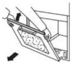
To remove the oven door:
- Open the oven door completely.
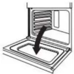
natural_image
Diagram of a microwave oven with a downward arrow indicating cooling or ventilation (no text or symbols)- Lift up the hinge latch on each side.
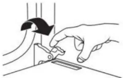
natural_image
Illustration of hands operating a mechanical device with a curved arrow indicating motion (no text or symbols)-
Close the oven door as far as it will shut.
-
While grasping both outside edges of the oven door, lift up on the door.
-
Continue to push the top of the door closed, while pulling the bottom of the door out of the hinge receivers in the door frame.
natural_image
Illustration of a hand using a tool to adjust or install a component, with no visible text or symbols.To replace the oven door:
- Insert both hanger arms into the hinge receivers in the door frame.
- Slowly open the oven door, and you will feel the door set into place.
- Move the hinge latches back into the locked position.
- Check that the door opens and closes freely. If it does not, repeat the door removal and replacement procedures.
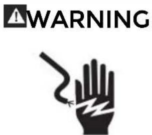
Electrical Shock Hazard
Make sure the oven and lights are cool and power to the oven has been turned off before replacing the light bulb(s).
The lenses must be in place when using the oven. The lenses serve to protect the light bulb from breaking.
The lenses are made of glass. Handle carefully to avoid breakage.
Failure to do so could result in death, electric shock, cuts or burns.
The oven light is a standard 25 watt (G9) appliance bulb.
IMPORTANT: Before replacing the bulb, make sure the oven is cool and the controls are turned off.
WARNING:
- Make sure the oven and lights are cool and power to the oven has been turned off before replacing the light bulb(s).
- The lenses must be in place when using the oven. The lenses serve to protect the light bulb from breaking.
- The lenses are made of glass. Handle carefully to avoid breakage.
- Failure to do so could result in death, electric shock, cuts or burns.
REPLACING AN OVEN LIGHT
The oven light is a standard 25-watt (G9) appliance bulb.
IMPORTANT: Before replacing the bulb, make sure the oven is cool and the controls are turned off.
- Disconnect the power.
- Remove the bulb cover by turning it anti-clockwise.
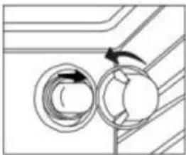
natural_image
Pure diagram of two circular components with directional arrows, no text or symbols present- Remove the burned-out bulb from the socket.
NOTE: To avoid damage or decreasing the life of the new bulb, do not touch the bulb with bare fingers. Wear gloves or use a tissue when replacing the light bulb.
- Replace the bulb, and then replace the bulb cover.
- Reconnect the power.
TROUBLESHOOTING
First try the solutions suggested here to possibly avoid the cost of a service call.
BAKING PROBLEMS
With any oven setting poor results can occur for many reasons other than a malfunction of the oven. Check the chart below for causes of the most common problems. Since the size, shape and material of baking utensils directly affect the baking results, the best solution may be to replace old baking utensils that have darkened and warped with age and use.
| PROBLEM | CAUSE |
| Food browns unevenly | Oven not preheatedAluminum foil on oven rack or oven bottomBaking utensil too large for recipePans touching each other or oven walls |
| Food too brown on bottom | Oven not preheatedUsing glass, dull or darkened metal pansIncorrect rack positionPans touching each other or oven walls |
| Food is dry or has shrunk excessively | Oven temperature too highBaking time too longOven door opened frequentlyPan size too large |
| Food is baking or roasting too slowly | Oven temperature too lowOven not preheatedOven door opened frequentlyTightly sealed with aluminum foilPan size too small |
| Pie crusts do not brown on bottom or crust is soggy | Baking time not long enoughUsing shiny steel pansIncorrect rack positionOven temperature is too low |
| Cakes pale, flat and may not be done inside | Oven temperature too lowIncorrect baking timeCake tested too soonOven door opened too oftenPan size may be too large |
| Cakes high in middle with crack on top | Oven temperature too highBaking time too longPans touching each other or oven wallsIncorrect rack positionPan size too small |
| Piecrust edges too brown | Oven temperature too highEdges of crust too thin |
COOKTOP PROBLEMS
| PROBLEM | POSSIBLE CAUSE | SOLUTION |
| Burner will not ignite | There is no power to the range. | Check that range is properly connected to 120V power supply. |
| Burner will not operate | First time use. Air still in the gas line. | Turn on any one of the surface burner knobs to release air from the gas lines. |
| Control knob is not set correctly. | Push in knob before turning to a setting. | |
| The burner port is clogged. | Clean burner port opening using a stiff, nylon toothbrush or a straightened paper clip. | |
| Burner Flames are uneven, yellow and/or noisy | Burner port(s) are clogged. | Clean burner port opening using a stiff, nylon toothbrush or a straightened paper clip. |
| Burner caps are not positioned properly. | Place burner caps so that the alignment pins are properly aligned with the slots. | |
| Propane gas is being used. | The range should be converted to LP gas by a qualified technician. | |
| Burner flame is too high or too low | Cooktop gas supply is not correct. | Ensure the range is set for the correct gas type. It is factory set for natural gas. If connecting to LP gas, the burners should be converted to LP gas with the orifice kit supplied and the pressure regulator converted to the LP gas setting by a qualified technician. |
| The gas pressure is not correct. | Make sure the pressure regulator is installed correctly and the gas line pressure is correct. See Installation Instructions. | |
| Burner makes popping noises | The burner is wet. | Allow the burner to dry before using. |
| The burner cap or gas spreader is not positioned correctly. | Place burner caps so that the alignment pins are properly aligned with the slots. | |
| Excessive heat around cookware on cooktop | The cookware is not the proper size for the burner. | Use cookware with a bottom surface approximately the same size as the cooking area and burner. Cookware should not extend more than 1" (2.5 cm) outside the cooking area. Adjust the flame so that it does not come up around the cookware. |
| Cooking results are not what expected | Using incorrect Cookware. | See the "Cookware" section. |
| The control knob is not set to the proper heat level. | See the "Controls" section. |
OVEN PROBLEMS
| PROBLEM | POSSIBLE CAUSE | SOLUTION |
| Oven is not heating | No power to the range. | Check the circuit breaker or fuse box to your house. Make sure there is proper electrical power to the oven. |
| Oven control not turned on. | Make sure the oven temperature has been selected. | |
| Oven is not cooking evenly | Not using the correct bake ware or oven rack position. | Refer to cook charts for recommended rack position. Always reduce recipe temperature by 25 °F (15 °C) when baking with Convention Bake mode. |
| Oven display stays Off | Power interruption. | Turn off power at the main power supply (fuse or breaker box). Turn breaker back on. If condition persists, call for service. |
| Cooling fan continues to run after oven is turned off | The electronic components have not yet cooled sufficiently. | The fan will turn off automatically when the electronic components have cooled sufficiently. |
| Oven light is not working properly | Light bulb loose or burned-out. | Reinsert or replace the light bulb. Touching the bulb with fingers may cause the bulb to burn out. |
| Oven light stays on | Door is not closing completely | Check for obstruction in oven door. Check to see if hinge is bent or door switch broken. |
| Cannot remove lens cover | Soil build-up around the lens cover. | Wipe lens cover area with a clean, dry towel prior to attempting to remove the lens cover. |
| Clock and timer are not working properly | No power to the range. | Check the circuit breaker or fuse box to your house. Make sure there is proper electrical power to the oven. |
| Excessive Moisture | When using bake mode, preheat the oven first. Convection Bake and Convection Roast will eliminate any moisture in the oven. | |
| Porcelain Chips | Porcelain interior is chipped by oven racks | When removing and replacing oven racks, always tilt racks upward and do not force them to avoid chipping the porcelain. |
Installation Requirements
TOOLS AND PARTS
Gather the required tools and parts before starting installation. Read and follow the instructions provided with any tools listed here.
Tools Needed
- Tape measure
- Flat-blade screwdriver
• Phillips screwdriver - Level
- Drill
- Wrench or pliers
- Pipe wrench
• 15/16" (2.4 cm) combination wrench - 1/8" (3.2 mm) drill bit (for wood floors)
- Marker or pencil
- Pipe-joint compound resistant to Propane gas
- 3/16" (4.8 mm) carbide-tipped masonry drill bit (for concrete/ceramic floors)
• Noncorrosive leak-detection solution
Parts Supplied
 | 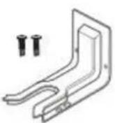 |
| Backsplash with screws | Anti-tip bracket with screws |
 | 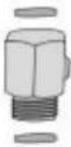 |
| Gas pressure regulator | Gas pipe adapter with washers |
Parts Needed
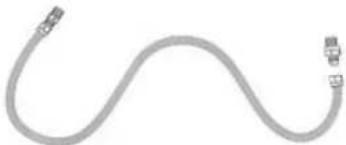
natural_image
Pure diagram of a flexible cable with two connectors (no text or symbols)Gas supply line kit
(supply line and 2 adapters)
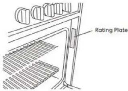
LOCATION REQUIREMENTS
IMPORTANT: Observe all governing codes and ordinances. Do not obstruct flow of combustion and ventilation air.
- It is the installer's responsibility to comply with installation clearances specified on the model/serial rating plate. The model/serial rating plate is located behind the oven door on the oven frame.
• The range should be located for convenient use in the kitchen.
- Recessed installations must provide complete enclosure of the sides and rear of the range.
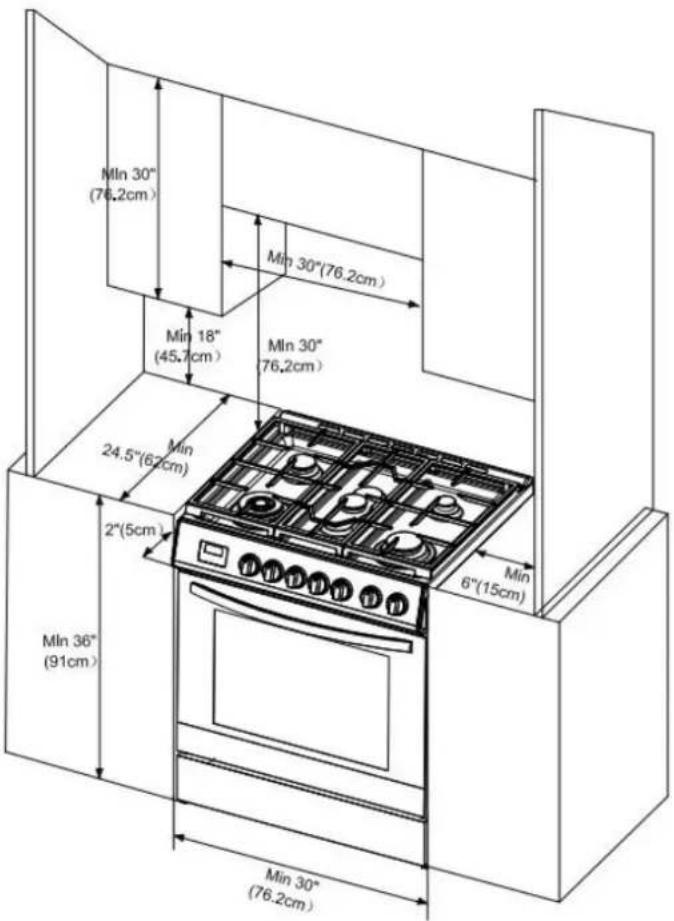
- To eliminate the risk of burns or fire by reaching over heated surface units, cabinet storage space located above the surface units should be avoided. If cabinet storage is to be provided, the risk can be reduced by installing a range hood or microwave hood combination that projects horizontally a minimum of 5" (12.7 cm) beyond the bottom of the cabinets.
• All openings in the wall or floor where range is to be installed must be sealed.
• Do not seal the range to the side cabinets.
• Cabinet opening dimensions that are shown must be used.
• Grounded electrical supply is required. See "Electrical Requirements" section.
- Proper gas supply connection must be available. See "Gas Supply Requirements" section.
- Contact a qualified floor covering installer to check that the floor covering can withstand at least 200^ (93°C).
- Use an insulated pad or 1/4" (0.64 cm) plywood under range if installing range over carpeting.
PRODUCT DIMENSIONS
This manual covers several models. Your model may appear different from the models depicted. Dimensions given are maximum dimensions across all models.
CLEARANCES
IMPORTANT: Some cabinet and building materials are not designed to withstand the heat produced by the oven for baking and self-cleaning. Check with your builder or cabinet supplier to make sure that the materials used will not discolor, delaminate or sustain other damage.
GIVEN DIMENSIONS ARE MINIMUM CLEARANCES.
Power Supply Location
IMPORTANT: An electrical outlet in the floor, may be either recessed or surface mounted, but an electrical outlet in the wall must be recessed to make the connection. For Direct Wiring, the electrical box should be mounted to the wall.
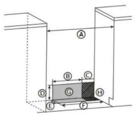
A 30" (76 cm)
B 11 ^1/2 " (29.2 cm)
C 6" (15.2 cm)
D 7 ^1/4 " (18.4 cm)
E 3" (7.6 cm)
F 17 ^1/2 " (44 cm)
G Recommended Location for Electrical Outlet
H Recommended Location for Gas Supply Connection
VENTING REQUIREMENTS
IMPORTANT: This range must be exhausted outdoors unless you are using ductless venting. Observe all governing codes and ordinances. Do not obstruct flow of combustion and ventilation air.
- Do not terminate the vent system in an attic or other enclosed area.
- Use an approved vent cap for proper performance. If an alternate wall or roof cap is used, be certain the cap size is not reduced and that it has a backdraft damper.
- Vent system must terminate to the outside unless you are using a ductless vent kit.
- Rigid metal vent is recommended. For best performance, do not use plastic or metal foil vent.
• If a joist or stud must be cut, then a supporting frame must be constructed.
• The size of the vent should be uniform.
• The vent system must have a damper.
• Seal all joints in the vent system.
• Use caulking to seal exterior wall or roof opening around the cap.
• Determine which venting method is best for your application.
Makeup Air
Local building codes may require the use of makeup air systems when using ventilation systems greater than specified CFM of air movement. The specified CFM varies from locale to locale. Consult your HVAC professional for specific requirements in your area.
ELECTRICAL REQUIREMENTS
120V 60Hz
Electrical Shock Hazard
Electrically ground range.
Failure to do so can result in death, fire or electrical shock.
Electrical Grounding Instructions
This appliance is equipped with a three-prong grounding plug for your protection against shock hazard and should be plugged directly into a properly grounded receptacle. Do not cut or remove the grounding prong from this plug.
This range is equipped with an electronic ignition system that will not operate if plugged into an outlet that is not properly polarized.
If codes permit and a separate ground wire is used, it is recommended that a qualified electrical installer determine that the ground path is adequate and wire gauge is in accordance with local codes.
Do not use an extension cord.
WARNING: Improper connection of the equipment-grounding conductor can result in a risk of electric shock. Check with a qualified electrician or service technician if you are in doubt as to whether the appliance is properly grounded. Do not modify the power supply cord plug. If it will not fit the outlet, have a proper outlet installed by a qualified electrician.
ELECTRICAL REQUIREMENTS - U.S.A. ONLY
Be sure that the electrical connection and wire size are adequate and in conformance with the National Electrical Code, ANSI/ NFPA No. 70-latest edition and all local codes and ordinances.
A copy of the above code standards can be obtained from:
National Fire Protection Association
1 Batterymarch Park
Quincy, MA 02169
Electrical Connection
- Check local codes and consult gas supplier. Check existing electrical supply and gas supply. It is recommended that all electrical connections be made by a licensed, qualified electrical installer.
- Range must be connected to the proper electrical voltage and frequency as specified on the model/serial rating plate. The plate is located behind the oven door on the oven frame. Refer to the illustrations in the "Location Requirements" section.
- A 120 volt, 60 Hz, AC only, 15-amp fused, electrical circuit is required. A time-delay fuse or circuit breaker is also recommended. It is recommended that a separate circuit serving only this range be provided.
- Electronic ignition systems operate within wide voltage limits, but proper grounding and polarity are necessary. Check that the outlet provides 120- volt power and is correctly grounded.
- This gas range is not required to be plugged into a GFCI (Ground-Fault Circuit Interrupter) outlet. It is recommended that you not plug an electric spark ignition gas range or any other major appliance into a GFCI wall outlet as it may cause the GFCI to trip during normal cycling.
- Performance of this range will not be affected if operated on a GFCI-protected circuit. However, occasional nuisance tripping of the GFCI breaker is possible due to the normal operating nature of electronic gas ranges.
• The wiring diagram is located on the back of the range in a clear plastic bag.
NOTE: The metal chassis of the range must be grounded in order for the control panel to work. If the metal chassis of the range is not grounded, no keypads will operate. Check with a qualified electrician if you are in doubt as to whether the metal chassis of the range is grounded.
ELECTRICAL REQUIREMENTS - CANADA ONLY
Be sure that the electrical connection and wire size are adequate and in conformance with the CSA Standard C22.1, Canadian Electrical Code, Part 1 - latest edition and all local codes and ordinances.
A copy of the above code standards can be obtained from:
Canadian Standards Association
178 Rexdale Blvd.
Toronto, ON M9W 1R3 CANADA
Electrical Connection
Check local codes and consult gas supplier. Check existing electrical supply and gas supply. It is recommended that all electrical connections be made by a licensed, qualified electrical installer.
- Check with a qualified electrical installer if you are not sure the range is properly grounded.
• A time-delay fuse or circuit breaker is recommended. - This range is equipped with a CSA International Certified Power Cord intended to be plugged into a standard 14-50R wall receptacle. Be sure the wall receptacle is within reach of range's final location.
• Do not use an extension cord.
• The wiring diagram is located on the back of the range in a clear plastic bag.
NOTE: The metal chassis of the range must be grounded in order for the control panel to work. If the metal chassis of the range is not grounded, no keypads will operate. Check with a qualified electrician if you are in doubt as to whether the metal chassis of the range is grounded.
GAS SUPPLY REQUIREMENTS
WARNING
Explosion Hazard
Use a new CSA International approved gas supply line.
Install a shut-off valve.
Securely tighten all gas connections.
If connected to LP, have a qualified person make sure gas pressure does not exceed 14" (36 cm) water column.
Examples of a qualified person include:
- licensed heating personnel
• authorized gas company personnel
• authorized service personnel
Failure to do so can result in death, explosion or fire.
Observe all governing codes and ordinances.
IMPORTANT: This installation must conform with all local codes and ordinances. In the absence of local codes, installation must conform with American National Standard, National Fuel Gas Code ANSI Z223.1 - latest edition or CAN/CGA B149 - latest edition.
IMPORTANT: Leak testing of the range must be conducted according to the manufacturer's instructions.
TYPE OF GAS
Natural Gas:
This range is design-certified by CSA International for use with natural gas or, after proper conversion, for use with LP gas.
- This range is factory-set for use with Natural gas. The model/serial rating plate located on the right side oven door trim has information on the types of gas that can be used. If the types of gas listed do not include the type of gas available, check with the local gas supplier.
LP Gas Conversion:
Conversion must be performed by a qualified service technician. The qualified agency performing this work assumes the gas conversion responsibility.
No attempt shall be made to convert the appliance from the gas specified on the model/serial rating plate for use with a different gas without consulting the serving gas supplier. See "GAS CONVERSION" section.
GAS SUPPLY LINE
Provide a gas supply line of 3/4" (1.9 cm) rigid pipe to the range location. A smaller size pipe on longer runs may result in insufficient gas supply. Pipe-joint compounds that resist the action of LP gas must be used. With LP gas, piping or tubing size can be 1/2" (1.3 cm) minimum. Usually, LP gas suppliers determine the size and materials used in the system.
Flexible metal appliance connector:
- If local codes permit, a new CSA design-certified, 4 - 5 ft (122 - 152.4 cm) long, 1/2" (1.3 cm) or 3/4" (1.9 cm) I.D., flexible metal appliance connector may be used for connecting range to the gas supply line.

natural_image
Schematic illustration of a black flexible hose with two connectors (no text or symbols)- A 1/2" (1.3 cm) male pipe thread is needed for connection to the female pipe threads of the inlet to the appliance pressure regulator.
- Do not kink or damage the flexible metal tubing when moving the range.
Rigid pipe connection:
The rigid pipe connection requires a combination of pipe fittings to obtain an in-line connection to the range. The rigid pipe must be level with the range connection. All strains must be removed from the supply and fuel lines so range will be level and in line.
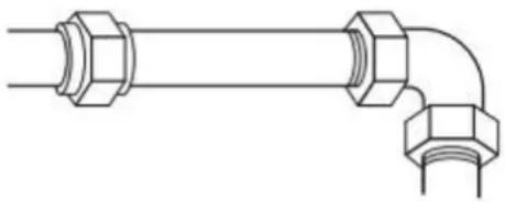
natural_image
Pure technical line drawing of a pipe fitting with hexagonal connectors (no text or symbols)Gas shutoff valve:
A manual gas line shut-off valve must be installed in an easily accessible location. Do not block access to shut-off valve. The valve is for turning on or shutting off gas to the range.
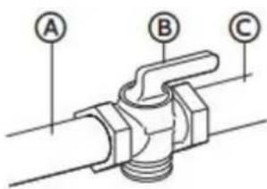 | A Gas Supply LineB Shutoff Valve "Open" PositionC To Range |
The gas pressure regulator supplied with this range must be used. The inlet pressure to the regulator should be as follows for proper operation:
| Natural gas | LP gas | |
| Minimum pressure | 4" WCP | 10" WCP |
| Maximum pressure | 7" WCP | 11" WCP |
Contact local gas supplier if you are not sure about the inlet pressure.
Burner Input Requirements
Input ratings shown on the model/serial rating plate are for elevations up to 2,000 ft (609.6 m).
For elevations above 2,000 ft (609.6 m), ratings are reduced at a rate of 4% for each 1,000 ft (304.8 m) above sea level (not applicable for Canada).
GAS SUPPLY PRESSURE TESTING
Gas supply pressure for testing regulator must be at least 1" (2.5 cm) water column pressure above the manifold pressure shown on the model/serial rating plate.
Line pressure testing above 0.5 psi gauge (14" WCP)
The range and its individual shutoff valve must be disconnected from the gas supply piping system during any pressure testing of that system at test pressures in excess of 0.5 psi (3.5 kPa).
Line pressure testing at 0.5 psi gauge (14" WCP) or lower
The range must be isolated from the gas supply piping system by closing its individual manual shutoff valve during any pressure testing of the gas supply piping system at test pressures equal to or less than 1/2 psi (3.5 kPa).
Installation Instructions
IMPORTANT: This appliance shall be installed only by authorized persons and in accordance with the manufacturer's installation instructions, local gas fitting regulations, municipal building codes, electrical wiring regulations, local water supply regulations.
UNPACK RANGE

WARNING
Excessive Weight Hazard
Use two or more people to move and install range.
Failure to do so can result in back or other injury.
- Remove shipping materials, tape and film from the range. Keep cardboard bottom under range. Do not dispose of anything until the installation is complete.
- Remove oven racks and parts package from oven and shipping materials.
- To remove cardboard bottom, first take 4 cardboard corners from the carton. Stack one cardboard corner on top of another. Repeat with the other 2 corners. Place them lengthwise on the floor behind the range to support the range when it is laid on its back.
- Using two or more people, firmly grasp the range and gently lay it on its back on the cardboard corners.
- Remove cardboard bottom.
NOTES:
• The leveling legs can be adjusted while the range is on its back.
- To place range back up into a standing position, put a sheet of cardboard or hardboard on the floor in front of range to protect the flooring. Using two or more people, stand range back up onto the cardboard or hardboard.
INSTALL ANTI-TIP DEVICE
WARNING
Tip Over Hazard
• A child or adult can tip the range and be killed.
• Install anti-tip bracket to floor or wall per installation instructions.
- Slide range back so rear range foot is engaged in the slow of the anti top bracket.
• Re-engage the anti-tip bracket if range is moved.
- Do not operate the range without anti-tip bracket installed and engaged.
- Failure to follow these instructions can result in death or serious burns to children and adults.
IMPORTANT:
- An anti-tip bracket is provided with the range. The anti-tip bracket uses a rear range foot to secure the range to the floor or wall.
-
Attach the anti-tip bracket to the floor or wall so that the rear range foot will be centered within the bracket when the range is pushed into its final position.
-
Remove the anti-tip bracket and screws from the parts bag.
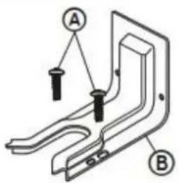
A 16 x 1 ^5 / _8 " Screws (2)
B Anti-tip Bracket
NOTE: The anti-tip bracket must be securely mounted to the subfloor or wall. The flooring's thickness may require longer screws to anchor bracket to subfloor.
- Place the bracket so that the back of the bracket is against the rear wall and the side edge of the bracket is 3/8" to 1/2" from the adjacent cabinet.
NOTE: If there is no adjacent cabinet, place the bracket so that the edge of the bracket is 3/8" to 1/2" in from the range side panel. If the countertop overhangs the cabinet, offset the bracket from the cabinet by the depth of the overhang plus an additional 3/8" to 1/2".
- Using the anti-tip bracket as a template, mark the two holes for either a Floor Wood, Floor Concrete, or Wall installation, as shown.
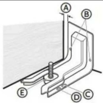
A Distance from Adjacent Cabinet (3/8" to 1/2" [0.95 cm to 1.27 cm])
B Wall Holes
C Concrete Floor Holes
D Wood Floor Holes
E Rear Range Foot
- Drill two pilot holes where marked. Follow the instructions specific to your construction.
NOTE: A nail or awl may be used to create a pilot hole, if a drill is not available. For concrete construction 1/4" x 1 1/2" Lag Bolts and 1/2" O.D. Sleeve Anchors are required.
Wood
• Floor - Drill a 1/8" pilot hole, as shown.
NOTE: Contact a qualified floor covering installer for the best procedure for drilling mounting holes through your type of floor covering.
• Wall - Drill an angled 1/8" pilot hole, as shown.
Concrete
- Drill the size hole recommended for the anchors into the concrete at the center of the holes identified as Floor Concrete or Wall.
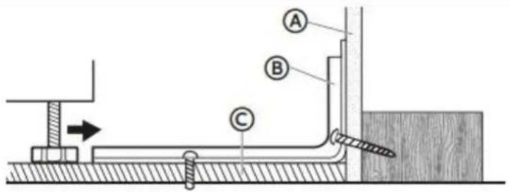
A Wall
B Anti-tip Bracket
C Floor
5. Install the anti-tip bracket.
Wood
• Using the two screws (provided) fasten the anti-tip bracket to the floor or wall.
NOTE: The screw must enter wood or metal.
Concrete
- Insert the sleeve anchor into the drilled holes and then insert the lag bolts through the anti-tip bracket and into the floor or wall. The bolts must be properly tightened as recommended for the hardware.
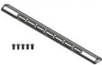
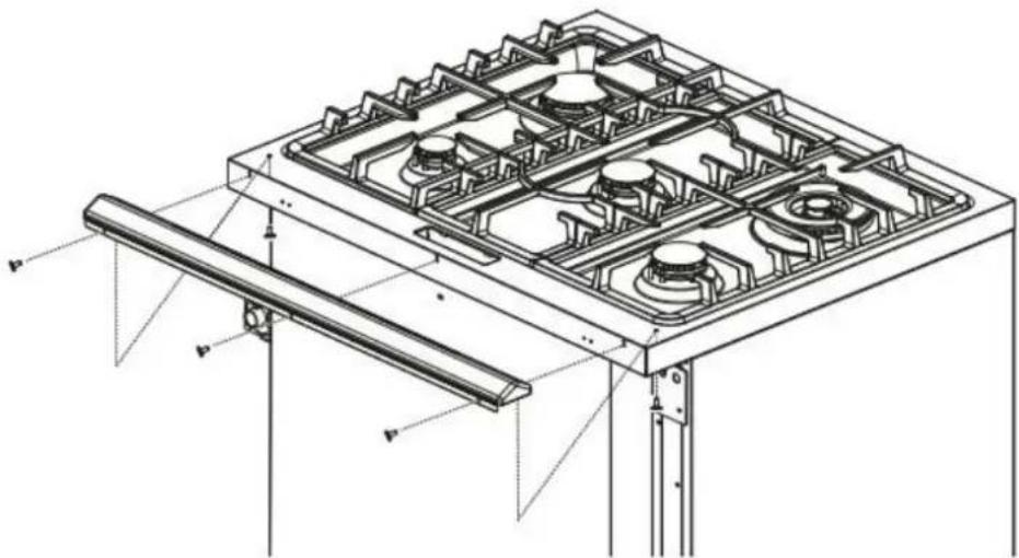
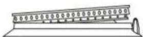
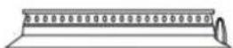
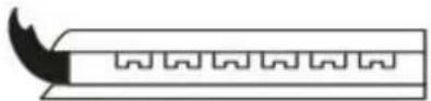
INSTALL BACKSPLASH
• Install the backsplash to rear of range with the screws provided.
natural_image
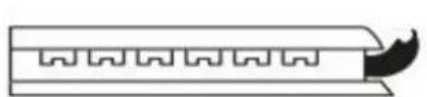
Technical line drawing of a gas stove frame structure with mounting brackets and structural supports (no text or symbols)GAS CONNECTION
WARNING
Explosion Hazard
Use a new CSA International approved gas supply line.
Install a shut-off valve.
Securely tighten all gas connections.
If connected to LP, have a qualified person make sure gas pressure does not exceed 14" (36 cm) water column.
Examples of a qualified person include:
- licensed heating personnel
• authorized gas company personnel
• authorized service personnel
Failure to do so can result in death, explosion or fire.
This appliance shall be installed only by authorized persons and in accordance with the manufacturer's installation instructions, local gas fitting regulations, municipal building codes, electrical wiring regulations, local water supply regulations.
This range is factory-set for use with Natural gas. To use this range with Propane gas, see the "GAS CONVERSION section before connecting this range to the gas supply. Gas conversions from Natural gas to Propane gas or from Propane gas to Natural gas must be done by a qualified installer.
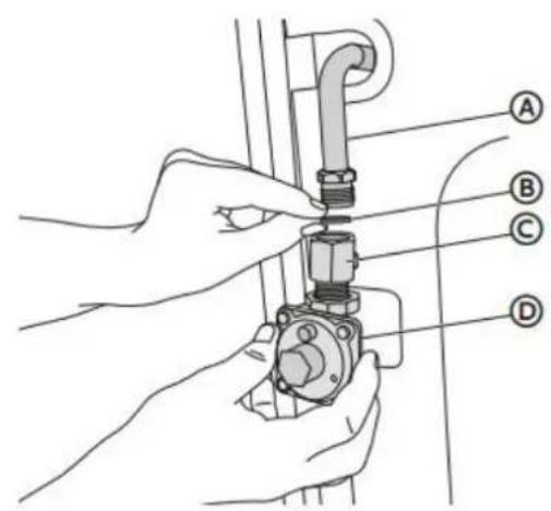
TYPICAL FLEXIBLE CONNECTION
-
Apply pipe-joint compound made for use with LP gas to the smaller thread ends of the flexible connector adapters.
-
Attach one adapter to the gas pressure regulator and the other adapter to the gas shutoff valve. Tighten both adapters, being certain not to move or turn the gas pressure regulator.
 | A Adapter (provided)B Gas Pressure RegulatorC Gas Supply LineD Adapters (From Gas Supply Line Kit)E Gas Shutoff Valve |
- Use a 15/16" (2.4 cm) combination wrench and channel lock pliers to attach the flexible connector to the adapters. Check that connector is not kinked.
TYPICAL RIGID PIPE CONNECTION
A combination of pipe fittings must be used to connect the range to the existing gas line. Your connections may be different, according to the supply line type, size and location.
- Apply pipe-joint compound made for use with LP gas to all pipe thread connections.
- Using a pipe wrench to tighten, connect the gas supply to the range.
 | A Gas Line from RangeB Washer (provided)C Adapter (provided)D Gas Pressure Regulator (provided) |
CONVERT TO LP GAS (OPTIONAL)
This range is shipped from the factory set up to use natural gas. It can be converted to use LP gas by a qualified service technician.
The LP conversion kit is sold separately. The conversion to LP requires all surface burner orifices and, if applicable, gas oven orifices to be changed. In addition, the nozzle on the gas pressure regulator needs to be reversed.
See "GAS CONVERSION" section for detailed instructions.
NOTE: All replaced orifices must be left with the consumer, including the instructions and retrofit sizes and orifice indication.
COMPLETE CONNECTION
Electrical Shock Hazard
Disconnect power before servicing.
Plug into a grounded 3-prong outlet.
Do not use an adapter or an extension cord.
Failure to do so can result in death, fire, or electrical shock
- Open the manual shutoff valve in the gas supply line. The valve is open when the handle is parallel to the gas pipe.
- Test all connections by brushing on an approved noncorrosive leak-detection solution. If bubbles appear, a leak is indicated. Correct any leak found.
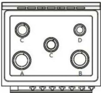
- Remove, if any, packaging tapes securing the burners on the surface. If the cooktop burner bases and caps are not pre-installed, remove them from package containing parts, align and place the burner bases and caps accordingly.
natural_image
Diagram of a control panel with six labeled circular components (A, B, C, D, and an unlabeled top panel), no text or symbols present.Note: Align notches in burner caps with pins in burner base. Burner caps should be level when properly positioned. If burner caps are not properly positioned, surface burners will not light.


Auxiliary Burner Semi Rapid Burner Rapid Burner
Incorrectly Positioned
Correctly Positioned
- Place burner grates over burners and caps.
- Plug in range or reconnect power.
ADJUST FLAME HEIGHT
Check and adjust the height of top burner flames. The cooktop "low" burner flame should be a steady blue flame approximately 1/4" (6 mm) high. Propane gas flames have a slightly yellow tip.
Low Flame
High Flame
If burners do not light properly:
- Turn burner control knob to the "OFF" position.
- Check that the range is plugged in. Check that the circuit breaker has not tripped or the household fuse has not blown.
- Check that the gas shutoff valves are set to the "open" position.
- Check that burner caps are properly positioned on burner bases.
To adjust standard burner:
IMPORTANT: Adjustments must be made with two other burners in operation on a medium setting. This prevents the upper row of flames from being set too low, resulting in the flame being extinguished when other burners are turned on.
The flame can be adjusted using the adjustment screw in the center of the valve stem. The valve stem is located directly behind the control knob.
- Light the burner and turn the knob to the lowest setting (MIN).
- Pull and remove the control knob.
-
Insert a small, flat-blade screwdriver into the adjustment screw, and slowly turn the screw until the flame appearance is correct.
-
Open the valve more if the flames are too small or fluttered.
- Close the valve more if the flames are too large.
A Adjustment Screw B Control Knob Stem
- Replace the control knob.
- Test and check the flame by turning the control knob from the lowest to the highest settings.
NOTE: For burners (on some models) with safety valve, make sure that the regulation obtained is sufficient to maintain heating of the thermocouple. If it is not, increase the minimum flame.
ABNORMAL OPERATION
ANY OF THE FOLLOWING ARE CONSIDERED TO BE ANBORMAL OPERATION AND MAY REQUIRE SERVICING:
- Yellow tipping of the hob burner flame
- Sooting up of cooking utensils.
- Burners not igniting properly.
- Burners failing to remain lit.
- Burners extinguished by oven door.
• Gas valves, which are difficult to turn.
IN CASE THE APPLIANCE FAILS TO OPERATE CORRECTLY, CONTACT THE AUTHORIZED SERVICE PROVIDE IN YOUR AREA.
THE BURNERS REQUIRE NO REGULATION OF THE PRIMARY AIR.
LEVEL RANGE
IMPORTANT: Do not operate the range if its rear foot is not completely engaged in the anti-tip bracket. Never completely remove the leveling legs or the range will not be secured to the anti-tip device properly.
- Slide range into final location, making sure rear leveling leg slides into the anti-tip bracket. Leave a 1" (2.5 cm) gap between the back of the range and the back wall.
- Check that the range is level by placing a level on the oven bottom. If needed, use a wrench to adjust the height of the leveling legs until the range is level from side to side and from front to back.
NOTE: The range must be level for optimum cooking and baking performance.
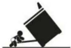
VERIFY ANTI-TIP BRACKET ENGAGEMENT
- Place the outside of your foot against the bottom of the front panel to keep the range from moving, and then grasp the back of the range, as shown.
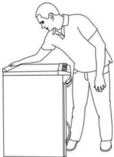
natural_image
Line drawing of a person leaning against the side of a refrigerator (no text or symbols)- Slowly attempt to tilt the range forward.
- If you encounter immediate resistance, the range foot is engaged in the anti-tip bracket. Range installation is completed.
- If the rear of the range lifts more than 1/2" (1.3 cm) off the floor without resistance, stop tilting the range and lower it gently back to the floor. The range foot is not engaged in the anti-tip bracket. Proceed to Steps 3 and 4.
IMPORTANT: If there is a snapping or popping sound when tilting the range, the range may not be fully engaged in the bracket. Check to see if there are obstructions keeping the range from sliding to the wall or keeping the range foot from sliding into the bracket. Verify that the bracket is held securely in place by the mounting screws.
-
Slide the range forward, and verify that the anti-tip bracket is securely attached to the floor or wall.
-
Slide range back so the rear range foot is inserted into the slot of the anti-tip bracket.
IMPORTANT: If the range is pulled away from the wall for any reason, always verify anti-tip bracket engagement again.
Kenmore®
For Customer Care go to:
www.kenmore.com/contact-us/
to select your local area or retailer where this appliance was purchased for contact information on scheduling in-home repair service or ordering replacement parts.

Transform SR Brands Management LLC
Hoffman Estates, IL, U.S.A. 60179 U.S.A
www.kenmore.com

REGISTRO DEL PRODUCTO
natural_image
Silhouette of a person pushing a large block on a horizontal line (no text or symbols)Peligro de vuelco
Ⓐ Tapa de la Hornilla
natural_image
Simple line drawing of a crossed-out electrical circuit with no text or symbolsLA LLAMA ES DEMASIA USE
GRANDE PARA EL TAMA
DE LA OLLA QUE
natural_image
Symbolic illustration of a fire with smoke and flames crossed out by a barrier (no text or labels)TAPADERAS AJUSTEN BIE
OLLA
DESBALANCEADA
natural_image
Pure technical diagram of a rectangular enclosure with internal components and mounting brackets (no text or symbols)natural_image
Simple line drawing of a rectangular enclosure with a grid pattern at the bottom (no text or symbols)natural_image
Diagram of a kitchen appliance with a downward arrow indicating a process or removal (no text or symbols present)natural_image
Illustration of hands using a tool to adjust or install a component, with no visible text or symbols.natural_image
Illustration of a hand using a tool to adjust or install a component, with no visible text or symbols.natural_image
Pure mechanical diagram showing two circular components with directional arrows, no text or symbols presentnatural_image
Pure diagram of a mechanical component with four small pins, no text or symbols presentnatural_image
Pure electrical circuit lines without any symbolsnatural_image
Technical line drawing of a rack-mounted heating element with cooling fins (no text or symbols)Placa de característic.
DIMENSIONES DEL PRODUCTO
ESPACIOS LIBRES
Ⓐ 30" (76 cm)
⑧ 11 ^1/2 " (29,2 cm)
© 6" (15,2 cm)
(D) 3" (18,4 cm)
⑤ 3" (7,6 cm)
⑤ 17 ^1/2 " (44 cm)
Toronto, ON M9W 1R3 CANADA
natural_image
Schematic illustration of a black flexible hose with connectors (no text or symbols)natural_image
Pure technical line drawing of a pipe fitting with hexagonal connectors (no text or symbols)Ⓐ Tornillos de 16 × 1^5/_8 " (2)
©Soporte antivuelco
Ⓐ Pared
B Soporte antivuelco
© Piso
natural_image
Technical line drawing of a gas stove or heating unit with multiple fans and mounting brackets (no text or symbols)CONEXIÓN DE GAS

ADVERTENCIA