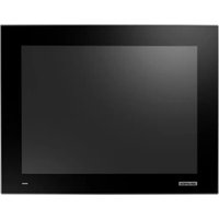
FPM-715W-P9AE - Monitor Advantech - Free user manual and instructions
Find the device manual for free FPM-715W-P9AE Advantech in PDF.


User questions about FPM-715W-P9AE Advantech
0 question about this device. Answer the ones you know or ask your own.
Ask a new question about this device
Download the instructions for your Monitor in PDF format for free! Find your manual FPM-715W-P9AE - Advantech and take your electronic device back in hand. On this page are published all the documents necessary for the use of your device. FPM-715W-P9AE by Advantech.
USER MANUAL FPM-715W-P9AE Advantech
natural_image
Illustration of three kitchen appliances in green outline style (no text or symbols)FPM-700/700W Series
15" XGA/17" SXGA/19" SXGA Industrial Monitors with Resistive Touch, Direct HDMI, DP, and VGA Ports
15.6"/21.5"/23.8" Full HD Industrial Monitor with PCAP Touch, Direct HDMI, DP, and VGA Ports
限用物質含有情況標示聲明書
Declaration of the Presence Condition of the Restricted Substances Marking
| 設備名稱:液晶顯示器 型號 (型式): FPM-715-R9AE, FPM-715W-P9AEEquipment name Type designation (Type): FPM-717-R9AE, FPM-719-R9AE | ||||||
| 單元Unit | 限用物質及其化學符號Restricted substances and its chemical symbols | |||||
| 鉛Lead(Pb) | 汞Mercury(Hg) | 鎘Cadmium(Cd) | 六價鉻Hexavalent chromium( Cr^+6 ) | 多溴聯苯Polybrominated biphenyls(PBB) | 多溴二苯醚Polybrominated diphenyl ethers(PBDE) | |
| 電路板- | ○ ○ ○ | ○ ○ | ||||
| 內外殼(外殼、內部框架...等) | ○ ○ | ○ ○ ○ | ○ | |||
| 其它固定組件(螺絲、夾具、卡榫) | - ○ | ○ ○ ○ | ○ | |||
| 配件(滑鼠、鍵盤、電源線、排線、傳輸線、網路線...等) | - ○ | ○ ○ ○ | ○ | |||
| 液晶面板- | ○ ○ | ○ ○ ○ | ||||
| 觸控模組- | ○ ○ | ○ ○ ○ | ||||
| 備考1.“超出0.1 wt %”及“出超0.01 wt %”係指限用物質之百分比含量超出百分比含量基準值。Note 1.“Exceeding 0.1 wt %” and “exceeding 0.01 wt %” indicate that the percentage content of the restricted substance exceeds the reference percentage value of presence condition.備考2.“○”係指該項限用物質之百分比含量未超出百分比含量基準值。Note 2.“○”indicates that the percentage content of the restricted substance does not exceed the percentage of reference value of presence.備考3.“-”係指該項限用物質為排除項目。Note 3.The “-” indicates that the restricted substance corresponds to the exemption. | ||||||
限用物質含有情況標示聲明書
Declaration of the Presence Condition of the Restricted Substances Marking
PLM MDR NO: MDR-007787
| 設備名稱:液晶顯示器 型號 (型式): FPM-721W-P9AEEquipment name Type designation (Type) | ||||||
| 單元Unit | 限用物質及其化學符號Restricted substances and its chemical symbols | |||||
| 鉛Lead(Pb) | 汞Mercury(Hg) | 鎘Cadmium(Cd) | 六價鉻Hexavalent chromium( Cr^+6 ) | 多溴聯苯Polybrominated biphenyls(PBB) | 多溴二苯醚Polybrominated diphenyl ethers(PBDE) | |
| 電路板 ○ | ○ ○ ○ | ○ | ||||
| 內外殼(外殼、內部框架 ...等) | ○ ○ | ○ ○ ○ | ○ | |||
| 觸控模組 - | ○ ○ | ○ ○ ○ | ||||
| 其它固定組件(螺絲、夾具、卡榫) | - ○ | ○ ○ ○ | ○ | |||
| 線材 - ○ | ○ ○ ○ | ○ | ||||
| 液晶面板 - | ○ ○ | ○ ○ ○ | ||||
| 備考 1. “超出 0.1 wt %”及“超出 0.01 wt %”係指限用物質之百分比含量超出百分比含量基準值。Note 1. “Exceeding 0.1 wt %” and “exceeding 0.01 wt %” indicate that the percentage content of the restricted substance exceeds the reference percentage value of presence condition.備考 2. “○”係指該項限用物質之百分比含量未超出百分比含量基準值。Note 2. “○”indicates that the percentage content of the restricted substance does not exceed the percentage of reference value of presence.備考 3. “-”係指該項限用物質為排除項目。Note 3. The “-” indicates that the restricted substance corresponds to the exemption. | ||||||
限用物質含有情況標示聲明書
Declaration of the Presence Condition of the Restricted Substances Marking
| 設備名稱:液晶顯示器 型號 (型式):FPM-724W-P9AEEquipment name Type designation (Type) | ||||||
| 單元Unit | 限用物質及其化學符號Restricted substances and its chemical symbols | |||||
| 鉛Lead(Pb) | 汞Mercury(Hg) | 鎘Cadmium(Cd) | 六價鉻Hexavalent chromium( Cr^+6 ) | 多溴聯苯Polybrominated biphenyls(PBB) | 多溴二苯醚Polybrominated diphenyl ethers(PBDE) | |
| 電路板 ○ | ○ ○ ○ | ○ | ||||
| 內外殼(外殼、內部框架...等) | ○ ○ | ○ ○ ○ | ○ | |||
| 其它固定組件(螺絲、夾具、卡榫) | - ○ | ○ ○ ○ | ○ | |||
| 線材 - ○ | ○ ○ ○ | ○ | ||||
| 液晶面板 - | ○ ○ | ○ ○ ○ | ||||
| 觸控模組 ○ | ○ ○ | ○ ○ ○ | ||||
| 備考1.“超出0.1 wt %”及“超出0.01 wt %”係指限用物質之百分比含量超出百分比含量基準值。Note 1.“Exceeding 0.1 wt %” and “exceeding 0.01 wt %” indicate that the percentage content of the restricted substance exceeds the reference percentage value of presence condition.備考2.“○”係指該項限用物質之百分比含量未超出百分比含量基準值。Note 2.“○”indicates that the percentage content of the restricted substance does not exceed the percentage of reference value of presence.備考3.“-”係指該項限用物質為排除項目。Note 3.The “-” indicates that the restricted substance corresponds to the exemption. | ||||||
Copyright
The documentation and the software included with this product are copyrighted 2024 by Advantech Co., Ltd. All rights are reserved. Advantech Co., Ltd. reserves the right to make improvements in the products described in this manual at any time without notice. No part of this manual may be reproduced, copied, translated, or transmitted in any form or by any means without the prior written permission of Advantech Co., Ltd. The information provided in this manual is intended to be accurate and reliable. However, Advantech Co., Ltd. assumes no responsibility for its use, nor for any infringements of the rights of third parties that may result from its use.
Acknowledgments
Intel® and Pentium® are trademarks of Intel Corporation.
Microsoft Windows are registered trademarks of Microsoft Corp.
All other product names or trademarks are properties of their respective owners.
This manual includes the following products:
FPM-715-R9AE
FPM715R9A2201-T, FPM715R9A2202-T, FPM715R9A2203-T, FPM715R9A2204-T, FPM715R9A2205-T, FPM715R9A2206-T, FPM715R9A2301-T, FPM715R9A2302-T, FPM715R9A2303-T, FPM715R9A2304-T, FPM715R9A2305-T, FPM715R9A2306-T, FPM715R9A2401-T, FPM715R9A2402-T, FPM715R9A2403-T, FPM715R9A2404-T, FPM715R9A2405-T, FPM715R9A2406-T, FPM715R9A2501-T, FPM715R9A2502-T, FPM715R9A2503-T, FPM715R9A2504-T, FPM715R9A2505-T, FPM715R9A2506-T, FPM715R9A2601-T, FPM715R9A2602-T, FPM715R9A2603-T, FPM715R9A2604-T, FPM715R9A2605-T, FPM715R9A2606-T, FPM715R9A2701-T, FPM715R9A2702-T, FPM715R9A2703-T, FPM715R9A2704-T, FPM715R9A2705-T, FPM715R9A2706-T,,
FPM-717-R9AE
FPM717R9A2201-T, FPM717R9A2202-T, FPM717R9A2203-T, FPM717R9A2204-T, FPM717R9A2205-T, FPM717R9A2206-T, FPM717R9A2301-T, FPM717R9A2302-T, FPM717R9A2303-T, FPM717R9A2304-T, FPM717R9A2305-T, FPM717R9A2306-T, FPM717R9A2401-T, FPM717R9A2402-T, FPM717R9A2403-T, FPM717R9A2404-T, FPM717R9A2405-T, FPM717R9A2406-T, FPM717R9A2501-T, FPM717R9A2502-T, FPM717R9A2503-T, FPM717R9A2504-T, FPM717R9A2505-T, FPM717R9A2506-T, FPM717R9A2601-T, FPM717R9A2602-T, FPM717R9A2603-T, FPM717R9A2604-T, FPM717R9A2605-T, FPM717R9A2606-T, FPM717R9A2701-T, FPM717R9A2702-T, FPM717R9A2703-T, FPM717R9A2704-T, FPM717R9A2705-T, FPM717R9A2706-T,
FPM-719-R9AE
FPM719R9A2201-T, FPM719R9A2202-T, FPM719R9A2203-T, FPM719R9A2204-T, FPM719R9A2205-T, FPM719R9A2206-T, FPM719R9A2301-T, FPM719R9A2302-T, FPM719R9A2303-T, FPM719R9A2304-T, FPM719R9A2305-T, FPM719R9A2306-T, FPM719R9A2401-T, FPM719R9A2402-T, FPM719R9A2403-T, FPM719R9A2404-T, FPM719R9A2405-T, FPM719R9A2406-T, FPM719R9A2501-T, FPM719R9A2502-T, FPM719R9A2503-T, FPM719R9A2504-T, FPM719R9A2505-T, FPM719R9A2506-T, FPM719R9A2601-T, FPM719R9A2602-T, FPM719R9A2603-T, FPM719R9A2604-T, FPM719R9A2605-T, FPM719R9A2606-T, FPM719R9A2701-T, FPM719R9A2702-T, FPM719R9A2703-T, FPM719R9A2704-T, FPM719R9A2705-T, FPM719R9A2706-T,
FPM-715W-P9AE
FPM715WP9A2201-T, FPM715WP9A2202-T, FPM715WP9A2203-T, FPM715WP9A2204-T, FPM715WP9A2205-T, FPM715WP9A2206-T, FPM715WP9A2301-T, FPM715WP9A2302-T, FPM715WP9A2303-T, FPM715WP9A2304-T, FPM715WP9A2305-T, FPM715WP9A2306-T, FPM715WP9A2401-T, FPM715WP9A2402-T, FPM715WP9A2403-T, FPM715WP9A2404-T, FPM715WP9A2405-T, FPM715WP9A2406-T, FPM715WP9A2501-T, FPM715WP9A2502-T, FPM715WP9A2503-T, FPM715WP9A2504-T, FPM715WP9A2505-T, FPM715WP9A2506-T, FPM715WP9A2601-T, FPM715WP9A2602-T, FPM715WP9A2603-T, FPM715WP9A2604-T, FPM715WP9A2605-T, FPM715WP9A2606-T, FPM715WP9A2701-T, FPM715WP9A2702-T, FPM715WP9A2703-T, FPM715WP9A2704-T, FPM715WP9A2705-T, FPM715WP9A2706-T
FPM-721W-P9AE
FPM721WP9A2401-T, FPM721WP9A2402-T, FPM721WP9A2403-T, FPM721WP9A2404-T, FPM721WP9A2405-T, FPM721WP9A2406-T, FPM721WP9A2501-T, FPM721WP9A2502-T, FPM721WP9A2503-T, FPM721WP9A2504-T, FPM721WP9A2505-T, FPM721WP9A2506-T, FPM721WP9A2601-T, FPM721WP9A2602-T, FPM721WP9A2603-T, FPM721WP9A2604-T, FPM721WP9A2605-T, FPM721WP9A2606-T, FPM721WP9A2701-T, FPM721WP9A2702-T, FPM721WP9A2703-T, FPM721WP9A2704-T, FPM721WP9A2705-T, FPM721WP9A2706-T, FPM721WP9A2801-T, FPM721WP9A2802-T, FPM721WP9A2803-T, FPM721WP9A2804-T, FPM721WP9A2805-T, FPM721WP9A2806-T, FPM721WP9A2901-T, FPM721WP9A2902-T, FPM721WP9A2903-T, FPM721WP9A2904-T, FPM721WP9A2905-T, FPM721WP9A2906-T,
Part No. 2004070002 Edition 3
Printed in China June 2024
FPM-724W-P9AE
FPM724WP9A2401-T, FPM724WP9A2402-T, FPM724WP9A2403-T, FPM724WP9A2404-T, FPM724WP9A2405-T, FPM724WP9A2406-T, FPM724WP9A2501-T, FPM724WP9A2502-T, FPM724WP9A2503-T, FPM724WP9A2504-T, FPM724WP9A2505-T, FPM724WP9A2506-T, FPM724WP9A2601-T, FPM724WP9A2602-T, FPM724WP9A2603-T, FPM724WP9A2604-T, FPM724WP9A2605-T, FPM724WP9A2606-T, FPM724WP9A2701-T, FPM724WP9A2702-T, FPM724WP9A2703-T, FPM724WP9A2704-T, FPM724WP9A2705-T, FPM724WP9A2706-T, FPM724WP9A2801-T, FPM724WP9A2802-T, FPM724WP9A2803-T, FPM724WP9A2804-T, FPM724WP9A2805-T, FPM724WP9A2806-T, FPM724WP9A2901-T, FPM724WP9A2902-T, FPM724WP9A2903-T, FPM724WP9A2904-T, FPM724WP9A2905-T, FPM724WP9A2906-T,
Product Warranty (2 years)
Advantech warrants the original purchaser that each of its products will be free from defects in materials and workmanship for two years from the date of purchase.
This warranty does not apply to any products that have been repaired or altered by persons other than repair personnel authorized by Advantech, or products that have been subject to misuse, abuse, accident, or improper installation. Advantech assumes no liability under the terms of this warranty as a consequence of such events.
Because of Advantech's high quality-control standards and rigorous testing, most customers never need to use our repair service. If an Advantech product is defective, it will be repaired or replaced free of charge during the warranty period. For out-of-warranty repairs, customers will be billed according to the cost of replacement materials, service time, and freight. Please consult your dealer for more details.
If you believe your product to be defective, follow the steps outlined below.
- Collect all the information about the problem encountered. (For example, CPU speed, Advantech products used, other hardware and software used, etc.) Note anything abnormal and list any onscreen messages displayed when the problem occurs.
- Call your dealer and describe the problem. Please have your manual, product, and any helpful information readily available.
- If your product is diagnosed as defective, obtain a return merchandise authorization (RMA) number from your dealer. This allows us to process your return more quickly.
- Carefully pack the defective product, a completed Repair and Replacement Order Card, and a proof of purchase date (such as a photocopy of your sales receipt) into a shippable container. Products returned without a proof of purchase date are not eligible for warranty service.
- Write the RMA number clearly on the outside of the package and ship the package prepaid to your dealer.
Declaration of Conformity
FCC Class A
This equipment has been tested and found to comply with the limits for a Class A digital device, pursuant to part 15 of the FCC Rules. These limits are designed to provide reasonable protection against harmful interference when the equipment is operated in a commercial environment. This equipment generates, uses, and can radiate radio frequency energy and, if not installed and used in accordance with the instruction manual, may cause harmful interference to radio communications. Operation of this equipment in a residential area is likely to cause harmful interference. In this event, users are required to correct the interference at their own expense.
Technical Support and Assistance
- Visit the Advantech website at www.advantech.com/support to obtain the latest product information.
- Contact your distributor, sales representative, or Advantech's customer service center for technical support if you need additional assistance. Please have the following information ready before calling:
– Product name and serial number
– Description of your peripheral attachments
– Description of your software (operating system, version, application software, etc.)
– A complete description of the problem
– The exact wording of any error messages
Safety Instructions
- Read these safety instructions carefully.
- Retain this user manual for future reference.
- Disconnect the equipment from all power outlets before cleaning. Use only a damp cloth for cleaning. Do not use liquid or spray detergents.
-
For pluggable equipment, the power outlet socket must be located near the equipment and easily accessible.
-
Protect the equipment from humidity.
-
Place the equipment on a reliable surface during installation. Dropping or letting the equipment fall may cause damage.
-
The openings on the enclosure are for air convection. Protect the equipment from overheating. Do not cover the openings.
-
Ensure that the voltage of the power source is correct before connecting the equipment to a power outlet.
-
Position the power cord away from high-traffic areas. Do not place anything over the power cord.
-
All cautions and warnings on the equipment should be noted.
-
If the equipment is not used for a long time, disconnect it from the power source to avoid damage from transient overvoltage.
-
Never pour liquid into an opening. This may cause fire or electrical shock.
-
Never open the equipment. For safety reasons, the equipment should be opened only by qualified service personnel.
-
If any of the following occurs, have the equipment checked by service personnel:
– The power cord or plug is damaged.
– Liquid has penetrated the equipment.
– The equipment has been exposed to moisture.
- The equipment is malfunctioning, or does not operate according to the user manual.
– The equipment has been dropped and damaged.
– The equipment shows obvious signs of breakage.
-
Do not leave the equipment in an environment with a storage temperature of below 0 ^ ( 32 ^ ) or above 50 ^ ( 122 ^ ) as this may damage the components. The equipment should be kept in a controlled environment.
-
In accordance with IEC 704-1:1982 specifications, the sound pressure level at the operator's position does not exceed 70 dB (A).
-
By means of a power cord connected to a socket-outlet with earthing connection.
DISCLAIMER: These instructions are provided according to IEC 704-1 standards. Advantech disclaims all responsibility for the accuracy of any statements contained herein.
Note! This product is intended to be supplied by an UL listed power supply suitable for use at Tma 60 °C min., altitude operation up to 2000m, whose output meets PS2(or LPS), ES1(or SELV) and output is rated: 24Vdc, 2.5A for Models FPM-715xxxxxxxxxxxxxxxxxx, FPM-717xxxxxxxxxxxxxxxxxx, FPM-719xxxxxxxxxxxxxxxxxx, FPM-715Wxxxxxxxxxxxxxxxxxx, FPM-721Wxxxxxxxxxxxxxxxxxx, FPM-724Wxxxxxxxxxxxxxxxxxxx, If need further assistance, please contact Advantech for further information.
Warning! This product may cause radio interference if the customer uses DC power. Please be prepared for this.

Warning! The customer should use one of the power adapters listed on the product datasheet. Using a power adapter not listed on the product datasheet may cause radio interference.

Warning! Avoid exposing FPM-700 to direct sunlight for long periods of time. Direct sunlight hitting the LCD screen can cause it to become very hot. This may damage the LCD as the components are not designed to tolerate high heat.
- The power outlet socket should have a grounded connection. This is achieved using a power cord connected to a grounded socket-outlet.
- This product is intended to be supplied by an UL listed power supply or DC source suitable for use at minimum Tma 60 °C whose output meets LPS(or PS2), SELV (or ES1), output is rated: 24Vdc, 2A min. and match the unit rating. Please contact Advantech for further information or assistance.
- The EUT only operates in landscape mode (horizontal(0°).
Chapter 1 General Information ....1
1.1 Introduction ...... 2
1.2 Specifications.... 2
1.2.1 General 2
Table 1.1: General....2
1.2.2 Touchscreens (Optional).... 2
Table 1.2: 2
Table 1.3: 2
1.3 LCD Specifications.... 3
Table 1.4: LCD Specifications .... 3
1.4 Connectors.... 3
1.5 Interfaces 4
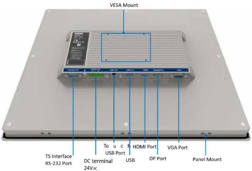
Figure 1.1 FPM-715/717/719 - I/O Port Arrangement .... 4
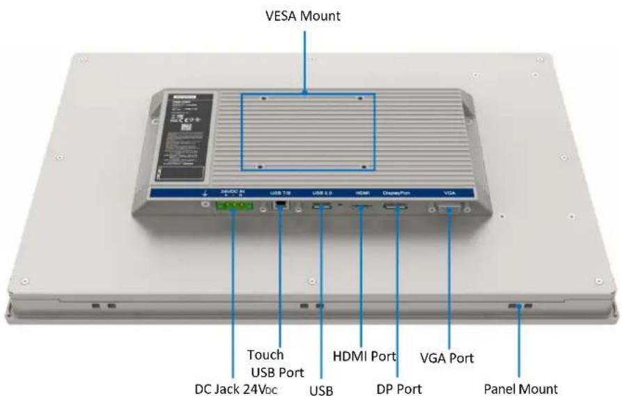
Figure 1.2 FPM-715W/721W/724W - I/O Port Arrangement ..... 4
1.6 Dimensions 5
Figure 1.3 FPM-715/717/719 Dimensions.... 5
Figure 1.4 FPM-715W/721W/724W Dimensions.... 5
Chapter 2 Mounting Methods......7
2.1 Mounting the Monitor/Monter le Moniteur 8
2.1.1 Panel Mounting/Montage Sur Panneau....8
Figure 2.1 Panel Mounting....8
2.1.2 Wall Mounting/Montage Mural 10
Figure 2.2 Wall Mounting.... 10
2.1.3 Desktop Stand Mounting/Montage du support de bureau ..... 11
Figure 2.3 Desktop Stand Mounting 11
Figure 2.4 11
2.1.4 Rack Mounting/Montage en rack 12
Figure 2.5 FPM-715 and FPM-717 Rack Mounting.... 12
Figure 2.6 FPM-719 Rack Mounting.... 13
Figure 2.7 Rack Mounting.... 13
2.1.5 VESA Mounting/Montage VESA.... 14
Figure 2.8 VESA Mounting 14
2.1.6 Power Adapter Bracket Mounting (Optional) 15
Figure 2.9 Power Adapter Bracket Mounting.... 15
Appendix A Touchscreen ....17
A.1 Introduction ...... 18
A.2 Touchscreen Specifications (15"/17"/19"/15.6"/21.5"23.8") 18
A.2.1 Optical Features.... 18
Table A.1: Optical Features 18
A.2.2 Electrical Specifications 18
Table A.2: Electrical Specifications.... 18
A.2.3 Environmental Specifications.... 18
Table A.3: Environmental Specifications 18
A.3 Installing Drivers for Windows OS.... 18
A.4 LED Functions.... 18
Table A.4: LED Functions.... 18
Appendix B OSD Operation Keypad 19
B.1 OSD Board Overview.... 20
B.1.1 OSD Button Descriptions.... 20
Table B.1: OSD Button Descriptions 20
B.2 OSD Key Functions 21
B.2.1 Menu Start 21
B.2.2 Picture.... 22
B.2.3 Geometry.... 23
B.2.4 Color Temperature Menu.... 24
B.2.5 OSD Manager.... 25
B.2.6 Touch Control 26
Table B.2: Touch Control.... 26
B.2.7 ERP Control.... 27
B.2.8 All Reset 28
B.2.9 Exit.... 28
Chapter 1
General Information
Sections include:
Introduction
Specifications
LCD Specifications
Connectors
Dimensions
1.1 Introduction
The Advantech FPM-700 series comprises 15", 17", 19", 15.6", 21.5" and 23.8" industrial-grade monitors with sleek, simple lines and a durable true-flat touchscreen. The FPM-700 series features an IP66-rated front bezel. It supports wide operating temperatures (-20 \~ 60°C) and diverse mounting options.
1.2 Specifications
1.2.1 General
Table 1.1: General
| Specifications FPM-700 series |
| Construction Die-cast aluminum |
| Front Panel Die-cast aluminum - IP66 |
| Video Port HDMI/VGA/DP |
| Mounting Panel Stand, Wall, Panel, and VESA arm (75 x 75mm) |
| FPM-715 Dimensions (W x H x D) 383.2 x 307.3 x 50 mm |
| FPM-717 Dimensions (W x H x D) 410.4 x 343.4 x 51 mm |
| FPM-719 Dimensions (W x H x D) 454 x 379.8 x 48.5 mm |
| FPM-715W Dimensions (W x H x D) 419.7 x 269 x 52 mm |
| FPM-721W Dimensions (W x H x D) 558.4 x 349.8 x 53.2 mm |
| FPM-724W Dimensions (W x H x D) 595.9 x 374.1 x 53 mm |
1.2.2 Touchscreens (Optional)
Table 1.2:
| Specifications FPM-715/717/719 | |
| Type | 5-wire analog resistive |
| Interface | USB/RS-232 |
| Light Transmission | Above 75% |
| OS Support | Windows XP, Vista,7, 8,10,XPe and Linux |
Table 1.3:
| Specifications FPM-715W/721W/724W | |
| Type | Projected capacitive touch |
| Interface | USB |
| Light Transmission | Above 75% |
| OS Support | Windows XP, Vista,7, 8,10,XPe and Linux |
1.3 LCD Specifications
Table 1.4: LCD Specifications
| Specifications | 15" LCD(LEDBacklight) | 17" LCD(LEDBacklight) | 19" LCD(LEDBacklight) | 15.6" LCD(LEDBacklight) | 21.5" LCD(LEDBacklight) | 23.8" LCD(LEDBacklight) |
| Display Type | XGA TFTLCD | SXGA TFTLCD | SXGA TFTLCD | Full HD TFTLED LCD | FULL HDTFT LEDLCD | FULL HDTFT LEDLCD |
| Display Size 15" 17" 19" 15.6" 21.5" 23.8" | ||||||
| Max. Colors 16.2M Max 16.7M Max 16.7M Max 16.7M Max 16.7M Max | ||||||
| Resolution | 1024 x 768 | 1280 x 1024 | 1280 x 1024 | 1920x1080 | 1920x1080 | 1920x1080 |
| View Angle(H/V°) | 176°(V),176°(H) | 170°(V),170°(H) | 170°(V),160°(H) | 160°(V),160°(H) | 178°(V),178°(H) | 178°(V),178°(H) |
| Luminance | 300 cd/m2 | 350 cd/m2 | 350 cd/m2 | 450 cd/m2 | 350 cd/m2 | 350 cd/m2 |
| StorageTemperature | -30 - 70 °C | |||||
| OperatingTemperature | -20 - 60 °C | 0 - 50 °C | ||||
| Contrast Ratio | 2000:1 | 1000:1 | 1000:1 | 500:1 | 1000:1 | 1000:1 |
| Backlight Life | 70,000 hr | 50,000 hr | 70,000 hr | 50,000 hr | 30,000hr | 30,000hr |
1.4 Connectors
The following connectors are situated on the bottom side of the FPM-715/717/719/715W/721W/724W:
DP or HDMI port
DP or HDMI port is connected with a standard DP or HDMI connector through the I/O port of this unit, located on the bottom side of the system unit.
VGA Port (DB-15)
DB-15 connector can be connected to the system via the external 15-pin DB-15 connector located on the bottom side of the system unit.
■ Touchscreen Connector (USB)
This connector will be present only if a touchscreen is installed and it must be connected to the USB port of the PC. The touchscreen cable is included with all orders.
■ DC 24 V Power Input Connector
This connector must be connected to a DC 24 V power supply.
Warning! Please note before connecting the monitor and PC with HDMI / DP or VGA cable:
- If the PC has an OS installed, please confirm its portrait frequency is within an acceptable range.

1.5 Interfaces
Figure 1.1 shows the I/O arrangement
text_image
VESA Mount RS-232 Port TS Interface RS-232 Port DC terminal 24Vdc To u c h USB Port HDMI Port USB DP Port VGA Port Panel MountFigure 1.1 FPM-715/717/719 - I/O Port Arrangement
text_image
VESA Mount 320/DC 84 USB T12 USB 8.0 HDMI Display Port VGA Touch USB Port HDMI Port VGA Port DC Jack 24Vdc USB DP Port Panel MountFigure 1.2 FPM-715W/721W/724W - I/O Port Arrangement
1.6 Dimensions
text_image
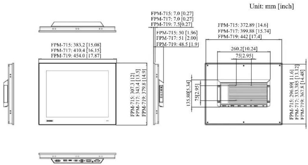
Unit: mm [inch] FPM-715: 383.2 [15.08] FPM-717: 410.4 [16.15] FPM-719: 454.0 [17.87] FPM-715: 307.3 [12] FPM-717: 343.4 [13.5] FPM-719: 379.8 [14.9] FPM-715: 7.0 [0.27] FPM-717: 7.0 [0.27] FPM-719: 7.5 [0.27] FPM-715: 50 [1.96] FPM-717: 51 [2.00] FPM-719: 48.5 [1.9] FPM-715: 372.89 [14.6] FPM-717: 399.88 [15.74] FPM-719: 442 [17.4] 260.2 [10.24] 75 [2.95] 135.80 [5.34] 75 [2.95] FPM-715: 296.89 [11.6] FPM-717: 333.385 [13.12] FPM-719: 367.8 [14.48]Panel Cutout Dimensions: FPM-715: 374.5 x 298.5 mm (14.74 x 11.75 in)
FPM-717: 401.3 x 334.8 mm (15.8 x 13.18 in)
FPM-719: 443.5 x 369.3 mm (17.46 x 14.53 in)
Figure 1.3 FPM-715/717/719 Dimensions
text_image
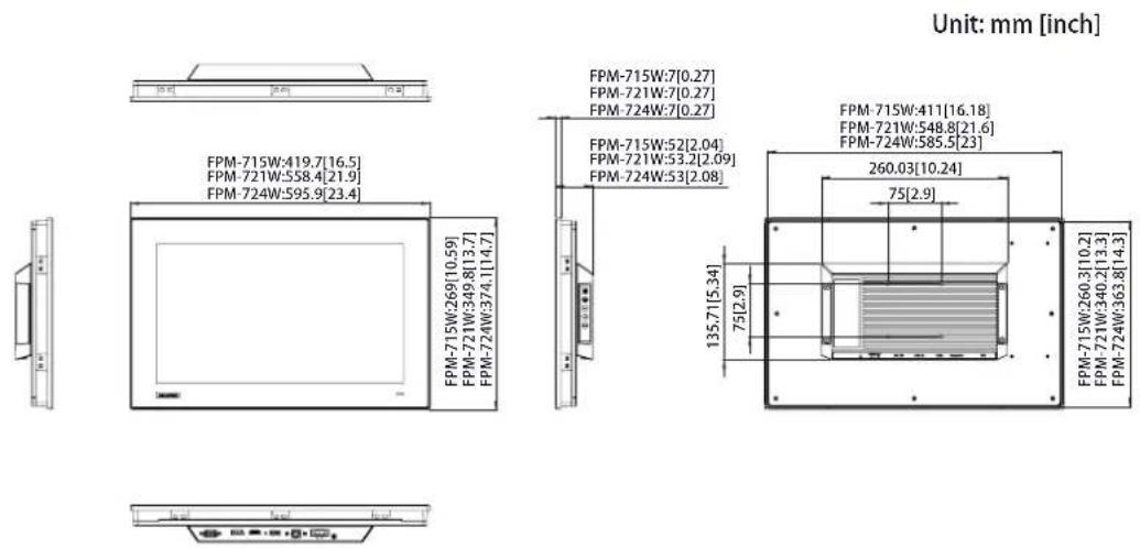
Unit: mm [inch] FPM-715W:419.7[16.5] FPM-721W:558.4[21.9] FPM-724W:595.9[23.4] FPM-715W:269[10.59] FPM-721W:349.8[13.7] FPM-724W:374.1[14.7] FPM-715W:7[0.27] FPM-721W:7[0.27] FPM-724W:7[0.27] FPM-715W:52[2.04] FPM-721W:53.2[2.09] FPM-724W:53[2.08] FPM-715W:411[16.18] FPM-721W:548.8[21.6] FPM-724W:585.5[23] 260.03[10.24] 75[2.9] 135.7[5.34] 75[2.9] FPM-715W:260.3[10.2] FPM-721W:340.2[13.3] FPM-724W:363.8[14.3]Panel Cutout Dimensions: FPM-715W: 412.4-0.4 x 261.7-0.4 mm (16.24 x 10.30 in)
FPM-721W: 549.8-0.4 x 341.3-0.4 mm (21.6 x 13.43 in)
FPM-724W: 587-0.4 x 365.3-0.4 mm (23.11 x 14.38 in)
Figure 1.4 FPM-715W/721W/724W Dimensions
Chapter 2
Mounting Methods
Sections include:
Panel Mounting
Wall Mounting
■ Desktop Stand Mounting
■ VESA Mounting
■ Power Adapter Bracket Mounting (Optional)
2.1 Mounting the Monitor/Monter le Moniteur
The FPM-700 series can be mounted in many different ways.
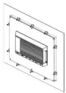
FPM-700 series can be mounted directly on a panel with additional mounting brackets (provided in the accessory box).
Please refer to Figure 2.1 and follow the following steps:
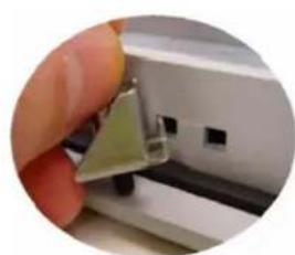
- Secure the 10 x panel brackets around the industrial monitor. See the figure below.
- Secure the panel using the bracket.
natural_image
Technical line drawing of a 3D rectangular enclosure with internal components and dimension lines (no text or symbols)1
natural_image
Technical line drawing of a heat exchanger or cooling unit with mounting brackets and control elements (no text or symbols)2
natural_image
Close-up of a hand holding a small green electronic component, with no visible text or symbols.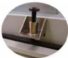
natural_image
Close-up of a mechanical component with a cylindrical pin inserted into a rectangular housing (no visible text or symbols)Figure 2.1 Panel Mounting
Panel Mounting
FPM-715/717/715W
10 clampers with M4 * 25mm screws.
FPM-719 12PCS
12 clampers with M4 * 25mm screws.
Diameter of screw = M4 min.
Length of screw = 25.0 min.
FPM-721W 12PCS
12 clampers with M4 * 25mm screws.
Diameter of screw = M4 min.
Length of screw = 25.0 min.
FPM-724W 14PCS
14 clampers with M4 * 25mm screws.
Diameter of screw = M4 min.
Length of screw = 25.0 min.
Montage sur panneau
2.1.2 Wall Mounting/Montage Mural
If you need to install the FPM-700 Series on a wall, you can use FPM-1000T Series mounting kit. This is offered as an optional accessory for FPM-700 Series. You need to secure this metal bracket to the wall first then, then fasten the FPM-700 Series with the included screws. The metal bracket holds the FPM-700 Series to the wall and completes the wall mounting process.
Please refer to Figure 2.2 and follow the steps shown to mount FPM-700 Series on a wall:
text_image
Wall Mounting 1 2 4 3Figure 2.2 Wall Mounting
Wall Mounting
Screw to fix mounting kit
Diameter of screw = M4.
Length of screw = 6-10 mm
Montage mural
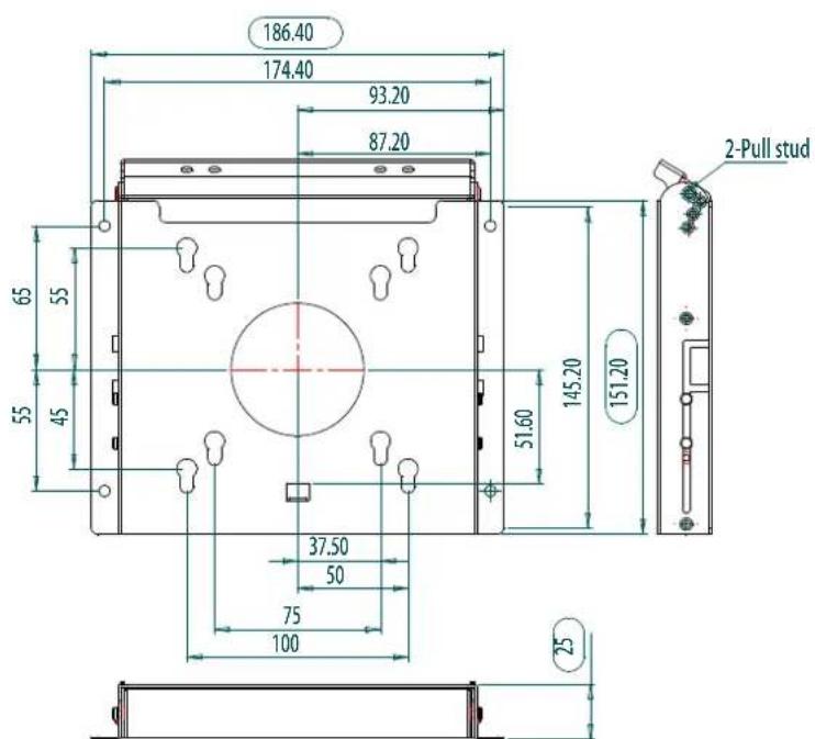
If you have to opted for the desk mount stand, you can use the FPM-1000T mounting kit and secure the stand with 2 x M4 screws to the desk for attachment of the FPM-700 Series mount.
(Note: FPM-1000T Mounting kit are offered as an optional accessory for FPM-700 Series.)
Figure 2.3 Desktop Stand Mounting
text_image
186.40 174.40 93.20 87.20 65 55 55 45 51.60 145.20 151.20 37.50 50 75 100 25 2-Pull studFigure 2.4
Desktop Stand Mounting
Use screws to secure the mounting kit (2 x pcs)
Diameter of screw = M4.
Length of screw = 6-10 mm
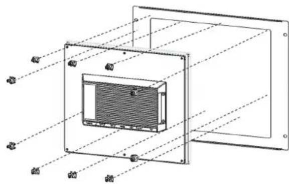
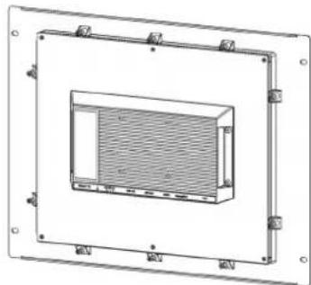
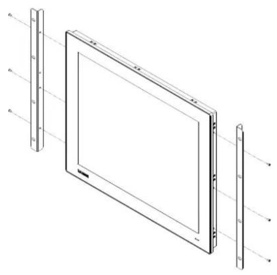
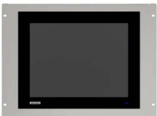
There are optional rack mount kits for mounting the FPM-715/717/719 Series chassis into a rack. (Rack mount kit: FPM-715-RMKE/FPM-717-RMKE/FPM-719-RMKE)
Please refer to Figure 2.4 and follow the following steps:
- Use the provided clampers from the accessory box to fix the FPM to the rack mount brackets. Consult the figure below for guidance.
- Position the FPM monitors onto the rails of the rack mount bracket. Push them inward and fix in place by fastening the clampers, also included in the accessory box.
- Ensure a secure attachment to the rack by using the provided rack screws to fasten the monitors in place.
1
text_image
Technical diagram of a device with labeled components in Chinese, showing internal structure and alignment lines.2
natural_image
Technical line drawing of a rectangular enclosure with internal grating and mounting brackets (no text or symbols)Figure 2.5 FPM-715 and FPM-717 Rack Mounting
1
natural_image
Technical line drawing of a rectangular electronic device with multiple vertical supports and a flat screen, showing internal components (no text or symbols)2
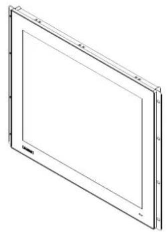
natural_image
Isometric line drawing of a rectangular frame with a central recess and side markers (no text or symbols)Figure 2.6 FPM-719 Rack Mounting
natural_image
Pure electrical circuit lines without any symbols
natural_image
Blank dark rectangular panel with corner markers and no visible text or symbolsFigure 2.7 Rack Mounting
2.1.5 VESA Mounting/Montage VESA
If you use VESA mounting the FPM-715/717/719/715W/721W/724W is a VESA MIS-D, 75, C compliant display equipped with a 75 x 75 mm square-hole pattern. Use M4 screws to attach the mount to the FPM-715/717/719/715W.
natural_image
Technical line drawing of a rectangular electronic device with a central panel and mounting holes (no text or symbols)Figure 2.8 VESA Mounting
Warning! Use a suitable mounting apparatus to avoid risk of injury.

Warning! VESA screw mounting specifications: M4. Depth of the screw hole: 6 mm(Max.).

2.1.6 Power Adapter Bracket Mounting (Optional)
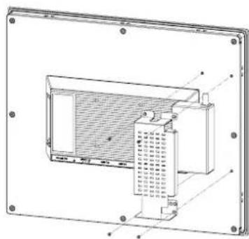
A metal bracket is offered as an optional accessory for FPM-717/719/715W.(P/N: FPM-7000G-ADKE). This helps avoid hanging/loose power adapters.
This metal bracket can be mounted on the back of the monitor in 2 x simple steps:
1
natural_image
Technical line drawing of a device casing with internal components and mounting holes (no text or symbols)2

natural_image
Technical line drawing of a rectangular electronic device with internal components and mounting holes (no text or symbols)Figure 2.9 Power Adapter Bracket Mounting
- Place the metal bracket on top of the power adapter and align it flat against the dedicated holes.
- Secure the metal bracket with the included screws and the metal bracket installation is complete.
This equipment must be installed and removed by a trained skilled person.
Recommendations for maximum cable distance and wires:
Single copper or multi-core copper wire, at 80°C.
Wire range 12-24 AWG.
Wire strip length: 4-5 mm.
Screw torque 7.0 lb-inch.
Appendix
A
Touchscreen
A.1 Introduction
The FPM-715/717/719 touchscreen uses advanced 5-wire resistive technology. The FPM-715W touchscreen uses Projected capacitive (PCAP) touch technology. It provides more accurate sensing capacity than other technologies. The touchscreens are designed for industrial environments and adhere to FCC Class A standards.
A.2 Touchscreen Specifications (15"/17"/19"/15.6"/21.5"23.8")
A.2.1 Optical Features
| Table A.1: Optical Features | ||
| Specification 15" 17" 19" 15.6" | 21.5" | 23.8" |
| Light Transmission | Above 75% | |
| Haze | < 1% | |
A.2.2 Electrical Specifications
| Table A.2: Electrical Specifications | ||||||
| Specification | 15" | 17" | 19" | 15.6" | 21.5" | 23.8" |
| Operation Voltage | 5.5 V or below | |||||
| Contact Current | 70 mA (Maximum) | |||||
A.2.3 Environmental Specifications
| Table A.3: Environmental Specifications | ||||||
| Specification | 15" | 17" | 19" | 15.6" | 21.5" | 23.8" |
| Operating Temperature | -20 -60 °C | 0 ~ 50 °C | ||||
| Storage Temperature | -30 -70 -°C | |||||
| Humidity | 10 - 95%, non-condensing | |||||
A.3 Installing Drivers for Windows OS
The touchscreen has drivers for Windows 7/8/10 and ADV Linux users. The FPM-715/717/719 series need to install Penmount 6000 driver. Please go to below website to download the Penmount 6000 driver then install the driver onto your system.
https://support.advantech.com/support/new_default.aspx
A.4 LED Functions
| Table A.4: LED Functions | |
| ON | Blue |
| StandBy | Orange |
| No Signals | Orange |
Appendix B
OSD Operation Keypad
B.1 OSD Board Overview
The OSD keypad, including 6 x keys and a 2 x color indicators, is designed as the OSD operation interface.
Note! This sheet is only for reference, different models will have different styles, but the functionality is the same.

B.1.1 OSD Button Descriptions
Table B.1: OSD Button Descriptions
| Auto/Exit | Automatically adjust the clock, phase, H-position and V-position.Exit menu. |
| Up/Right/Increase | Increase the brightness.Move the selector to the next option.Increase the gauge value of the selected option. |
| Down/Left/Decrease | Decrease the brightness.Move the selector to the previous option.Decrease the gauge value of the selected option. |
| Menu/Sel | Activate the OSD menu.Enter/confirm the selected option. |
| Source Changes Input video source | |
B.2 OSD Key Functions
Each selected value is stored into LCD memory after SEL signal input or time out. The stored values are not affected if the power is turned off. But the selected value is not available in case a selected mode is changed before time out or power is turned off before time out. TIME OUT -> 5-6 seconds (can be set in OSD Manager) The default definition of input keys is shown below::
B.2.1 Menu Start
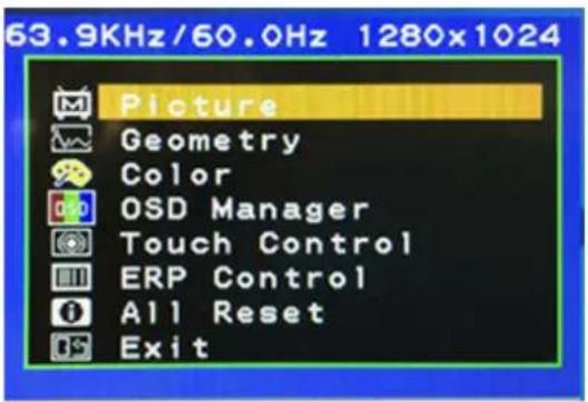
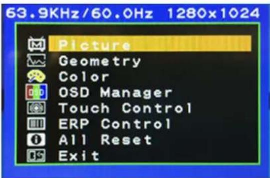
Generate Main Menu
Press MENU Button in OSD function key
■ Main Menu -- Displayed On Screen
text_image
63.9KHz/60.0Hz 1280x1024 Picture Geometry Color OSD Manager Touch Control ERP Control All Reset Exit■ Available Key Functions
Select to exit the menu or wait for time-out
Confirm
Enter the selected option.

Moves the selection up. Select the sub-menu

Detects video source

Moves the selection down. Select the sub-menu
B.2.2 Picture
Generate Main Menu
Select using the up and down button, then press menu button for confirmation.
■ Main Menu -- Displayed On Screen
text_image
63.9KHz/60.0Hz 1280x1024 Picture Geometry Color OSD Manager Touch Control ERP Control All Reset ExitSub-Menu – Displayed On Screen
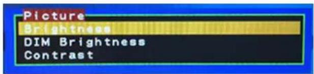
text_image
Picture Brightness DIM Brightness Contrast■ Available Key Functions
Select to exit the menu or wait for time-out

Confirm Enter the selected option.

Moves the selection up. Select the sub-menu

N/A

Moves the selection down. Select the sub-menu
B.2.3 Geometry
■ Generate Main Menu
Select using the up and down button, then press menu button for confirmation.
■ Main Menu -- Displayed On Screen
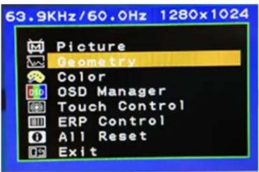
text_image
63.9KHz/60.0Hz 1280x1024 Picture Geometry Color OSD Manager Touch Control ERP Control All Reset ExitSub-Menu – Displayed On Screen
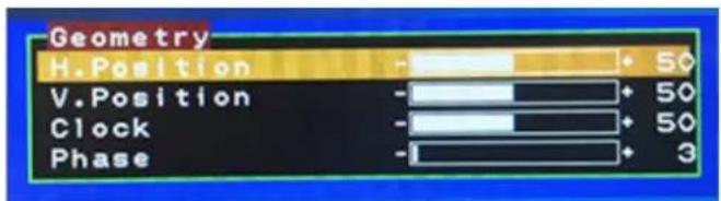
text_image
Geometry H.Position - 50 V.Position - 50 Clock - 50 Phase - 3■ Available Key Functions
Return to the previous menu
Select to confirm

Select to move up N/A


Select to move down
B.2.4 Color Temperature Menu
Generate Main Menu
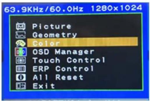
Select using the up and down button, then press menu button for confirmation.
■ Main Menu -- Displayed On Screen
text_image
63.9KHz/60.0Hz 1280x1024 Picture Geometry Color OSD Manager Touch Control ERP Control All Reset ExitSub-Menu – Displayed On Screen
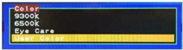
text_image
Color 9300k 6500k Eye Care User Color■ Available Key Functions
Return to the previous menu
Select to confirm

Select to move up N/A


Select to move down
B.2.5 OSD Manager
Generate Main Menu
Select using the up and down button, then press menu button for confirmation.
■ Main Menu -- Displayed On Screen
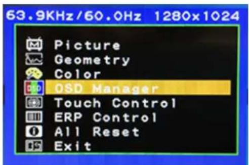
text_image
63.9KHz/60.0Hz 1280x1024 Picture Geometry Color OSD Manager Touch Control ERP Control All Reset ExitSub-Menu – Displayed On Screen
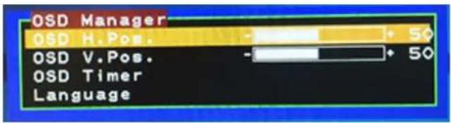
text_image
OSD Manager OSD H. Pos. OSD V. Pos. OSD Timer Language■ Available Key Functions
Return to the previous menu

Select to confirm

Select to move up N/A


Select to move down
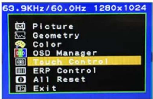
B.2.6 Touch Control
Generate Main Menu
Select using the up and down button, then press menu button for confirmation.
■ Main Menu -- Displayed On Screen
text_image
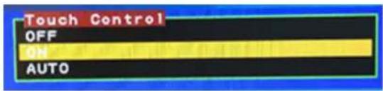
63.9KHz/60.0Hz 1280x1024 Picture Geometry Color OSD Manager Touch Control ERP Control All Reset ExitSub-Menu – Displayed On Screen
text_image
Touch Control OFF ON AUTO■ Available Key Functions
Return to the previous menu

Select to confirm

Select to move up N/A


Select to move down
Table B.2: Touch Control
| Light Signal States |
| Blue/Orange flashing Off/No Signal |
| Orange flashing No Signal |
| Orange stays on On/No Signal |
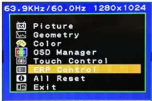
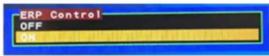
B.2.7 ERP Control
■ Generate Main Menu
Select using the up and down button, then press menu button for confirmation.
■ Main Menu -- Displayed On Screen
text_image
63.9KHz/60.0Hz 1280x1024 Picture Geometry Color OSD Manager Touch Control ERP Control All Reset ExitSub-Menu – Displayed On Screen
text_image
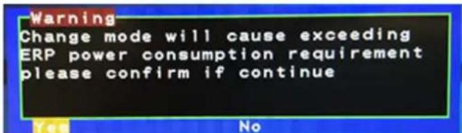
ERP Control OFF ONIf you select ERP mode off, the system will pop up the following warning which means the system will exceeding ERP power consumption requirement but it still workable.
text_image
Warning Change mode will cause exceeding ERP power consumption requirement please confirm if continue■ Available Key Functions
Return to the previous menu

Select to confirm

Select to move up N/A


Select to move down
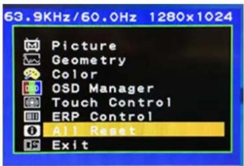
B.2.8 All Reset
Generate Main Menu
Select using the up and down button, then press menu button for confirmation.
■ Main Menu -- Displayed On Screen
text_image
63.9KHz/60.0Hz 1280x1024 Picture Geometry Color OSD Manager Touch Control ERP Control All Reset Exit■ Available Key Functions

Return to the previous menu
Select to confirm

Select to move up Detect


Select to move down
B.2.9 Exit
Generate Main Menu
Select using the up and down button, then press menu button for confirmation.
■ Main Menu -- Displayed On Screen
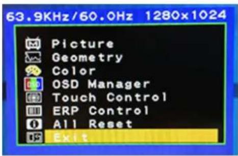
text_image
63.9KHz/60.0Hz 1280x1024 Picture Geometry Color OSD Manager Touch Control ERP Control All Reset Exitwww.advantech.com
Please verify specifications before quoting. This guide is intended for reference purposes only.
All product specifications are subject to change without notice.
No part of this publication may be reproduced in any form or by any means, such as electronically, by photocopying, recording, or otherwise, without prior written permission from the publisher.
All brand and product names are trademarks or registered trademarks of their respective companies.
© Advantech Co., Ltd. 2024