AC1006 - Programmable Logic Controller IFM - Free user manual and instructions
Find the device manual for free AC1006 IFM in PDF.

| Product type | AS-i DP Controller (Programmable Logic Controller) |
| Brand | IFM |
| Model | AC1006 |
| Interfaces | AS-i (1 or 2 masters), Profibus-DP, RS232C |
| Profibus communication speed | 9600 to 12 Mbaud |
| RS232 communication speed | 4800 to 62400 baud |
| Max. RS232 distance | 20 m |
| Mounting | On 35 mm rail |
| Protection rating | IP20 |
| Power supply | 24 V DC (typical) |
| Display | LED and 7-segment numeric display |
| Functions | Standalone controller or gateway, signal preprocessing, data exchange with supervision |
| Local diagnostics | Modes 1 to C: slave display, addressing, speed, etc. |
| Error messages | Display of faulty slaves, network errors, configuration |
| Slave addressing | Manual or automatic, up to 31 slaves per master |
| Configuration | Via PC by serial interface or locally by buttons |
| Operating temperature | 0 °C to 50 °C (estimation) |
| Humidity | Without condensation |
Frequently Asked Questions - AC1006 IFM
User questions about AC1006 IFM
0 question about this device. Answer the ones you know or ask your own.
Ask a new question about this device
Download the instructions for your Programmable Logic Controller in PDF format for free! Find your manual AC1006 - IFM and take your electronic device back in hand. On this page are published all the documents necessary for the use of your device. AC1006 by IFM.
USER MANUAL AC1006 IFM
Function and features 18
Mounting 18
Electrical connection 19
Operating and display elements 20
Diagnosis / adjustment 21
Error messages 28
Functions and features
- The controller integrates 1 or 2 AS-i masters, a mini controller and a Profibus-DP interface.
- it controls the data exchange to the sensor/actuator level
- it processes the peripheral data in the integrated processor (signal preprocessing)
- it works as stand-alone controller with data exchange to the PC (visualisation).
- it communicates with the higher-level control system (in the gateway mode)
Programming interface RS232C
- baud rate 4800 to 62400 baud
- max. distance between controller and host: 20m
- no potential separation from the controller supply
- pin connections: pin2: Rxd; pin 3: Txd; pin 5: Gnd
Programming interface Profibus-DP
- baud rate 9600 to 12Mbaud
- max. distance between controller and host: depending on the baud rate
- potential separation from the controller supply
- up to 31 controllers connected in parallel
- pin connections: pin3: signal B; pin 8: signal A
Mounting
Mount the controller onto a 35mm rail. The unit has protection IP20, therefore it should be mounted in a protected place (e.g. switching cabinet).

Ensure a condensation-free environment. Avoid excessive dust, vibration and shock. The circulation of air through the vents must not be hampered.
Electrical connection

Disconnect power. Connect the unit according to the terminal marking. Never connect the minus potentials to each other or the minus potentials and the PE connection.
Ensure an electrically safe ground connection between the AS-i controller (PE terminal) and the ground connection of the unit.
After application of the supply voltage all the LEDs and the LED display are switched on (LED test); then the version numbers of the hardware and the software are displayed for 1s each (software version controller and software version AS-i master).
Operating and display elements
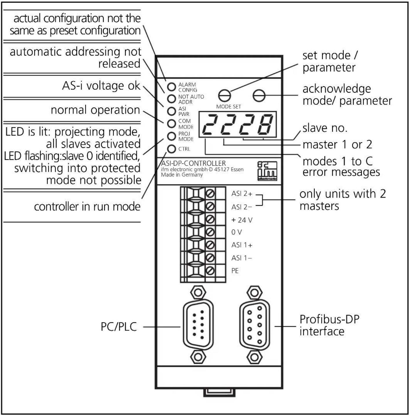
Diagnosis / adjustment
The AS-i controller is served via the higher-level host (PC). Some functions are accessible locally:
| Mode | Action Operating steps | |
| 1 | display list of failed slaves see error messages | |
| 2 | display detected slaves 0/1, 0/2, 2 - 4 | |
| 3 | display projected slaves 0/1, 0/2, 2 - 4 | |
| 4 | display activated slaves 0/1, 0/2, 2 - 4 | |
| 5 | allocate address 0 to a slave 0/1, 0/2, 5 | |
| 6 | allocate an address to slave 0 0/1, 0/2, 6 | |
| 7 | auto addressing on / off | 0/1, 7 |
| 8 | project slaves | 0/1, 0/2, 8 |
| 9 | program processing run/stop | 0/1, 9 |
| A | allocate slave address to Profibus-DP | 0/1, A |
| b | set transfer rate of the serial interface | 0/1, B |
| 8 | locking/unlocking modes > 4 | locking/unlocking |
Assignment of the status nibbles:
| Bit no. | Meaning | = 1 | = 0 |
| 7 | signal preprocessing | running | stopped |
| 6 | AS-i power / configuration | not o.k. | o.k. |
| 5 | running up finished | yes | no |
| 4 | reserved |
0/1 Select mode
| 1 |  Mode SetPress several times until requested mode is displayed Mode SetPress several times until requested mode is displayed | 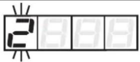 Mode display flashing Mode display flashing | |
| 2 | Mode SetAcknowledgment of the requested mode | Display of the selected mode, display master 1 flashing |
0/2 Select master
| 1 |  Mode SetAcknowledgment of master 1 Mode SetAcknowledgment of master 1 | 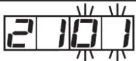 Display master 1,display of 1st slave flashing Display master 1,display of 1st slave flashing |
or
| 1 |  Mode SetPress once Mode SetPress once | → |  Display of master 2 flashing Display of master 2 flashing |
| 2 |  Je SetAcknowledgment of master 2 Je SetAcknowledgment of master 2 | 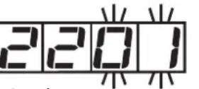 Display master 2,display of 1st slave flashing Display master 2,display of 1st slave flashing |
2/4 Display of identified, projected and activated slaves
| 1 | Select mode and master (operating steps 0/1 and 0/2) |  Display master 1, display of 1st slave Display master 1, display of 1st slave | |
| 2 | Mode SetPress several times | 2102Display of other slaves |
Locking/unlocking modes > 4
| 1 | Select mode (operating step 0/1) | 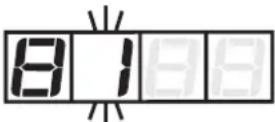 Display of the selected mode Display of the selected mode | |
| 2 |  Mode Set Press twice Mode Set Press twice |  Display of locking flashing Display of locking flashing | |
| 3 |  Mõde Set Press once (= acknowledgment) Mõde Set Press once (= acknowledgment) |  Display locking active Display locking active |
Unlocking: Press both buttons for approx. 5s; as acknowledgment digit 1 is flashing in the LED display.
5 Allocate address 0 to a slave
| 1 | Select mode and master (operating steps 0/1 and 0/2) |  Display master, display of 1st slave flashing Display master, display of 1st slave flashing | |
| 2 | Mode SetPress several times until requested slave is displayed | 5 107Display of slave flashing (here slave 7) | |
| 3 | Mode SetPress once (= acknowledgment) | 5 107Address 0 is stored for selected slave |

Automatic addressing must be switched off (mode 7).
6 Allocate an address to slave 0
| 1 | Select mode and master (operating steps 0/1 and 0/2) |  Display master,first free slave address flashing Display master,first free slave address flashing | |
| 2 |  Mode SetPress several times until requested address is displayed Mode SetPress several times until requested address is displayed |  Display of selected address flashing (here address 24) Display of selected address flashing (here address 24) | |
| 3 |  Mode SetPress once (= acknowledgment) Mode SetPress once (= acknowledgment) |  New address for slave 0 is stored New address for slave 0 is stored |
7 Auto addressing on/off

= automatic addressing OFF
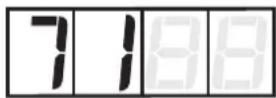
= simple automatic addressing ON (1 slave can be addressed automatically)
= multiple automatic addressing ON (several slaves can be addressed automatically)
| 1 | Select mode (operating step 0/1) |  Display of preset value flashing Display of preset value flashing | |
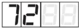
| 2 | Mode SetPress several times until requested setting is displayed | 7 1 8 8Display of newly selected setting flashing (here 1) | |
| 3 | Mode SetPress once (= acknowledgment) | 7 1 8 8New setting is stored |
8 Project slaves
| 1 | Select mode and master (operating steps 0/1 and 0/2) |  Display master, display project mode flashing Display master, display project mode flashing |
| 2 | Mode SetPress once(= acknowledgment) |  New configuration is stored New configuration is stored |
9 Program processing run/stop
$$ \begin{array}{l} = \text { program processing running(RUN mode) } \ \text {(LED"CTRL" = on)} \end{array} $$
$$ \begin{array}{l} = \text { program processing stopped(STOP mode) } \ (\text { LED "CTRL" } = \text { off }) \end{array} $$
1 Select mode (operating step 0/1)
Display of mode and preset value
2 Mode Set Press until requested setting is displayed
Display of newly selected setting (here STOP)
3 Mode Set Press once (= acknowledgment)
New setting is stored
A Allocate slave address to Profibus-DP (default address = 001)
1 Select mode (operating step 0/1)
Display of preset address flashing
2 Mode Set Press several times until requested address is displayed
Display of new address flashing (here 004)
3 Mode Set Press once (= acknowledgment)
New address is stored
The address is only valid for the RS232 interface.
b Set transfer rate of the serial interface
| 1 | Select mode (operating step 0/1) |  Display of preset value flashing Display of preset value flashing | |
| 2 |  Mode SetPress several times until requested setting is displayed Mode SetPress several times until requested setting is displayed |  Display of newly selected setting flashing (here 96) Display of newly selected setting flashing (here 96) | |
| 3 | [5KST ]Mode SetPress once (= acknowledgment) |  New setting is stored New setting is stored |
Possible settings:b_48 (= 4800 baud), b_96 (= 9600 baud), b192 (= 19200 baud = default), b384 (=38400 baud), b576 (= 57600 baud), b624 (= 62400 baud).
Ed Extended diagnosis
| 1 | Select mode (operating step 0/1) |  The default setting flashes The default setting flashes | |
| 2 |  Mode SetPress until the requested setting is indicated Mode SetPress until the requested setting is indicated |  The new selected setting flashes (here Ed-1) The new selected setting flashes (here Ed-1) | |
| 3 |  Mode SetPress once (= acknowledgment) Mode SetPress once (= acknowledgment) | 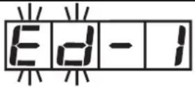 New setting is stored New setting is stored |
Required GSD version: 3.00
Error messages

Display of missing/defective slaves
(digit 2 = master; digits 3 and 4 = slave no.); the slaves are displayed at intervals of seconds.
The list of failed slaves can be stored until the slaves have been replaced.
- Press the SET button twice (for the list of master 1) or SET -MODE - SET (for the list of master 2). The lowest address of the error list is displayed flashing.
- Replace the failed slave by a slave with the same configuration and with the address 0; it will receive the indicated address; (the function “multiple automatic addressing” must be activated). If other addresses are displayed, proceed in the same way until the list has been completed.
- The function will be ended when the slaves have been replaced or the SET button has been pressed.

Bus error or timeout at Profibus-DP interface

Software version AS-i string 1 ≠AS-i string 2

error during initialisation of the Profibus-DP interface module

AS-i master 2: operating mode already active

AS-i master 2: addressing mode already active

AS-i master 2: error during the setting of the new address

AS-i master 2: error during the deletion of the old address

AS-i master 2: slave with old address does not exist

AS-i master 2: slave with new address exists
| E-40 | AS-i master 2 offline/slave 0 exists |
| E-41 | AS-i master 2 not in the projecting mode |
| E-42 | AS-i master 2 not in the projecting mode |
| E-43 | AS-i master 2 not in the projecting mode/ configuration data not valid |
| E-44 | AS-i master 2 not in the projecting mode |
| E-45 | AS-i master 2: offline |
| E-46 | AS-i master 2: parameter value invalid |
| E-47 | AS-i master 1: operating mode already active |
| E-48 | AS-i master 1: addressing mode already active |
| E-49 | AS-i master 1: error during the setting of the new address |
| E-50 | AS-i master 1: error during the deletion of the old address |
| E-51 | AS-i master 1: slave with old address does not exist |
| E-52 | AS-i master 1: slave with new address exists |
| E-53 | AS-i master 1 offline/slave 0 exists |
| E-54 | AS-i master 1 not in the projecting mode |
| E-55 | AS-i master 1 not in the projecting mode |
| E-56 | AS-i master 1 not in the projecting mode/ configuration data not validAS-i master 1 not in the projecting mode |
 | AS-i master 1 offline |
 | AS-i master 1: parameter value invalid |
 | Master 2 does not exist |
 | No plc program loaded |
 | No entry in LDS (list of detected slaves) |
 | No entry in LPS (list of projected slaves) |
 | No entry in LAS (list of activated slaves) |
 | No free slave address available |
| [TAYD] | Key handling disabled |
 | |
 | Function only possible in the projecting mode |
 | Slave 0 does not exist |
 | Target address already allotted |
 | New address could not be allotted |
 | Multiple automatic addressing not active |
 | I/O configuration ≠projected configuration |
 | Incorrect ID code (does not correspond to projected value) |
 | Addressing not possible since "automatic addressing" has not been activated |

Addressing not possible, slaves are missing

Protected operating mode is not active

Slave 0 already exists
Contenu page
natural_image
Pure geometric pattern with repeating diamond shapes on a grid background (no text or symbols)ASI 2+ ASI 2- + 24 V 0 V ASI 1+ ASI 1- PE


Controllers with one master (AC1005)
Input Rating
24V DC 80mA
Output Rating
± 3V DC
Electrical ratings
Controllers with two masters (AC1006)
Input Rating
24V DC 80mA
Output Rating
± 2 × 3V DC