
XL 9ER - Heating Master - Free user manual and instructions
Find the device manual for free XL 9ER Master in PDF.

User questions about XL 9ER Master
0 question about this device. Answer the ones you know or ask your own.
Ask a new question about this device
Download the instructions for your Heating in PDF format for free! Find your manual XL 9ER - Master and take your electronic device back in hand. On this page are published all the documents necessary for the use of your device. XL 9ER by Master.
USER MANUAL XL 9ER Master
natural_image
Icon of an open book with an exclamation mark, enclosed in a diamond shape with a yellow diagonal stripe (no text or symbols)USER AND MAINTENANCE MANUAL
XL 9ER - XL 9SR
| en | it | de | es | fr | nl | da | pl | lv | et | cs | hu | ro | bg | ru | fi | no | kk |
NOTE:
TECHNICAL DATA - DATI TECNICI - TECHNISCHE DATEN - CARACTERÍSTICAS TÉCNICAS - DONNÉES TECHNIQUES - TECHNISCHE GEGEVENS SPECIFIKATIONER - DANE TECHNICZNE - TECHNICKÉ PARAMETRY - ТЕХНИЧЕСКИЕ ХАРАКТЕРИСТИКИ - TEKNISET TIEDOT - TEKNISKE DATA - ТЕХНИКАЛЫК КОРСЕТКІШТЕР КЕСТЕСІ
| MODEL XL 9ER XL 9SR | |||
 | 43 kW-кВт37.000 kcal/h-ккал/ч146.900 Btu/h-БТЕ/ч | 29 kW-кВт25.000 kcal/h-ккал/ч99.300 Btu/h-БТЕ/ч | 43 kW-кВт37.000 kcal/h-ккал/ч146.900 Btu/h-БТЕ/ч |
 | 3,37 kg/h-кг/ч | P1 2,3 kg/h-кг/чP2 3,37 kg/h-кг/ч | |
 | DIESEL-KEROSENEDизель-керосин | DIESEL-KEROSENEDизель-керосин | |
 | 60 l-л 60 l-л | ||
 | ~220-240 V-B (-15%÷10%) 50-60 Hz-Гц0,6 A | ~220-240 V-B (-15%÷10%) 50-60 Hz-Гц0,7 A | |
| ~110-120 V-B (-15%÷10%) 50-60 Hz-Гц1,2 A | ~110-120 V-B (-15%÷10%) 50-60 Hz-Гц1,4 A | ||
 | 69 kg-кг 69 kg-кг | ||
 | 4 - 4,5 4 - 4,5 | ||
 | 4 | 4 | |
 | 0,85 GpH 60°H DANFOSS 0,60 GpH 60°H DANFOSS | ||
 | 10 bar-бар 10 bar-бар / 18 bar-бар | ||

IMPORTANT: In order to have a correct function you must use an electrical generator in class G3 or more (frequency variation ±1%,
tension variation ± 2% . The maximum power of electrical generator must be three time the nominal power of device that you must connect.
NOTE:
▶en - IMPORTANT: Be sure to read and understand this operating manual before assembling, the set up and functioning or the maintenance of this heater. The misuse of this heater can cause serious injuries. Conserve this manual for future reference.
it - IMPORTANTE: Leggere e comprendere questo manuale operativo prima di effettuare l'assemblaggio, la messa in funzione o la manutenzione di questo riscaldatore. L'uso errato del riscaldatore può causare lesioni gravi. Conservare questo manuale a titolo di futuro riferimento.
▶ de - WICHTIG: Lesen und verstehen Sie dieses Handbuch vor der Montage, der Inbetriebnahme oder der Wartung dieses Heizgerätes. Falscher Gebrauch des Heizgerätes kann zu schweren Schäden führen. Bewahren Sie dieses Handbuch für zukünftiges Nachschlagen auf.
es - IMPORTANTE: Leer atentamente este manual de Uso y Mantenimiento, antes de utilizar por primera vez este equipo, prestando mucha atención a todas las recomendaciones indicadas. El uso inadecuado del calentador, puede causar daños graves a personas, animales o cosas. Conservar este manual en lugar seguro y siempre a disposición para futuras consultas.
▶ fr - IMPORTANT: Lire attentivement et comprendre ce manuel avant d'effecteur l'assemblage, la mise en marche ou l'entretien du réchauffeur. Le mauvais usage de celui-ci peut provoquer de graves lésions. Conserver ce manuel comme futur objet de référence.
▶nl - BELANGRIJK: Bestudeer deze handleiding alvorens het apparaat in elkaar te zetten, in gebruik te nemen, of van een onderhoudsbeurt te voorzien. Verkeerd gebruik van de verwarming kan ernstig letsel tot gevolg hebben. Bewaar deze handleiding voor verdere naslag.
▶ da - VIGTIGT: Denne manuale bør læses og forstås før monteringen, ibrugtagningen eller vedligeholdelsen af dette varmeapparat udføres. Et ukorrekt brug af varmeapparatet kan medføre alvorlige personlige skader. Opbevar denne manuale for yderligere henvisninger.
▶ pl - WAŻNE: Przed przystąpieniem do montażu, ustawiania i eksploatacji lub konserwacji promiennikowej nagrzewnicy powietrza należy przeczytać i zrozumieć informacje zamieszczone w niniejszej instrukcji obsługi. Niewłaściwe użytkowanie nagrzewnicy może skutkować poważnymi obrażeniami ciała. Instrukcję należy zachować do wykorzystania w przyszłości.
▶ Iv - SVARİGI: Uzmanîgi izlasiet visas instrukcijas pirms såksiet iekârtas ekspluatâciju vai tehnisko apkopi. ěeneratora nepareiza lietođana var izraisît nopietnus miesas bojâjumus: tâdus kâ apdegumi ugunsgrçka vai sprâdziena gadíjumâ, elektriskais doks, nosmakšana no tvana gâzes.
▶ et - OLULINE TEAVE: Enne soojendi paigaldamist, käivitamist või hooldamist lugege kogu käesolev kasutusjuhend hoolikalt läbi. Soojendi ebaõige kasutamine võib tekitada tõsiseid kehavigastusi. Hoidke kasutusjuhend alles.
▶ cs - DÜLEŽITÉ UPOZORNĚNÍ: Než přistoupíte k montáži, nastavení a používání či údržbě naftového infračerveného topidla, pečlivě si přečtěte informace uvedené v tomto návodu k obsluze. Nesprávné používání topidla může mít za následek vážná zranění. Návod pečlivě uschovejte pro pozdější použití.
▶ hu - FONTOS: A hősugárzó összeszerelése, beállítása, működtetése vagy karbantartása előtt figyelmesen olvassa el és értse meg az alábbi használati utasításban leírt információkat. A hősugárzó helytelen használata komoly testi sérüléseket okozhat. A használati utasítást tartsa meg későbbi használatra is.
▶ ro - IMPORTANT: înainte de a trece la montarea, setarea, punerea în funcțiune sau orice altă operație legată de conservarea încălzitorului, trebuie să citiți cu atenție și să înțelegeți bine prezenta instrucțiune. Utilizarea neadecvată a încălzitorului poate duce la accidente și răniri. Instrucțiunile trebuie păstrate pentru a fi utilizate în viitor.
bg - ВАЖНО: Преди започване на работа на инфрачервения въздушен отоплител или на каквито и да било действия свързани с поддръжката му, внимателно трябва да се прочете тази инструкция за експлоатация. Неправилната експлоатация на инфрачервения отоплител може да доведе до сериозни наранявания, в резултат на изгаряне, пожар, експлозия, токов удар или отравяне с въглероден окис.
▶ ru - ВАЖНО: Перед началом монтажа, установки и эксплуатации или техобслуживания инфракрасного нагревателя воздуха следует ознакомиться и соблюдать указания, содержащиеся в данной инструкции по обслуживанию. Неправильная эксплуатация нагревателя может стать причиной серьезных телесных повреждений. Инструкцию следует сохранить для использования в будущем.
▶ fi - TÄRKEÄÄ: Lue ja ymmärrä tässä käyttöoppaassa annetut ohjeet ennen tämän generaattorin kokoamista, käyttöönottoa tai huoltoa. Generaattorin vääärä käyttö vai aiheuttaa vakavia henkilövahinkoja. Säilytä tätä käyttöohjetta tulevaa tarvetta varten.
▶ no - VIKTIG: Les og forstå denne manualen før du utfører montering, igangsetting eller vedlikehold av dette varmeapparatet. Feil bruk av varmeapparatet kan føre til alvorlige skader. Ta vare på denne manualen for fremtidig bruk.
▶ kk - МАНЫЗДЫ: Инфрақызыл ауа жылытқышты жәндеу, орнату және пайдалану алдында немесе орган қызмет көрсетуалдында қызмет көрсету бойынша осы жетекшілікте келтірілген шарттарды оқып, оларды орындау керек. Жылытқышты дұрыс пайдаланбау ауыр дене жаракаттарының себепшісі болуы мумкін. Жетекшілікті болашақта жүгіну үшін сақтаған жән.
NOTE:
INDEX
- PRODUCT PRESENTATION
- UNPACKING
- SAFETY INFORMATION
- PRODUCT IDENTIFICATION
- COMBUSTIBLE
- THEORY OF OPERATION
- OPERATING INSTRUCTION
- SAFETY DEVICE
- MOVING AND TRANSPORTATION
- PREVENTATIVE MAINTENANCE SCHEDULE
- ACCESSORIES
- FAULTS AND THEIR LIKELY CAUSES
PRODUCT PRESENTATION
XL 9 is a generator of heat by radiation. Radiation technology is based on the same physical principle behind the warmth of sunlight. The sun heats bodies without a flow of warm air but by waves of radiation. The radiation method is becoming highly popular among professional clients because of the countless advantages it offers. XL 9 was designed on the basis of this physical principle and has become irreplaceable in environments which require a constant, even source of heat for warmth, defrosting and drying. In addition, its extremely low noise level makes it suitable for working without having to put up with the noise that other types of heater normally produce. The generator has rubber wheels for ease of movement and it can also be raised and set at different heights by means of eyebolts. Its extended autonomy and automatic thermostat function grant the operator maximum freedom of use. The external fuel-tank indicator provides an easy check on whether fuel needs topping up. The SR model has a dual power device that enables a more efficient use of the machine under different conditions and during the various seasons of the year.
UNPACKING AND PACKAGING UNPACKING
- Remove the supports used to pack the appliance (Fig. 1).
- Open top side of the box.
- Remove the cardboard from the top.
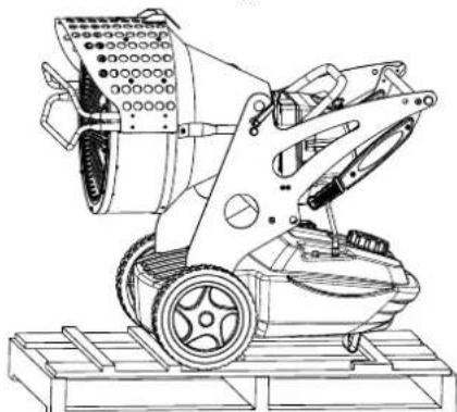
- Remove the supports that hold the generator to the pallet (Fig. 2).
• Delicately lower the heater off the pallet. - Dispose of the material used to pack the generator according to the current government regulations in your area.
- Check the machine for eventual damages incurred during transportation, if the machine appears damaged immediately inform the store where you purchased it.

natural_image
Line drawing of a rectangular box with internal compartments and a wooden base (no text or symbols)Figur 1 - Packaging
ON PACKAGING AND STORING
If the generator needs to be placed in storage, or if it has suffered major damage in transport, or needs to be repaired:
- Check for damage, in particular of a nature which could cause loss of fuel. In this case, empty the tank of the remaining fuel.
- For storage, place the generator on the same pallet from which it was unpacked and, for return, on any suitable EPA-branded euro-pallet.
- Firmly anchor the generator to the pallet (Fig. 2).
- Whenever possible, slide the cardboard packing from the top down over the pallet and anchor it firmly using suitable materials (Fig. 1).
- Store the machine in a suitable, dry place and do not stack more than two. Despatch the generator preferably as shown Fig. 1 or at least as shown in Fig. 2.
natural_image
Technical line drawing of a mechanical device with wheels and mounting base (no text or symbols)Figur 2 - On pallett
SAFETY INFORMATION
WARNING

IMPORTANT: This air heater has been designed for mobile and temporary professional applications. It has not been designed for domestic use nor for thermal comfort of human.
IMPORTANT: Read this entire manual carefully before operating or effectuating any maintenance procedures on this generator. The misuse of the generator can cause serious of fatal injuries due to burns, fires, explosions, electrical shock or asphyxiation from carbon monoxide.
DANGER: Carbon monoxide asphyxiation can be fatal.
Carbon Monoxide Asphyxiation - The first symptoms of carbon monoxide asphyxiation are similar to that of the flu, headaches, dizziness and/or nausea. These symptoms could be caused by the malfunctioning of the generator. In this case go outside immediately. Have the generator repaired. Then you may start it again. Some people are more affected by the effects of carbon monoxide than others, especially pregnant women, those who suffer from heart or lung disease or anaemic people; also those who have consumed alcoholic beverages, and those who are at high altitudes. Be sure to read and understand all of the warnings. Conserve this manual for future reference: it will provide you with instructions to operate your generator safely and correctly.
- Use only kerosene or diesel to diminish the risk of fire or explosion. Never use gasoline, naphtha, paint thinners, alcohol or other highly flammable combustants.
- Filling the tank:
a) The personnel charged with filling the tank should be qualified and completely familiar with the factory instructions and the current governmental regulations regarding the secure provision of generators.
b) Use only the type of fuel expressly specified on the identification plate located on the generator.
c) Before filling the tank, extinguish all of the flames, including the pilot light and wait for the generator to cool down.
d) While filling the tank inspect all of the fuel lines and their junctions to check for fuel losses. Any losses must be repaired before starting the generator again.
e) Under no circumstances should you conserve a quantity of combustible superior to that which is necessary to maintain in function the heater for one day in the same building or nearby the heater. The fuel storage cisterns should be located in a separate building.
f) All of the fuel tanks should be located a minimum safety distance from the heater, (like current government regulation), as well as oxyhydrogen blowpipe/ torches, welding equipment and similar ignition sources (with the exception of the fuel tank incorporated in the generator).
g) The fuel should be stored in areas where the flooring will not soak up any fuel spills or any drips of fuel line, the flame underneath that could cause a fire.
h) All fuel storage must be effectuated in compliance with the current government regulations.
- Never use the generator in rooms where gasoline, paint thinner, or other highly flammable materials are located.
- While the heater is in use follow all of the local ordinances and current government regulations.
- Heaters used close to large pieces of fabric, curtains or other similar materials must be situated at a safe distance from these objects. The minimum safety distance is that which is advised by the current regulations in the your country. It is also advisable to use fireproof materials for coverings. Such materials should be fastened in a safe manner, so as to avoid their catching fire and prevent interference with the generator caused by wind.
- Use only well ventilated areas. Predispose an opening or at least an air exchange system that meets the current governmental regulations in your area so that fresh air will be provided.
- Supply the generator with the proper voltage and frequency as specified on the identification plate.
- Use only extension cords with three wires correctly connected to a grounded plug.
- The minimum safety distance is the distance required by the current governmental regulations in your area.
- Place the generator in a position so that when it is hot or in function it will be on a stable and level surface, so that you avoid starting a fire
- When you move or store the generator, maintain it in a level position in order to avoid fuel loss.
- Keep children and animals away from the generator.
- Disconnect the generator when it is not in use.
- When it is controlled by another device (like a thermostat or a timer), the heater could turn itself on at any time.
- Never place the generator in inhabited rooms.
- Never obstruct the aspiration or dissipation vents.
- When the heater is hot, connected to the power supply or in function it should never be moved, handled, or refilled and no maintenance should be performed on it.
- Smoke that is produced from the first combustion is due to the evaporation of organic materials (ceramic) present in the combustion tank and anticorrosion oil present on the surface of the burner. After a few minutes the smoke will stop.
- The environmental operating temperature is -30^ + 40^ .
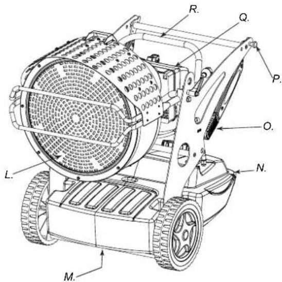
PRODUCT IDENTIFICATION
Figur 3

Figur 4
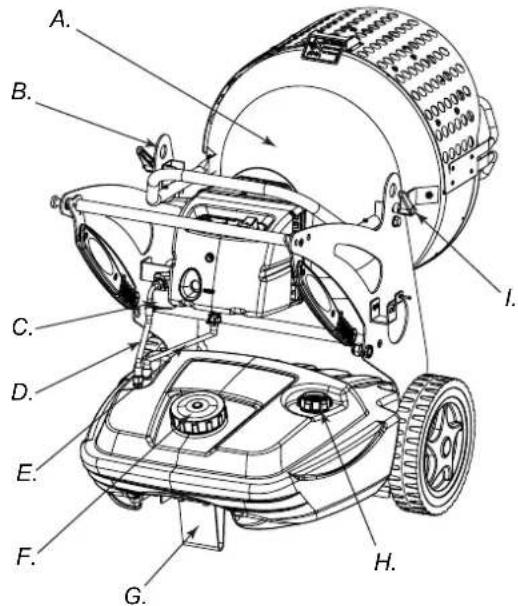
A. Combustion chamber, B. Hole for raising generator, C. Fuel filter or pre-heated filter (optional), D. Fuel supply, E. Fuel Return, F. Fuel tank cap, G. Foot or wheel (optional), H. Fuel level indicator, I. Block of the group combustion, L. Radiant deflector, M. Fuel drain plug, N. Fuel tank, O. Handle to move the generator, P. Hinge block, Q. Burner, R. Inclination regulator
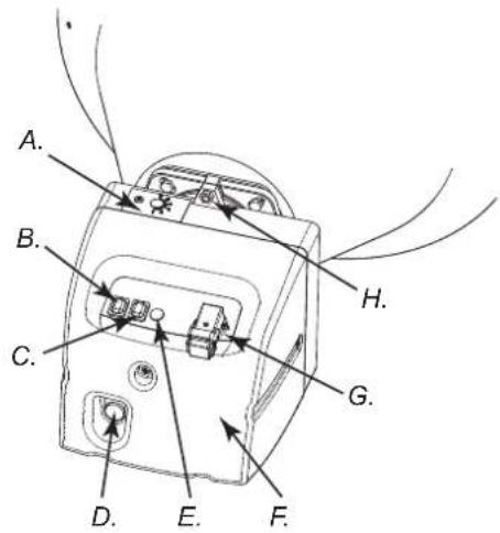
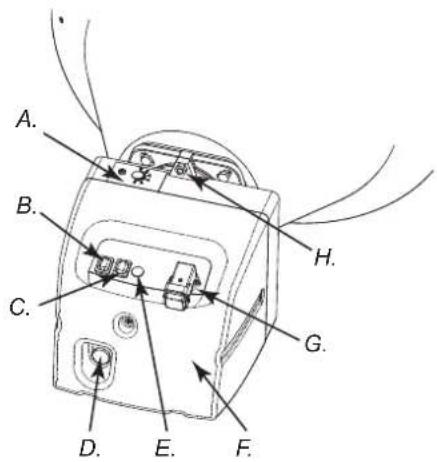
Figur 5 - Function controls

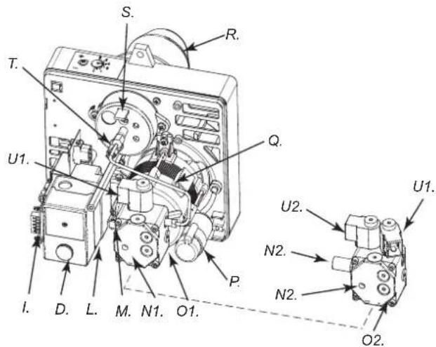
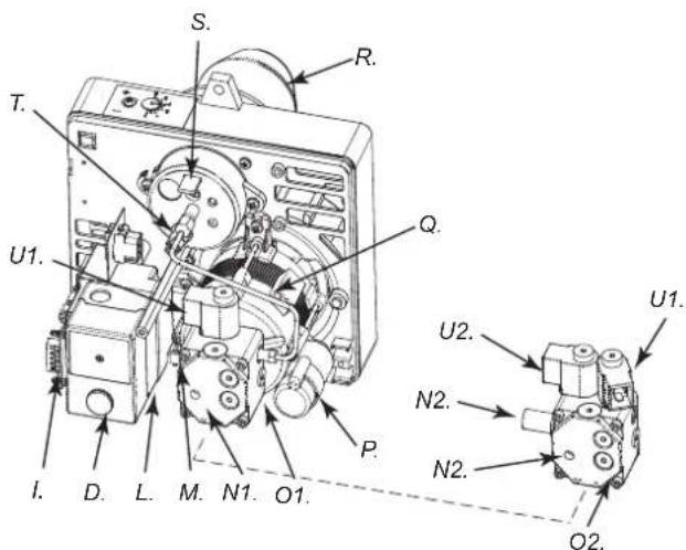
Figur 6 - Components burner
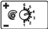
A. Air vent regulator, B. Lighted ON/OFF button, C. ON/OFF switch depending on power option (XL 9SR), D. RESET Button, E. Power indicator, F. Burner coffer, G. Thermostat plug, H. Screw for burner block, I. Post-ventilation device, L. Flame control device, M. Transformer, N1. Pressure regulator (XL 9ER) of the pump, N2. Pressure regulator (XL 9SR) of the pump, O1. (XL 9ER) fuel pump, O2. (XL 9SR) fuel pump, P. Condenser, Q. Motor, R. Burner tube, S. Combustion head regulator, T. Photoresistance, U1. Electrovalve 1° flame step (XL 9ER-SR), U2. Electrovalve 2° flame step (XL 9SR)
COMBUSTIBLE
WARNING: The generator runs ONLY on kerosene or diesel fuel.
The use of impure combustible can cause:
- Blockage of the combustible filter and nozzle.
- Formation of carbonaceous deposits on the electrodes.
At low temperatures use non-toxic antifreeze.
THEORY OF OPERATION
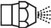
The ventilation needed for proper combustion is produced by a fan inside the burner. The air exits the burner sleeve and mixes with the fuel which is nebulised by a high-pressure nozzle. The fuel is aspirated from the fuel tank by a rotary pump which forces it at high pressure up to the nozzle for nebulisation.
OPERATING INSTRUCTIONS
WARNING: Before putting the generator in function, and therefore before connecting it to the electrical system, you must check to see if the electrical systems technical characteristics correspond to those on the identification plate of the generator.
STARTING THE GENERATOR
- Follow all of the safety information.
- Fill the tank with diesel fuel or kerosene.
- Close the fuel cap.
- Plug the alimentation cord into a grounded wall plug with the same tension as the one written on the generator's identification plate.
STARTING WITHOUT A THERMOSTAT
• XL 9ER
Set the switch (B Fig. 5) to the ON position (I). It begins the period of pre-ventilation and after approximately 10 seconds ones the combustion has beginning.
• XL 9SR
WARNING: Before starting the generator to make sure that the button (C Fig. 5) is in position 🔒
Set the switch (B Fig. 5) to the ON position (I). It begins the period of pre-ventilation and after approximately 10 second ones the combustion has beginning.
For having the maximum potentiality portare set the switch (C Fig. 5) to the vposition.
STARTING WITH A THERMOSTAT
Regulate the thermostat or the control device (for example a timer), if connected, so that it will allow the generator to function.
WARNING: The generator can ONLY function automatically when the control device, for example a Thermostat or a Timer, is connected to the generator. To connect the control device to the machine consult the paragraph entitled "ELECTRIC DIAGRAM".
Before starting the machine or after the fuel line has been completely emptied, the fuel flow to the nozzle should be insufficient to cause the intervention of the security device which controls the flame (see the "SAFETY DEVICE" paragraph) that stops the generator. In this case, after having waited approximately one minute, push the Reset button (D Fig. 5 and 6) and start the machine.
If the machine isn't working you should first control the following:
- Make sure that the fuel tank (N Fig. 4) still contains fuel.
- Press the Restart button (D Fig. 5 and 6).
If the generator still isn't functioning consult the "FAULTS AND THEIR LIKELY CAUSES" paragraph to identify the cause.
WARNING: Before the second ignition (machine extinguished and adequately cold) to assure the blocking of the screws that block the anterior deflector (L Fig. 4).
WARNING: The electric power that feeds the generator must be grounded and have a differential magnetic-thermal switch. The generator's electric cord must be attached to a plug equipped with a section switch.
TURNING THE GENERATOR OFF
Turn the switch (B Fig. 5) to the OFF position (O) or turn the thermostat or control device (Timer) off if there is one connected. The flame will go out and the ventilation will continue until it has finished its post-ventilation cycle (cooling down).
WARNING: Before unplugging the alimentation cord from the wall, wait until the post-ventilation cycle is completely finished (it will take approximately 3 minutes to cool down).
SAFETY DEVICE
The generator is equipped with a safety device (L Fig. 6), which controls the flame. If one or more anomalies occur when the generator is functioning, the device will block the burner and the RESET button (D Fig. 5 or 6) will light up.
The generator also has a post-ventilation device which enables optimal, automatic cooling of the combustion chamber for some 3 minutes.
Before turning the generator on again you must identify and eliminate the cause that blocked the machine.
MOVING AND TRANSPORTATION
NOTICE: Before raising or moving the machine ensure that the fuel tank caps (F and H Fig. 3) are firmly closed.
TRANSPORT
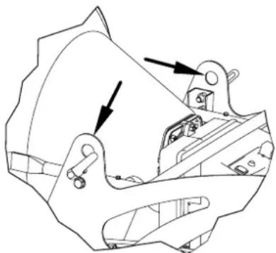
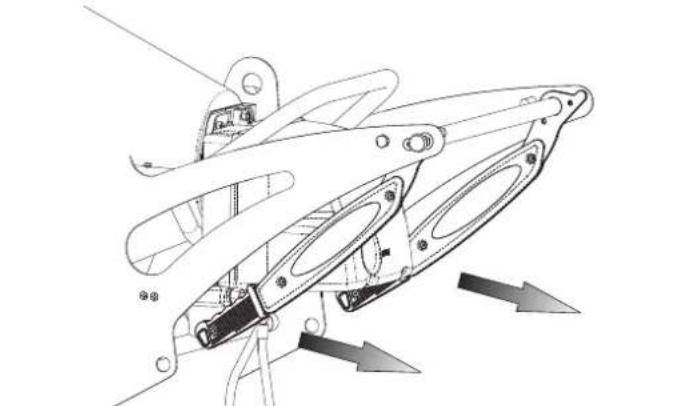
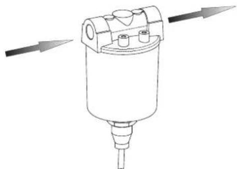
The generator is easy to move and it may be fixed in a raised position thanks to its special eye-bolt mechanism (B Fig. 3 or Fig. 7). This enables it to be set in the most suitable position for heating, defrosting and drying.
natural_image
Technical line drawing of a mechanical component with arrows indicating motion or assembly (no text or symbols)Figur 7 - Hooks in order to raise
MOVEMENT
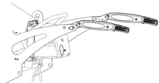
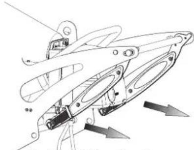
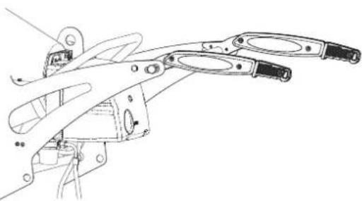
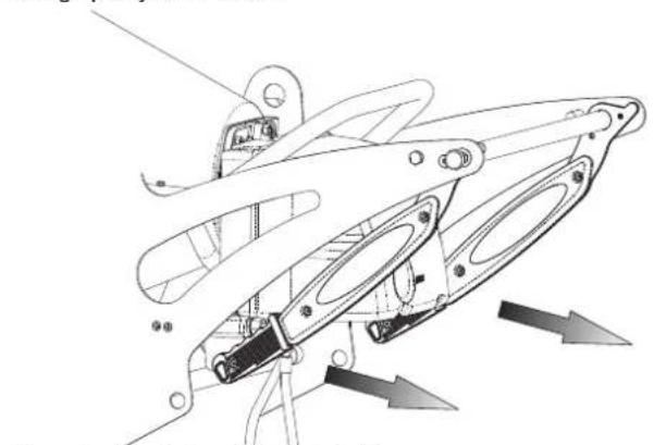
Before picking up or moving the machine you must check to insure that the tank caps (G Fig. 3) are tightly shut. The generator may be supplied with a rotating wheel. In this case, if the flooring allows it you may push the generator like a cart. In the case the machine does not have rotating wheels it is necessary to unblock the hinge (P Fig. 4) located on one of the lateral struts of the generator. Lower the handle from its "resting position" (Fig. 8) Turn the handle to the "Transportation Position" (Fig. 9). Lift the generator and position it so that it is resting on the two anterior wheels.
natural_image
Technical line drawing of a mechanical assembly with directional arrows indicating motion (no text or symbols)Figur 8 - Position close handles
natural_image
Technical line drawing of a mechanical clamp or tool assembly (no text or symbols)Figur 9 - Position open handles
WARNING: Before moving the machine you must: turn the machine off by following the indications provided in paragraph "TURNING OFF THE GENERATOR"; unplug the electrical source by pulling the plug out of the wall and waiting for the generator to cool down.
PREVENTATIVE MAINTENANCE SCHEDULE
WARNING: Before beginning any maintenance operation you must: turn off the machine following the instructions in the "TURNING OFF THE GENERATOR" paragraph; unplug the electrical alimentation by unplugging the cord from the wall plug and waiting for the generator to cool down.
The instructions in this paragraph regarding the time between service checks depend a lot on the cleanliness of the fuel and the type of environment the generator is used in - the times given are for well-ventilated environments with little dust and considering the use of clean fuel.
Every 50 hours of operation you must:
- Dismantle the on-line cartridge (see "CLEANING THE FUEL FILTER") extract and clean the cartridge.
Every 200 hours of operation you must:
- Dismantle the pump filter (see "CLEANING THE PUMP FILTER) extract and clean it.
Every 300 hours of operation you must:
- Dismantle the burner and clean inside the burner's tube, the flame disk and the electrodes regulating, if necessary the distance (see "CLEANING OF THE BURNER").
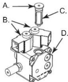
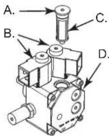
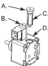
CLEANING THE FUEL FILTER
- Unscrew the plastic cup and extract the filtering element (cartridge).
- Clean it well with kerosene.
- Insert the filter element back into its place and screw the cup back into the main body of the combustion filter.
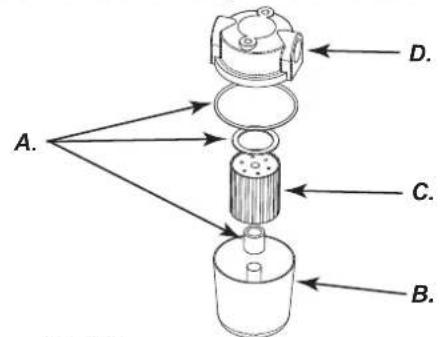
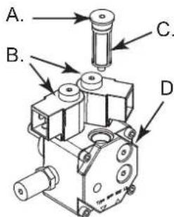
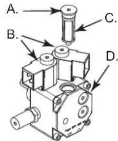
A. O-rings, B. Plastic cup, C. Filtering element, D. Body of IN/ OUT of the fuel
Figur 10 - Filter
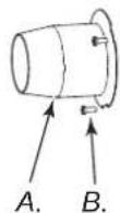
CLEANING THE PUMP FILTER
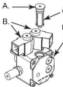
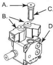
- Dismantle the burner coffer (F Fig. 5), to identify the pump of the burner (O Fig. 6).
- Unscrew the nut (A Fig. 11) that blocking the filtering element to the pump.
- Extract the filtering element (C Fig. 11) outside its place.
- Clean it well with kerosene.
- Insert the filtering element back into its place and screw the nut to the pump.
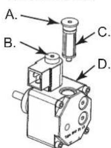
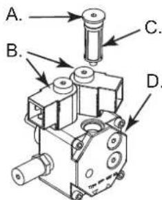
A. Nut for blocking the pump filter, B. Single electrovalve for XL 9ER doble electrovalve for XL 9SR, C. Filter, D. Pump
Figur 11 - Pomp of burner
CLEANING THE BURNER
- Remove the screw (H Fig. 5) that blocks the burner (A Fig. 3) in the combustion chamber.
- Extract the burner from the combustion chamber (Fig. 3).
- Remove the three screws (B Fig. 12) that hold the burner tube (A Fig. 12).
- Dismantle the tube.
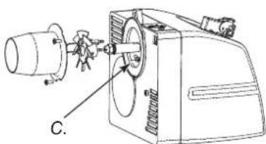
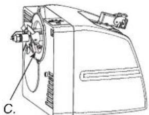
- Remove the screw (C Fig. 13) that holds the group diskflame-electrodes and pull out the nozzle holder (F Fig. 14).
- Clean the flame disk (D Fig. 14) and the electrodes (E Fig. 14).
- Unscrew the nozzle (G Fig. 14) from the nozzle holder (F Fig. 14) clean it and if necessary replace it.
- Mount the nozzle (G Fig. 14) in its holder.
- Remount the group diskflame-electrodes placing it at a correct distance as the illustration (Fig. 14) shows.
Figur 12 - Disassembly shell-burner

natural_image
Technical line drawing of a mechanical device with labeled component C (no text or symbols beyond label)Figur 13 - Disassembly group diskflame-electrodes
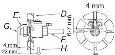
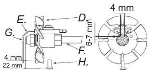
Figur 14 - Distances electrodes nozzle
A. Burner tube, B. Screw of the burner tube, C. Screw of the group disk flame-electrodes, D. Flame disk, E. Electrodes, F. Tube, G. Nozzle, H. Screw
ACCESSORIES
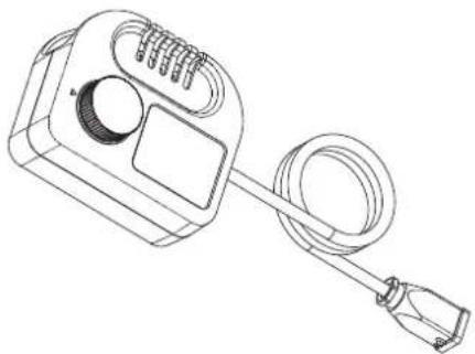
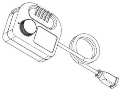
THERMOSTAT

natural_image
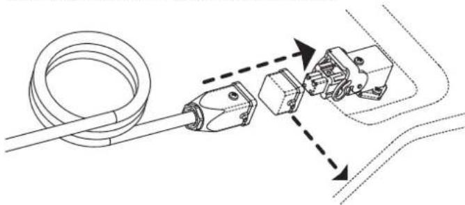
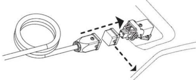
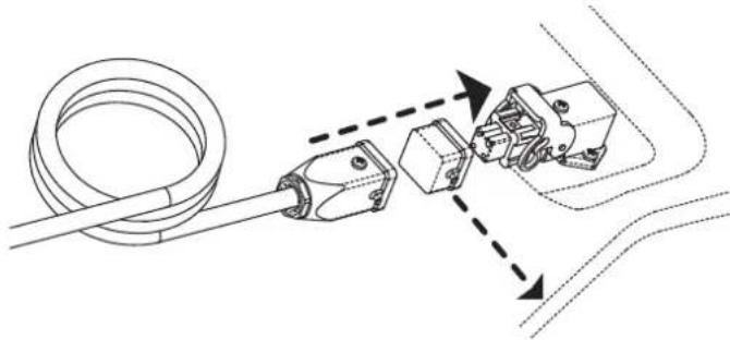
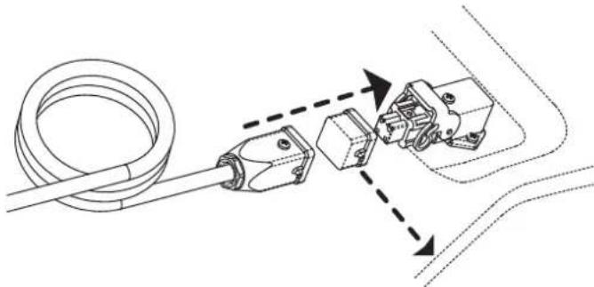
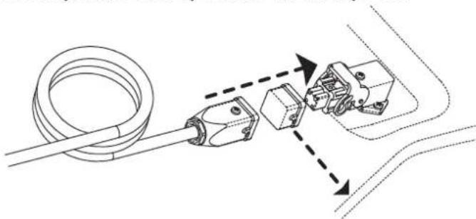
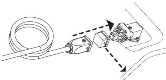
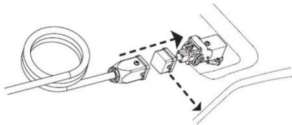
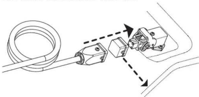
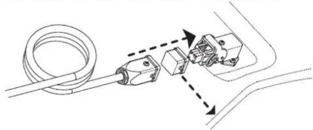
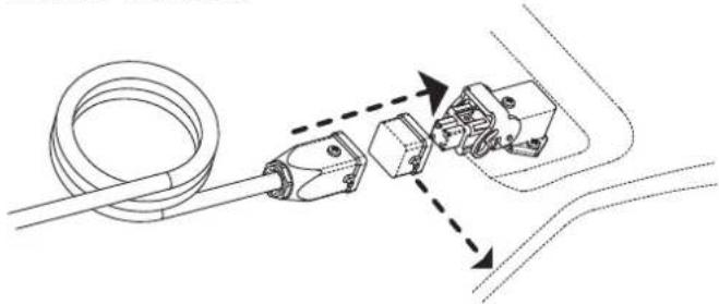
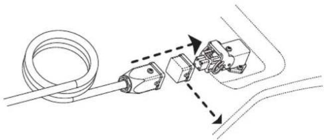
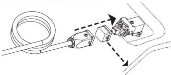
Line drawing of a handheld electrical device with coiled cable and control panel (no text or symbols)CONNECTING THE CONTROL DEVICE
natural_image
Technical diagram showing a cable being inserted into a connector with two internal components, connected by dashed arrows indicating assembly or connection (no text or symbols present)WARNING: Before beginning any maintenance operation you must: stop the machine according to the instructions provided in the paragraph "TURNING OFF THE GENERATOR"; disinsert the electrical supply by unplugging it and waiting for the generator to cool down.
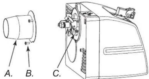
PRE-HEATING FILTER
natural_image
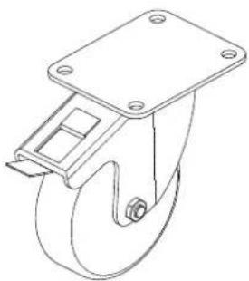
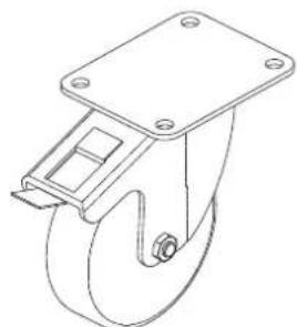
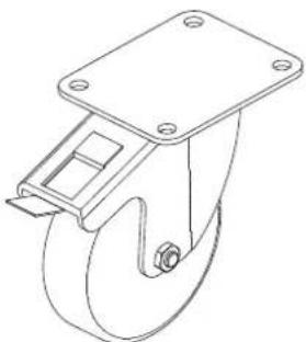
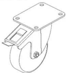
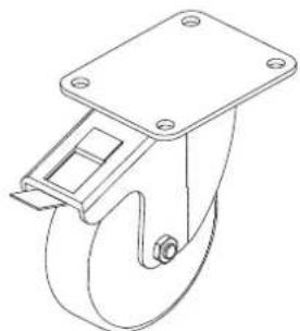
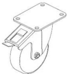
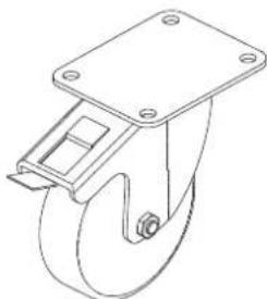
Technical line drawing of a mechanical component with directional arrows indicating flow or movement (no text or symbols)ROTATING WHEEL WITH BRAKES

natural_image
Line drawing of a mechanical lifting device with a curved wheel and mounting bracket (no text or symbols)FAULTS AND THEIR LIKELY CAUSES
WARNING: Before beginning any maintenance operation you must: stop the machine according to the instructions provided in the paragraph “TURNING OFF THE GENERATOR”; disinsert the electrical supply by unplugging it and waiting for the generator to cool down.
| SYMPTOMS POSSIBLE CAUSE SOLUTION | ||
| The machine stops with ☐ame.RESET button (D Fig. 5 o 6) on | 1. Photo-resistance circuit is broken or the Photo-resistance is dirty with smoke residue2. Dirty fuel ☐ter3. Flame Control device Circuit is broken4. Flame disk or tube (Fig. 12, 13, 14) dirty | 1. Clean or replace the Photo-resistance2. Remove ☐ter and clean it3. Replace the ☐ame control the circuit4. Dismantle and clean it |
| The machine stops, spraying fuel without verifying the ☐ame. RESET button (D Fig. 5 o 6) on | 1. The electrical system is not compatible2. Ignition Transformer (M Fig. 6) disconnected or broken3. Ignition Transformer wires short circuit to ground4. The electrodes are not at the proper distance5. The electrodes short circuit to ground because they are dirty or the insulation is damaged | 1. Verify the entire circuit2. Replace it3. Replace it4. Reposition them at the correct distance (see Fig. 14)5. Clean them or, if necessary replace them |
| The machine doesn't spray fuel and stops.RESET button (D Fig. 5 o 6) on | 1. Photo-electric cell sees a strong source of light2. The power supply is missing a phase to the motor3. Fuel is not arriving to the pump4. No fuel in the tank5. Nozzle clogged | 1. Place the machine so that the light source does not directly face the front deflector2. Control the electric system3. Control the fuel supply lines (D Fig. 3)4. Resupply the fuel tank5. Dismantle and clean or replace it |
| The burner doesn't start 1. The | control device (Thermostat or Timer) is on2. Short circuit in Photo-resistance (T Fig. 6)3. Power loss due to: disconnected switch (4) or disconnected main switch due to power loss in the line4. The installation of the control device (Thermostat or Timer) is not correct5. Break inside the ☐ame control device6. Fuse inside the burner bonnet | 1. Raise the value or control the Timer settings2. Replace it3. Turn oil the electric system and then turn oil the switches or wait for the power supply to return4. Control the installation following the description in the “CONNECTING THE CONTROL DEVICE” paragraph5. Replace it6. Open the burner coller (F Fig. 5) and replace it |
| Flame is not well confirmed with an unpleasant odour, black smoke or ☐ames coming out of the anterior deflector | 1. Low pulverisation pressure2. Insufficient combustible air3. Nozzle clogged because it is dirty or old4. Water in the fuel. Poor quality fuel5. The tank is running out of fuel | 1. Reestablish the correct value2. Increase the combustible air3. Clean or replace the nozzle4. Drain the fuel from the appropriate drain plug (M Fig. 4)5. Resupply the tank |
INDICE
natural_image
Line drawing of a rectangular box with visible internal divisions and support frame (no text or symbols)Figura 1 - Imballo
IMBALLAGGIO E STOCCAGGIO
natural_image
Technical line drawing of a mechanical robotic device mounted on a wooden base (no text or symbols)Figura 2 - Su pallett
Figura 3

Figura 4
Figura 5 - Comandi

ACCENSIONE DEL GENERATORE
natural_image
Technical line drawing of a mechanical component with arrows indicating features (no text or symbols)natural_image
Technical line drawing of a mechanical assembly with no visible text or symbolsnatural_image
Technical line drawing of a mechanical clamp or tool assembly (no text or symbols)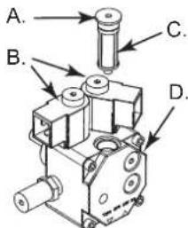
natural_image
Technical line drawing of a mechanical device with labeled component C (no text or symbols beyond label)natural_image
Line drawing of a handheld electronic device with coiled cable and ports (no text or symbols)COLLEGAMENTO DEL TERMOSTATO AMBIENTE

natural_image
Technical line drawing of a cable connector and mechanical assembly (no text or symbols)natural_image
Technical line drawing of a mechanical device with directional arrows indicating flow or movement (no text or symbols)RUOTA GIREVOLE CON FRENO

natural_image
Technical line drawing of a mechanical component with a curved wheel and mounting bracket (no text or symbols)natural_image
Line drawing of a rectangular box with vertical connectors and a base (no text or symbols)natural_image
Technical line drawing of a robotic device with wheels and control panels (no text or symbols)Abbildung 3

Abbildung 4
natural_image
Technical line drawing of a mechanical component with arrows indicating direction (no text or symbols)natural_image
Technical line drawing of a mechanical assembly with directional arrows indicating motion (no text or symbols)natural_image
Technical line drawing of a mechanical clamp or tool assembly (no text or symbols)A. Dichtungsringe,
B. Plastik- schale,
C. Filterelement,
natural_image
Line drawing of a mechanical device with labeled component C (no text or symbols beyond label)natural_image
Technical line drawing of a mechanical device with labeled component C (no text or symbols beyond label)natural_image
Line drawing of a handheld electrical contactor with coiled cable (no text or symbols)natural_image
Technical line drawing of a mechanical assembly with no visible text or symbolsnatural_image
Technical line drawing of a mechanical device with directional arrows indicating flow or movement (no text or symbols)DREHBARES RAD MIT BREMSE

natural_image
Technical line drawing of a mechanical component with a curved handle and mounting feet (no text or symbols)FEHLERSUCHE
natural_image
Line drawing of a rectangular box with a side panel, no text or symbols presentFigura 1 - Embalaje
EMBARQUE Y ALMACENAMIENTO
natural_image
Technical line drawing of a robotic device mounted on a platform (no text or symbols visible)Figura 2 - Encima el palet
Figura 3

Figura 4
natural_image
Technical line drawing of a mechanical component with arrows indicating features (no text or symbols)Figura 7 - Ganchos para levantar
DESPLAZAMIENTO
natural_image
Technical line drawing of a mechanical assembly with directional arrows indicating motion (no text or symbols)natural_image
Technical line drawing of a mechanical clamp or tool assembly (no text or symbols)A. Juntas de goma,

natural_image
Technical line drawing of a mechanical device with labeled component C (no text or symbols beyond label)Figura 12 - Tubo del quemador
natural_image
Technical line drawing of a mechanical device with labeled component C (no text or symbols present)Figura 14 - Disco llama-electrodos
A. Tubo del quemador, B. Tornillos tubo del quemador, C. Tornillos disco llama, D. Disco llama, E. Electrodos, F. Porta-boquillas, G. Boquilla, H. Tornillos
ACCESORIOS OPCIONALES TERMOSTATO AMBIENTE
natural_image
Line drawing of a handheld electronic device with coiled cable and ports (no text or symbols)natural_image
Technical diagram showing mechanical components connected by dashed arrows, no text or symbols presentnatural_image
Diagram of a mechanical device with directional arrows indicating flow or movement (no text or symbols)RUEDA APOYO
natural_image
Line drawing of a mechanical component with a circular head and mounting bracket (no text or symbols)natural_image
Line drawing of a rectangular box with horizontal lines and a base (no text or symbols)Figure 1 - Emballage
EMBALLAGE Y ENTREPOSAGE
natural_image
Technical line drawing of a mechanical robotic device with wheels and mounting base (no text or symbols)Figure 3

ALLUMAGE AVEC THERMOSTAT
natural_image
Technical line drawing of a mechanical component with arrows indicating features (no text or symbols)natural_image
Technical line drawing of a mechanical assembly with no visible text or symbolsnatural_image
Technical line drawing of a manual wire tool with multiple blades (no text or symbols)A. Garnitures,

natural_image
Line drawing of a mechanical device with labeled component C (no text or symbols beyond label)natural_image
Technical line drawing of a mechanical device with labeled component C (no text or symbols beyond label)natural_image
Line drawing of a handheld device with coiled cable and control panel (no text or symbols)CONNEXION DU DISPOSITIF DE CONTRÔLE
natural_image
Technical diagram showing mechanical assembly with no visible text or symbolsnatural_image
Technical line drawing of a mechanical component with directional arrows indicating flow or movement (no text or symbols)ROULETTE PIVOTANTE
natural_image
Line drawing of a mechanical component with a curved wheel and mounting bracket (no text or symbols)PRODUKTSOMSCHRIJVING
natural_image
Line drawing of a rectangular box with horizontal lines and a base frame (no text or symbols)natural_image
Technical line drawing of a mechanical device with wheels and mounting base (no text or symbols)Figuur 3

Figuur 5 - Knoppeni

HOE HET APPARAAT WERKT
INSCHAKELING MET DE THERMOSTAAT
TRANSPORT EN VERPLAATSING
natural_image
Technical line drawing of a mechanical component with arrows indicating features (no text or symbols)natural_image
Technical line drawing of a mechanical linkage assembly with directional arrows indicating motion (no text or symbols)natural_image
Technical line drawing of a mechanical clamp or tool assembly (no text or symbols)Figuur 9 - Positie open handvatten
natural_image
Line drawing of a mechanical device with labeled component C (no text or symbols present)ACCESSOIRES THERMOSTAAT

natural_image
Line drawing of a handheld electronic device with a coiled cable and two ports (no text or symbols)AANSLUITING VAN DE THERMOSTAAT
natural_image
Technical line drawing of a cable connector with internal components and directional arrows indicating assembly (no text or symbols)natural_image
Technical line drawing of a mechanical component with directional arrows indicating flow or movement (no text or symbols)natural_image
Line drawing of a mechanical component with a circular head and mounting bracket (no text or symbols)HERKENNING VAN DE MANKEMENTEN
natural_image
Line drawing of a rectangular box with visible internal divisions and support frame (no text or symbols)Figur 1 - Mballage
EMBALLAGE OG OPBEVARING
natural_image
Technical line drawing of a mechanical device with wheels and mounting base (no text or symbols)Figur 2 - På palle
INFORMATIONER VEDR∅RENDE SIKKERHEDEN
ADVARSEL

Figur 3

Figur 5 - Kontroller
natural_image
Technical line drawing of a mechanical component with arrows indicating motion or assembly (no text or symbols)natural_image
Technical line drawing of a mechanical linkage assembly with directional arrows indicating motion (no text or symbols)natural_image
Technical line drawing of a mechanical clamp or tool assembly (no text or symbols)A. O-ringe,
B. Plastik
bæger,
C. Filter
-element,
D. Bræn-
dstofventil
Figur 10 - Filter
RENG∅RING AF PUMPEFILTERET
natural_image
Technical line drawing of a mechanical device with labeled component C (no text or symbols present)natural_image
Line drawing of a handheld electrical device with coiled cable and two ports (no text or symbols)TILSLUTNING AF DEN OMGIVENDE TERMOSTAT
natural_image
Technical line drawing of a cable connector assembly with directional arrows indicating assembly steps (no text or symbols)natural_image
Technical line drawing of a mechanical component with directional arrows indicating flow or movement (no text or symbols)HJUL AF BREMSE
natural_image
Line drawing of a mechanical component with a circular head and mounting plate (no text or symbols)natural_image
Line drawing of a rectangular box with vertical connectors and a base (no text or symbols)natural_image
Technical line drawing of a robotic device with wheels and control panels (no text or symbols)Rysunek 3
Rysunek 4
natural_image
Technical line drawing of a mechanical component with arrows indicating features (no text or symbols)natural_image
Technical line drawing of a mechanical linkage assembly with directional arrows indicating motion (no text or symbols)natural_image
Technical line drawing of a mechanical clamp or tool assembly (no text or symbols)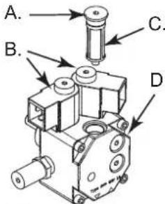
A. Ostona filtra pompy,
natural_image
Technical line drawing of a mechanical device with labeled component C (no text or symbols beyond label)natural_image
Line drawing of a handheld electronic device with a coiled cable and two ports (no text or symbols)PODŁĄCZANIE URZĄDZENIA STERUJĄCEGO
natural_image
Technical diagram showing a cable being inserted into a connector with two connectors, connected by dashed arrows indicating assembly or connection (no text or symbols present)natural_image
Technical line drawing of a mechanical component with directional arrows indicating flow or force (no text or symbols)KÓŁKO OBROTOWE Z HAMULCEM

natural_image
Line drawing of a mechanical component with wheels and mounting feet (no text or symbols)USTERKI I ICH PRAWDOPODOBNE PRZYCZYNY
natural_image
Line drawing of a rectangular box with vertical connectors and a base (no text or symbols)1 Zîmçjums - lepakojumâ
IEPAKOJUMA UN UZGLABÂSANA
natural_image
Technical line drawing of a mechanical device with wheels and a mounted base (no text or symbols)2 Zîmçjums - Uz paletes
DROSÎBAS INFORMÂCIJA
BRÍDINÂJUMS

3 Zimçjums

4 Zîmçjums
A. Degšanas kamera, B. Caurums ěeneratora pacelđanai, C. Degvielas filtrs vai uzsildîsanas filtrs (opcija), D. Degvielas padeve, E. Degvielas atgriëšana, F. Degvielas tvertnes våks, G. Kâjiňa vai ritenis (opcija), H. Degvielas lîmeňa indikators, I. Degđanas vienîbu bloks, L. Atstarotâjs, M. Degvielas novade, N. Degvielas tvertne, O. Rokturis ěeneratora pârvietođanai, P. Viras bloks, Q. Deglis, R. Noliekuma regulators
5 Zîmçjums - Vadîbas pogas

6 Zîmçjums - Degd'a elementi
A. Ventilâcijas atveres regulçtâjs, B. leslçgts/izslçgts poga ar apgaismojumu, C. leslçgts/izslçgts komutators atkarîbâ no izvçlçtâs jaudas (XL 9SR), D. Atkârtotâs palaidanas poga, E. Strâvas indikators, F. Degđa kaste, G. Termostata kontaktligzda, H. Degđa bloka skrüve, I. Sekundârâs ventilâcijas ierîce, L. Liesmas vadîbas ierîce, M. Transformators, N1. Sükňa spiediena regulçtâjs (XL 9ER), N2. Sükňa spiediena regulçtâjs (XL 9SR), O1. (XL 9ER) degvielas süknis, O2. (XL 9SR) degvielas süknis, P. Kondensators, Q. Motors, R. Degđa caurule, S. Degšanas galviñas regulçtâjs, T. Foto rezistors, U1. Elektriskais vârsts: 1° liesmas solis (XL 9ER-SR), U2. Elektriskais vârsts: 2° liesmas solis (XL 9SR)
DEGVIELA
BRÎDINÂJUMS: ěeneratora uzpildîdanai izmantojiet TIKAI petroleju vai dîzed'degvielu.
Ja tiks izmantota degviela ar piemaisijumiem, var:
•Tikt nobloícti degšanas filtrs vai sprausla.
- Uzkrâties oglekđa nogulas uz elektrodiem.
Pie zemâm temperatürâm izmantojiet netoksisko antifrîzu.
DARBÎBAS PRINCIPI
Degšanas procesam nepieciešamâ ventilâcija tiek nodrođinâta ar deglî iebûvçto ventilatoru. Gaiss iziet pa degđa uzmavu un savienojas ar degvielu, kas tiek izsmidzinâta zem augsta spiediena caur sprauslu. Degviela tiek sûknçta no degvielas tvertnes ar rotora sûkni, kas virza degvielu zem spiediena lîdz sprauslai, kura to tâlâk izsmidzina ârâ.
EKSPLUATÂCIJAS INSTRUKCIJAS
natural_image
Technical line drawing of a mechanical component with arrows indicating features (no text or symbols)7 Zîmçjums - Aizíeres iekârtas pacelđanai
PÂRVIETODANA
Pirms iekârtas pârvietodanas vai paceldanas pârliecinieties, ka ir aiztaisîti ciet degvielas tvertnes vâki (G Zîmcjums 3). Ėeneratoram ir jâbût aprîkotam ar riteni, lai to varçtu stumt kâ ratus. Gadîjumâ, ja riteňu nav, ir jâatbloíç vira (P Zîmcjums 4), kas atrodas uz viena no aizmugurçjiem balsteňiem. Pagrieziet rokturus no „stâvçđanas pozicijas,, (8 Zîmcjums) „transportçđanas pozicijâ” (9 Zîmcjums). Paceliet ěeneratoru tâ, lai tas balstítos uz diviem ârçjiem riteňiem.
natural_image
Technical line drawing of a mechanical assembly with no visible text or symbols8 Zimçjums - Rokturi ir salikti, „stâvçđanas pozícijá”
natural_image
Technical line drawing of a mechanical clamp or tool assembly (no text or symbols)9 Zîmçjums - Rokturi ir pacelti, „transportçđanas pozîcijâ”
BRÎDINÂJUMS: Pirms sâkt pârvietot iekârtu: izslçdziet to, ievçrojot sadad'as „ËENERATORA IZSLÇGSANA” norâdíjumus, atvienojiet no enerëijas avota, atvienojot vadu no kontaktligzdas un uzgaidiet, kamçr ćeners atdzisîs.
PROFILAKTISKAIS REMONTS
BRÍDINÁJUMS: Pirms remonts: izslçdziet to, ievçrojot sadad'as „ĚENERATORA IZSLÇGSANA” norâdījumus, atvienojiet no enerëijas avota, atvienojot vadu no kontaktligzdas un uzgaidiet, kamçr ěenerators atdzisîs.
Dîs sadad'as rekomendâcijas attiecîbâ uz profilaktiskâs apskates grafiku bûtîbâ ir orientçjođas, jo viss ir d'oti atkarîgs no tâ, cik tîra ir izmantojamâ degviela un vides, kurâs darbojas ěenerators: rekomendâcijas ir sniegtas, pieñemot, ka ěenerators darbojas labi vedinâmâs telpâs ar zemu putekđu koncentrâciju un tiek izmantota tîra degviela.
Pçc katrâm 50 ekspluatâcijas stundâm:
A. O-gredzeni,
B. Plastmasas vâciñd,
C. Filtrçjodais elements,
D. Degvielas ieplüdes/ izplüdes korpuss
10 Zîmçjums - Filtrs
SÜKÑA FILTRA TİRİDANA
- Noñemiet degda kasti (F Zîmcjums 5), lai tiktu pie degda sükna O (6 Zîmcjums).
- Noskrüvcjiet uzgriezni (A Zîmcjums 11), kas piestiprina filtrçjođo elementu pie sükňa.
- Iznemiet filtrcjodo elementu (C Zîmçjums 11).
• Kârtîgi izmazgâjiet ar petroleju. - levietojiet filtrcjodo elementu atpakad' un uzskrúvcjiet uzgriezni.
11 Zimçjums - Moded'u degd'a süknis

A. Uzgrieznis sükňa filtra stiprinášanai, B. Vienkártainais XL 9ER modeda elektriskais vårsts, dubultais XL 9SR modeda elektriskais vårsts,
C. Filtrs, D. Sūknis
DEGLA TİRİSANA
- Atskrūvçjiet skrūvi (H Zimçjums 5), kas stiprina degli (A Zimçjums 3) degdanas kamerā.
- Iznemiet degli ârâ (3 Zîmçjums).
- Izskrüvçjiet trîs skrüves (B Zîmçjums 12), ar kurâm ir stiprinâta degđa caurule (A Zîmçjums 12).
- Nošemiet cauruli.
- Izskrūvçjiet skrūvi (C Zîmcjums 13), ar kuru tiek stiprināti liesmas diska elektrodi un izvelciet sprauslas patronu (F Zîmcjums 14).
- Iztiriet liesmas disku (D Zimçjums 14) un elektrodus (E Zimçjums 14).
- Noskrūvçjiet sprauslu (G Zîmçjums 14) nost no tâs patronas (F Zîmçjums 14), iztīriet to vai nomainiet, ja nepiecieđams.
- lelieciet sprauslu (G Zîmçjums 14) atpakad patronâ.
- Piemontçijet atpakad' liesmas diska un elektrodu bloku, uzmanoties, lai starp elektrodiem ir noregulçts pareizs attâlums (sk. 14 Zîmcjumu).
natural_image
Technical line drawing of a mechanical device with labeled component C (no text or symbols beyond label)natural_image
Technical line drawing of a mechanical device with labeled component C (no text or symbols present)13 Zimçjums - Liesmas diska un elektrodu bloka noñemđana

14 Zîmçjums - Sprauslas un elektrodu attâlumi
A. Degd'a caurule, B. Degd'a caurules skrûve, C. Screw Flame disk, D. Flame disk, E. Electrodes, F. Tube, G. Nozzle, H. Screw
PIEDERUMI
THERMOSTAT

natural_image
Line drawing of a handheld electrical device with coiled cable and ports (no text or symbols)DROĐÎBAS IERÎCES SAVIENOSANA
natural_image
Technical line drawing of a mechanical assembly with no visible text or symbolsnatural_image
Technical line drawing of a mechanical device with directional arrows indicating flow or movement (no text or symbols)RITENIS AR BREMZÇM
natural_image
Technical line drawing of a mechanical frame with a wheel and mounting bracket (no text or symbols)KLÜMES UN TO IESPEJAMIE CELOÑI
BRÎDINÂJUMS: Pirms såkt jebkâdas remontdarbîbas: ir jâapstådina iekârta saskaňâ ar sadad'â „ÊENERATORA IZSLÇGDANA” norâdîtajâm instrukcijâm, jâatvieno barošanas vads no strâvas un jâuzgaida, kamçr ̈enerators atdzisîs.
natural_image
Line drawing of a rectangular box with vertical connectors and a base (no text or symbols)natural_image
Technical line drawing of a mechanical device with wheels and mounting base (no text or symbols)Joonis 2 - Mudeli estvaade
PÕHILISED OHUTUSNÕUDED HOIATUS
Joonis 3

Joonis 4
natural_image
Technical line drawing of a mechanical component with arrows indicating features (no text or symbols)natural_image
Technical line drawing of a mechanical clamp or bracket assembly with directional arrows indicating motion (no text or symbols)natural_image
Technical line drawing of a mechanical clamp or tool assembly (no text or symbols)A. O-gredzeni,
B. Plastmasas vâciňd,
C. Filtrçjodais elements,
D. Degvielas ieplüdes/ izplüdes korpuss
Joonis 10 - Soojendi filter
PUMPA FILTRI PUHASTAMINE

A. Nut for blocking the pump filter, B. Single electrovalve for XL 9ER doble electr. for XL 9SR C. Filter, D. Pump
natural_image
Technical line drawing of a mechanical device with labeled component C (no text or symbols beyond label)Joonis 14 - Disk flame
A. Toru, B. Kruvi toru, C. Kruvi leegiketas, D. Leegiketas, E. Elektrooodid, F. Toru, G. Düüs, H. Kruvi
TARVIKUD
TERMOSTAAT
natural_image
Line drawing of a handheld electronic device with coiled cable and ports (no text or symbols)KONTROLLSEADISE KÜLGEÜHENDAMINE
natural_image
Technical line drawing of a cable connector and mechanical assembly (no text or symbols)natural_image
Technical line drawing of a mechanical component with directional arrows indicating flow or movement (no text or symbols)PIDURIGA VARUSTATUD PÖÖRLEV RATAS
natural_image
Line drawing of a mechanical component with a circular head and mounting bracket (no text or symbols)TÖRKED JA NENDE VÕIMALIKUD PÕHJUSED
natural_image
Line drawing of a rectangular box with visible internal structure and two side supports (no text or symbols)Obrázek 1
natural_image
Technical line drawing of a mechanical robotic device mounted on a platform (no text or symbols visible)Obrázek 2
INFORMACE TÝKAJÍCÍ SE BEZPEČNOSTI OBSLUHY VAROVÁNÍ
UPOZORNĚNÍ

Obrázek 3

Obrázek 4
natural_image
Technical line drawing of a mechanical component with arrows indicating features (no text or symbols)natural_image
Technical line drawing of a mechanical device with no visible text or symbolsnatural_image
Line drawing of a manual tool with two metal cutting tips (no text or symbols)A. O-kroužek,
B. Víčko,
C. Filtr,
D. Těleso filtru
Obrázek 10 - Filtr
ČIŠTĚNÍ PALIVOVÉHO ČERPADLA
natural_image
Technical line drawing of a mechanical device with labeled component C (no text or symbols present)natural_image
Line drawing of a handheld electrical device with coiled cable and ports (no text or symbols)PŘIPOJENÍ OVLÁDACÍHO ZAŘÍZENÍ
natural_image
Technical diagram showing mechanical assembly with no visible text or symbolsnatural_image
Technical line drawing of a mechanical component with directional arrows indicating motion (no text or symbols)POJEZDOVÁ KOLA S BRZDOU

natural_image
Technical line drawing of a mechanical component resembling a wheel or pulley (no text or symbols)natural_image
Line drawing of a rectangular box with horizontal connectors and a wooden base (no text or symbols)natural_image
Technical line drawing of a robotic device mounted on a platform (no text or symbols visible)2 Ábra - A raklapon
FIGYELMEZTETÉS
IGYELMEZTETÉS

3 Ábra

4 Ábra
natural_image
Technical line drawing of a mechanical component with arrows indicating direction (no text or symbols)7 Ábra - Hooks
SZÁLLÍTÁS
natural_image
Technical line drawing of a mechanical assembly with no visible text or symbolsnatural_image
Technical line drawing of a mechanical clamp or tool assembly (no text or symbols)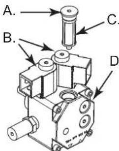
natural_image
Technical line drawing of a mechanical device with labeled component C (no text or symbols present)natural_image
Line drawing of a handheld electrical device with coiled cable and two ports (no text or symbols)natural_image
Technical line drawing of a mechanical assembly with rollers and housing components (no text or symbols)natural_image
Technical line drawing of a mechanical component with directional arrows indicating flow or movement (no text or symbols)FÉKKEL ELLÁTOTT FORGÓKERÉK
natural_image
Line drawing of a mechanical component with a curved wheel and mounting bracket (no text or symbols)MEGHIBÁSODÁSOK ÉS VALÓSZÍNÚ OKAI
natural_image
Line drawing of a rectangular box with vertical connectors and a base (no text or symbols)Figura 1 - Impachetat
TRANSPORT SI DEPOZITARE
natural_image
Technical line drawing of a robotic lawn mower mounted on a platform (no text or symbols)Figura 2 - Pe palet
INFORMATIILE LEGATE DE EXPLOATAREA ÎN CONDIȚII DE SIGURANTĂ
AVERENT

Figura 3

Figura 4
natural_image
Technical line drawing of a mechanical component with arrows indicating features (no text or symbols)natural_image
Technical line drawing of a mechanical assembly with no visible text or symbolsnatural_image
Technical line drawing of a mechanical clamp or tool assembly (no text or symbols)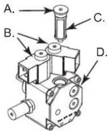
natural_image
Technical line drawing of a mechanical device with labeled component C (no text or symbols beyond label)natural_image
Technical line drawing of a mechanical device with labeled component C (no text or symbols present)natural_image
Line drawing of a handheld device with coiled cable and adjustment knob (no text or symbols)CONECTAREA DISPOZITIVULUI DE COMANDĂ
natural_image
Technical line drawing of a mechanical assembly with no visible text or symbolsnatural_image
Technical line drawing of a mechanical component with directional arrows indicating flow or movement (no text or symbols)ROATĂ CU SISTEM DE BLOCARE
natural_image
Technical line drawing of a mechanical component with a circular head and mounting feet (no text or symbols)EVENTUALE DEFECTE ŞI CAUZELE POSIBILE ALE ACESTORA
natural_image
Line drawing of a rectangular box with a flat base and two vertical straps (no text or symbols)natural_image
Technical line drawing of a mechanical robotic device mounted on a platform (no text or symbols visible)Фигура 3

Фигура 4
natural_image
Technical line drawing of a mechanical component with arrows indicating features (no text or symbols)Фигура 7
ПРЕМЕСТВАНЕ
natural_image
Technical line drawing of a mechanical linkage assembly with directional arrows indicating motion (no text or symbols)natural_image
Technical line drawing of a mechanical clamp or tool assembly (no text or symbols)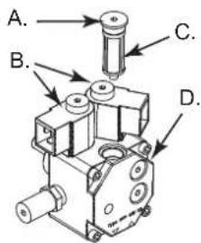
natural_image
Line drawing of a mechanical device with labeled component C (no text or symbols beyond label)Фигура 12 - Демонтаж на горелката

natural_image
Technical line drawing of a mechanical device with labeled component C (no text or symbols beyond label)natural_image
Line drawing of a handheld device with coiled cable and two circular ports (no text or symbols)ТЕРМОРЕЗИСТОР
natural_image
Technical line drawing of a mechanical assembly with no visible text or symbolsnatural_image
Technical line drawing of a mechanical component with directional arrows indicating flow or movement (no text or symbols)СИСТЕМА ПРЕДПАЗВАЩА ОТ НАКЛАНЯНЕ

natural_image
Line drawing of a mechanical device with a handle and wheels (no text or symbols)natural_image
Line drawing of a rectangular box with visible internal divisions and support frame (no text or symbols)natural_image
Technical line drawing of a robotic arm mounted on a platform (no text or symbols)Рисунок 3

Рисунок 4
natural_image
Technical line drawing of a mechanical component with arrows indicating motion or assembly (no text or symbols)natural_image
Technical line drawing of a mechanical assembly with directional arrows indicating motion (no text or symbols)natural_image
Technical line drawing of a mechanical clamp or tool assembly (no text or symbols)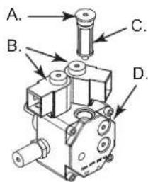
natural_image
Line drawing of a mechanical device with labeled component C (no text or symbols beyond label)natural_image
Technical line drawing of a mechanical device with labeled component C (no text or symbols present)natural_image
Line drawing of a handheld electrical device with coiled cable and two ports (no text or symbols)natural_image
Technical line drawing of a mechanical assembly with no visible text or symbolsnatural_image
Technical line drawing of a mechanical component with directional arrows indicating flow or movement (no text or symbols)natural_image
Technical line drawing of a mechanical component with a curved wheel and mounting bracket (no text or symbols)natural_image
Line drawing of a rectangular box with vertical connectors and a base (no text or symbols)natural_image
Technical line drawing of a mechanical surveying instrument mounted on a wooden base (no text or symbols)Kuva 2 - Lavalla
TURVALLISUUTEEN LIITTYVÄÄ TIETOA VAROITUS

Kuva 3

Kuva 4
Kuva 5 - Komennot

natural_image
Technical line drawing of a mechanical component with arrows indicating motion or force direction (no text or symbols)A. Tiivisteet,
B. Lasi, C.
natural_image
Technical line drawing of a mechanical device with labeled component C (no text or symbols beyond label)natural_image
Line drawing of a handheld electronic device with coiled cable and two ports (no text or symbols)HUONETERMOSTAATIN LIITÄNNÄT
natural_image
Technical line drawing of a cable connector with internal components and directional arrows indicating assembly (no text or symbols)natural_image
Technical line drawing of a mechanical component with directional arrows indicating flow or movement (no text or symbols)KÄÄNTYVÄ RENGAS JARRULLA

natural_image
Line drawing of a mechanical component with a curved handle and mounting bracket (no text or symbols)natural_image
Line drawing of a rectangular box with visible internal divisions and support frame (no text or symbols)FIGUR 1 - Emballasje
EMBALLASJE OG OPPBEVARING
natural_image
Technical line drawing of a mechanical robotic device mounted on a base (no text or symbols visible)Figur 2 - På pall
SIKKERHETSINFORMASJON ADVARSEL
Figur 3

Figur 5 - Kontroller
SLÅ PÅ MED ROMTERMOSTAT
natural_image
Technical line drawing of a mechanical component with arrows indicating features (no text or symbols)Figur 7 - Festeboltene
HÄNDTERING
Varmeovnen kan leveres med svinghjul (G Fig. 3). I dette tilfellet, hvis underlaget tillater det, skyv ovnen som en vogn. Hvis apparatet ikke er utstyrt med svinghjul, skal stiften (P Fig. 4) som finnes på en av ovnens sidestenger frakobles. Sett håndtakene ned i »hvileposisjon« (Fig. 8). Vri håndtakene til "hånderingsposisjon" (Fig. 9). Løft varmeovnen og flytt den ved å la den gli på hjulene foran.
natural_image
Technical line drawing of a mechanical assembly with directional arrows indicating motion (no text or symbols)natural_image
Technical line drawing of a mechanical clamp or tool assembly (no text or symbols)A. Pakninger,
B. Beger,
C. Filterelement,
A. Mutter til filterfeste, B. Enkel magnetventil for XL 9ER, dobbel for XL9 SR, C.Filter, D. Pumpedel.
Figur 11 - Brennerpumpe
RENGJ∅RING AV BRENNER
natural_image
Technical line drawing of a mechanical device with labeled component C (no text or symbols beyond label)Figur 13 - Demontering enhet flammeplate-elektroder
Figur 14 - Avstander elektroder dyse
A. Rør, B. Skrue rør, C. Skrue enhet flammeplate, D. Flammeplate, E. Elektroder, F. Dyseholder, G. dyse, H. Skrue.
TILLEGGSUTSTYR
ROMTERMOSTAT

natural_image
Line drawing of a handheld electrical device with coiled cable and control panel (no text or symbols)KOBLING TIL ROMTERMOSTAT
natural_image
Technical diagram showing mechanical components connected to a coiled cable, with dashed arrows indicating assembly or alignment (no text or symbols present)natural_image
Technical line drawing of a mechanical component with directional arrows indicating flow or movement (no text or symbols)SVINGHJUL MED BREMS

natural_image
Technical line drawing of a mechanical frame with a curved handle and mounting feet (no text or symbols)FEILS∅K
natural_image
Line drawing of a rectangular box with vertical connectors and a base frame (no text or symbols)natural_image
Technical line drawing of a mechanical device with wheels and mounting base (no text or symbols)Cypem 3

Cypem 4
natural_image
Technical line drawing of a mechanical component with arrows indicating direction (no text or symbols)natural_image
Technical line drawing of a mechanical assembly with no visible text or symbolsnatural_image
Technical line drawing of a mechanical clamp or tool assembly (no text or symbols)
natural_image
Technical line drawing of a mechanical device with labeled component C (no text or symbols beyond label)natural_image
Technical line drawing of a mechanical device with labeled component C (no text or symbols beyond label)natural_image
Line drawing of a handheld electronic device with a coiled cable and two circular ports (no text or symbols)natural_image
Technical line drawing of a cable connector assembly with internal components (no text or symbols)natural_image
Technical line drawing of a mechanical component with directional arrows indicating flow or movement (no text or symbols)natural_image
Technical line drawing of a mechanical component with a curved handle and mounting bracket (no text or symbols)natural_image
Abstract blue line drawing with no text or symbolsPastrengo, 2023
▶ en - DISPOSAL OF THE PRODUCT
-This product has been designed and manufactured with top-quality materials and components, which can be re-cycled and re-used. -When a crossed-wheely bin symbol is attached to the product, it means that the product is protected by the, 2012/19/UE European Directive.
-Please obtain information regarding the local differentiated collection system for electrical and electronic products.
-Respect local Standards in force and do not dispose of old products as normal domestic waste. Correct disposal of the product helps to prevent possible negative consequences for health, the environment and mankind.
▶pl - UTYLIZACJA PRODUKTU
▶ Iv - PRODUKTA IZNĪCINĀŠANA
natural_image
Abstract geometric composition with yellow and black blocks (no text or symbols)Dantherm S.p.A.
Via Gardesana 11
37010 Pastrengo (VR)
Italy
t.: +39 045 6770533
e.: info.it@danthermgroup.com

DOWNLOAD CATALOGUE

SEND US YOUR FEEDBACK

REGISTER FOR 3-YEAR WARRANTEE