
DCSNP2142 - Snow blower DEWALT - Free user manual and instructions
Find the device manual for free DCSNP2142 DEWALT in PDF.

User questions about DCSNP2142 DEWALT
0 question about this device. Answer the ones you know or ask your own.
Ask a new question about this device
Download the instructions for your Snow blower in PDF format for free! Find your manual DCSNP2142 - DEWALT and take your electronic device back in hand. On this page are published all the documents necessary for the use of your device. DCSNP2142 by DEWALT.
USER MANUAL DCSNP2142 DEWALT
Single Stage Battery Powered Snow Blower
English (original instructions) 1
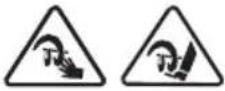
Definitions: Safety Alert Symbols and Words
This instruction manual uses the following safety alert symbols and words to alert you to hazardous situations and your risk of personal injury or property damage.

DANGER: Indicates an imminently hazardous situation which, if not avoided, will result in death or serious injury

WARNING: Indicates a potentially hazardous situation which, if not avoided, could result in death or serious injury.

CAUTION: Indicates a potentially hazardous situation which, if not avoided, may result in minor or moderate injury.

(Used without word) Indicates a safety related message.
NOTICE: Indicates a practice not related to personal injury which, if not avoided, may result in property damage.
natural_image
Line drawing of a lawn mower with attached motors and wheels (no text or symbols)
WARNING!
Read all safety warnings and all instructions. Failure to follow the warnings and instructions may result in electric shock, fire, and/or serious injury.
NOTE: This Operator's Manual covers several models. Features may vary by model. Not all features in this manual are applicable to all models and the model depicted may differ from yours.
If you have any questions or comments about this or any DEWALT tool, call us toll free at: 1-855-971-1123.
SAFE OPERATION PRACTICES
WARNING

This symbol points out important safety instructions which, if not followed, could endanger the personal safety and/or property of yourself and others. Read and follow all instructions in this manual before attempting to operate this machine. Failure to comply with these instructions may result in personal injury.
When you see this symbol, HEED ITS WARNING!
DANGER
This machine was built to be operated according to the safe operation practices in this manual. As with any type of power equipment, carelessness or error on the part of the operator can result in serious injury. This machine is capable of amputating fingers, hands, toes and feet and throwing debris. Failure to observe the following safety instructions could result in serious injury or death.
TRAINING
- Read, understand, and follow all instructions on the machine and in the manual(s) before attempting to assemble and operate. Keep this manual in a safe place for future and regular reference and for ordering replacement parts.
- Be familiar with all controls and their proper operation. Know how to stop the machine and disengage them quickly.
- Never allow children under 14 years of age to operate this machine. Children 14 and over should read and understand the instructions and safe operation practices in this manual and on the machine and be trained and supervised by an adult.
- Never allow adults to operate this machine without proper instruction.
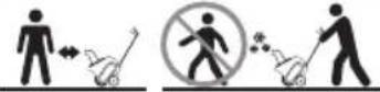
- Thrown objects can cause serious personal injury. Plan your snow-blowing pattern to avoid discharge of material toward roads, bystanders and the like.
- Keep bystanders, pets and children at least 75 feet from the machine while it is in operation. Stop machine if anyone enters the area.
PREPARATION
Thoroughly inspect the area where the equipment is to be used. Remove all doormats, newspapers, sleds, boards, wires and other foreign objects, which could be tripped over or thrown by the machine.
- Always wear safety glasses or eye shields during operation and while performing an adjustment or repair to protect your eyes. Thrown objects which ricochet can cause serious injury to the eyes.
- Do not operate without wearing adequate winter outer garments. Do not wear jewelry, long scarves or other loose clothing, which could become entangled in moving parts. Wear footwear which will improve footing on slippery surfaces.
- Disengage all control levers before starting the motor.
- Never attempt to make any adjustments while motor is running, except where specifically recommended in the operator's manual.
OPERATION
- Do not put hands or feet near rotating parts, in the auger housing or chute assembly. Contact with the rotating parts can amputate hands and feet.
- The auger control bail is a safety device. Never bypass its operation. Doing so makes the machine unsafe and may cause personal injury.
- The auger control bail must operate easily in both directions and automatically return to the disengaged position when released.
- Never operate with a missing or damaged guard or chute assembly. Keep all guards and safety devices in place and in working order.
- The handle sensor is a safety device. Ensure the handle is locked in the upright position and that the nub of the left handle lever engages with the slot of the handle sensor.
- Do not operate machine while under the influence of alcohol or drugs.
- Do not use on graveled surface. Exercise extreme caution and disengage the auger crossing gravel surfaces. Stay alert for hidden hazards or traffic.
- Exercise caution when changing direction and while operating on slopes. Do not operate on steep slopes.
- Plan your snow-blowing pattern to avoid discharge towards windows, walls, cars etc. Thus, avoiding possible property damage or personal injury caused by a ricochet.
- Never direct discharge at children, bystanders and pets or allow anyone in front of the machine.
- Do not overload machine capacity by attempting to clear snow at too fast of a rate. It will perform better and safer at the rate for which it was designed.
- Never operate this machine without good visibility or light. Don't Overreach. Always be sure of your footing and balance. Keep a firm hold on the handles. Walk, never run.
- Release auger control bail to disengage power to the auger when transporting or not clearing snow.
SAFE OPERATION PRACTICES
- Never operate machine at high transport speeds on slippery surfaces. Look down and behind and use care when backing up.
- After striking a foreign object or if the machine should start to vibrate abnormally, stop the motor, remove the safety key. Inspect thoroughly for damage. Repair any damage before starting and operating.
- Disengage the auger control bail, stop motor, and remove the safety key before you leave the operating position (behind the handles). Wait until the auger comes to a complete stop before unclogging the chute assembly, making any adjustments, or inspections.
- Never put your hand in the discharge or collector openings. Always use a clean-out tool to unclog the discharge opening. Disengage the auger control bail, stop motor, and remove the safety key. Remain behind handles until all moving parts have stopped before unclogging.
- Use only attachments and accessories approved by the manufacturer (e.g. wheel weights, tire chains, cabs etc.). The use of an unapproved accessory or attachment may increase the risk of injury.
- If situations occur which are not covered in this manual, use care and good judgment. Contact Customer Support for assistance and the name of your nearest servicing dealer.
CLEARING A CLOGGED DISCHARGE CHUTE
Hand contact with the rotating impeller or auger inside the discharge chute is the most common cause of injury associated with snow blowers. Never use your hand to clean out the discharge chute.
To clear the chute:
- SHUT THE Motor OFF!
- Remove the safety key.
- Wait 10 seconds to be sure the impeller or auger has stopped rotating.
- Always use a clean-out tool, not your hands.
- Never tamper with safety devices. Check their proper operation regularly. Refer to the maintenance and adjustment sections of this manual.
- Before cleaning, repairing, or inspecting machine, disengage the auger control bail, stop the motor, remove the safety key and remove battery(ies). Wait until the auger comes to a complete stop.
-
Check bolts and screws for proper tightness at frequent intervals to keep the machine in safe working condition. Also, visually inspect machine for any damage.
-
Snow blower shave plates are subject to wear and damage. For your safety protection, frequently check all components and replace with original equipment manufacturer's (OEM) parts only. Use of parts which do not meet the original equipment specifications may lead to improper performance and compromise safety!
- Check control levers periodically to verify they engage and disengage properly and adjust, if necessary. Refer to the adjustment section in this operator's manual for instructions.
- Maintain or replace safety and instruction labels, as necessary.
- Prior to storing, run machine a few minutes to clear snow from machine and prevent freeze up of auger.
- Store Idle Snow Blowers Indoors – When not in use, snow blowers should be stored indoors in a dry, locked-up place with the safety key removed and out of reach of children.
- According to the Consumer Products Safety Commission (CPSC), a snow blower has an Average Useful Life of six (6) years. At the end of the Average Useful Life have the machine inspected annually by an authorized service dealer to ensure that all mechanical, electrical, and safety systems are working properly and not worn excessively. Failure to do so can result in accidents, serious injuries or death.
DO NOT MODIFY SNOW BLOWER SPEED
To avoid serious injury of death, do not modify snow blower speed in any way. Tampering with operating speed can lead to unsafe operating conditions.
GENERAL ELECTRIC SAFETY
- Do not expose the snow blower to rain or wet conditions.
- Do not handle the snow blower with wet hands.
- Wear rubber boots when operating the snow mover.
- Avoid dangerous environments. Do not operate the unit in the rain, in wet conditions or on wet surfaces. Moisture is a shock hazard.
- To reduce the risk of electric shock, avoid body contact with grounded conductors, such as metal pipes or wire fences.
- Do not operate the snow blower in explosive atmospheres, such as in the presence of flammable liquids, gases or dust.
The battery pack is not fully charged out of the carton. Before using the battery pack and charger, read the safety instructions below and then follow charging procedures outlined below. When ordering replacement battery packs, be sure to include the catalog number and voltage.
SAFE OPERATION PRACTICES
IMPORTANT SAFETY INSTRUCTIONS FOR ALL BATTERY PACKS

WARNING
Read all safety warnings, instructions and cautionary markings for the battery pack, charger and product. Failure to follow the warnings and instructions may result in electric shock, fire and/or serious injury.
- Do not charge or use the battery pack in explosive atmospheres, such as in the presence of flammable liquids, gases or dust. Inserting or removing the battery pack from the charger may ignite the dust or fumes.
- When battery pack is not in use, keep it away from other metal objects, like paper clips, coins, keys, nails, screws or other small metal objects, that can make a connection from one terminal to another. Shorting the battery terminals together may cause burns or a fire.
- NEVER force the battery pack into the charger. Do not modify the battery pack in any way to fit into a non-compatible charger as battery pack may rupture causing serious personal injury.
- Charge the battery packs only in original equipment manufacturer chargers.
- Do not splash or immerse in water or other liquids.
- Do not store or use the tool and battery pack in locations where the temperature may reach or exceed 104^ F ( 40^ C) (such as outside sheds or metal buildings in summer). For best life store battery packs in a cool, dry location.
- Do not incinerate the battery pack even if it is severely damaged or is completely worn out. The battery pack can explode in a fire. Toxic fumes and materials are created when lithium-ion battery packs are burned.
- If battery contents come into contact with the skin, immediately wash area with mild soap and water. If battery liquid gets into the eye, rinse water over the open eye for 15 minutes or until irritation ceases. If medical attention is needed, the battery electrolyte is composed of a mixture of liquid organic carbonates and lithium salts.
- Contents of opened battery cells may cause respiratory irritation. Provide fresh air. If symptoms persist, seek medical attention.

WARNING
Burn hazard. Battery liquid may be flammable if exposed to spark or flame.

WARNING
Fire hazard. Never attempt to open the battery pack for any reason. If the battery pack case is cracked or damaged, do not insert into the charger. Do not crush, drop or damage the battery pack. Do not use a battery pack or charger that has received a sharp blow, been dropped, run over or damaged in any way (e.g., pierced with a nail, hit with a hammer, stepped on). Damaged battery packs should be returned to the service center for recycling.
IMPORTANT SAFETY INSTRUCTIONS FOR ALL BATTERY CHARGERS

WARNING
Read all safety warnings, instructions and cautionary markings for the battery pack, charger and product. Failure to follow the warnings and instructions may result in electric shock, fire and/or serious injury.
- Do not attempt to charge the battery pack with any chargers other than an original manufacturer charger. Original manufacturer charger and battery pack are specifically designed to work together.
- These chargers are not intended for any uses other than charging original manufacturer rechargeable batteries. Any other uses may result in risk of fire, electric shock or electrocution.
- Do not expose the charger to rain or snow.
- Pull by the plug rather than the cord when disconnecting the charger. This will reduce the risk of damage to the electric plug and cord.
- Make sure that the cord is located so that it will not be stepped on, tripped over or otherwise subjected to damage or stress.
- Do not use an extension cord unless it is absolutely necessary. Use of improper extension cord could result in risk of fire, electric shock or electrocution.
- When operating a charger outdoors, always provide a dry location and use an extension cord suitable for outdoor use. Use of a cord suitable for outdoor use reduces the risk of electric shock.
SAFE OPERATION PRACTICES
- An extension cord must have adequate wire size (AWG or American Wire Gauge) for safety. The smaller the gauge number of the wire, the greater the capacity of the cable, that is, 16 gauge has more capacity than 18 gauge. An undersized cord will cause a drop in line voltage resulting in loss of power and overheating. When using more than one extension to make up the total length, be sure each individual extension contains at least the minimum wire size. The following table shows the correct size to use depending on cord length and nameplate ampere rating. If in doubt, use the next heavier gauge. The lower the gauge number, the heavier the cord.
MINIMUM WIRE SIZE FOR EXTENSION CORDS FOR 120 VOLT APPLIANCES USING 0-6 AMPS
| Cord Length (ft.) | 25 | 50 | 100 | 150 |
| Wire Size (AWG) 18 | 16 16 14 |
- Do not place any object on top of the charger or place the charger on a soft surface that might block the ventilation slots and result in excessive internal heat. Place the charger in a position away from any heat source. The charger is ventilated through slots in the top and the bottom of the housing.
- Do not operate the charger with a damaged cord or plug - have them replaced immediately.
- Do not operate the charger if it has received a sharp blow, been dropped or otherwise damaged in any way. Take it to an authorized service center.
- Do not disassemble the charger; take it to an authorized service center when service or repair is required. Incorrect reassembly may result in a risk of electric shock, electrocution or fire.
- Disconnect the charger from the outlet before attempting any cleaning. This will reduce the risk of electric shock. Removing the battery pack will not reduce this risk.
- NEVER attempt to connect two (2) chargers together.
- The charger is designed to operate on standard 120V household electrical power. Do not attempt to use it on any other voltage.
WARNING
Shock hazard. Do not allow any liquid to get inside the charger. Electric shock may result.
WARNING
Burn hazard. Do not submerge the battery pack in any liquid or allow any liquid to enter the battery pack. Never attempt to open the battery pack for any reason. If the plastic housing of the battery pack breaks or cracks, return to a service center for recycling.
CAUTION
Burn hazard. To reduce the risk of injury, charge only original manufacturer rechargeable battery packs. Other types of batteries may overheat and burst resulting in personal injury and property damage.
CAUTION
Under certain conditions, with the charger plugged into the power supply, the charger can be shorted by foreign material. Foreign materials of a conductive nature, such as, but not limited to, grinding dust, metal chips, steel wool, aluminum foil or any buildup of metallic particles should be kept away from the charger cavities. Always unplug the charger from the power supply when there is no battery pack in the cavity. Unplug the charger before attempting to clean.
DISPOSING OF DAMAGED OR WORN-OUT BATTAROUTS Call2Recycle
The following toxic and corrosive material is used in unit's battery:
LITHIUM-ION, a toxic material.
Since 1994, Call2Recycle has diverted more than 75 million pounds of rechargeable batteries from local landfills and established a network of 30,000 recycling drop-off locations. More than 200 battery and/or product manufacturers, Call2Recycle Industry Stewards, have united to ensure that batteries are responsibly recycled when they reach their end of life and fund the program that is operated by Call2Recycle, Inc. 501(c)4 nonprofit public service organization.
To prevent contamination of the environment, contact your local waste disposal agency for specific instructi before disposing of damaged or worn-out lithium-ion
batteries. Take batteries to a local recycling and/or
disposal center, certified for lithium-ion battery disposal.
To locate the nearest recycling center, please call 1-800-822-8837.
FCC STATEMENT
Changes or modifications not expressly approved by the
Do not use broken or cracked batteries, even if there isn't party responsible for compliance could void the user's leakage. Replace damaged or worn-out batteries with authority to operate the equipment.
new batteries. DO NOT ATTEMPT TO REPAIR BATTERIES!
Repair attempts may result in severe personal injury, to explosion or electrical shock.
NOTE: This equipment has been tested and found to comply due. The limits for a Class B digital device, pursuant to part
with the limits for a Class B digital device, pursuant to part 15 of the FCC Rules. These limits are designed to provide
Reasonable protection against harmful interference in a
To avoid personal injury and damage to the environmen
- Do not attempt to remove or destroy any of the battery components. Do not open or mutilate the battery. If a develops, released electrolytes are corrosive and toxic not get the solution in your eyes or on your skin, and swallow it.
residential installation. This equipment generates, uses and canadiate radio frequency energy and, if not installed and used in accordance with the instructions, may cause harmful interference to radio communications. However, there is no guarantee that interference will not occur in a particular
-
Do not dispose of the battery in the regular househe
-
Do not dispose of the battery in a fire. The cell may be
-
Do not dispose of the battery where it will become waste landfill or municipal solid waste stream.
installation. If this equipment does cause harmful interference and crash. radio or television reception, which can be determined by turn explode.
the equipment off and on, the user is encouraged to try to cor.
-
Cover the battery terminals with heavy-duty adhesive
-
Dispose of the battery according to local, state and fee regulations.
- Reorient or relocate the receiving antenna.
ve tape.
- Dispose of the battery promptly.
About Call2Recycle Battery Seals
- Increase the separation between the equipment and receive ederal
- Connect the equipment into an outlet on a circuit different from that to which the receiver is connected.
- Consult the dealer or an experienced radio/TV technician for help.
Call2Recycle's industry steward program helps battery and product manufacturers
fulfill recycling requirements in the U.S. and
Canada, including compliance with extensive state, provincial and federal regulations, such
as the Mercury-Containing and Rechargeable
Battery Act (The Battery Act). Call2Recycle® Licensees/Industry
Stewards, participating battery and product manufacturers and marketers, purchase the rights to imprint the Call2Recycle Battery Seals on their rechargeable batteries and products.
When you see the Call2Recycle Battery Seal, you can feel confident knowing that your battery or product can be safely and responsibly recycled.
SAFETY SYMBOLS
This page depicts and describes safety symbols that may appear on this snow blower. Read, understand, and follow all instructions on the snow blower before attempting to assemble and operate.
| Symbol Description | |
 OPESymbol.com OPESymbol.com | DANGER – READ OPERATOR’S MANUAL: Read, understand and follow all the safety rules and instructions in the manual(s) and on the snow blower before attempting to operate this snow blower. Failure to comply with this information may result in personal injury or death. Keep this manual in a safe location for future and regular reference. Using a Smart Phone, scan the QR code symbol to learn more information concerning the warnings contained on this snow blower. You can also go to www.OPESymbol.com for more information. |
 | DANGER – AVOID AMPUTATION INJURY, DISCHARGE CHUTE: Do not put hands near or into the discharge chute while the motor is running. Contact with the rotating impeller or auger can amputate fingers and hands. Stop motor and remove safety key and wait until all moving parts have stopped rotating. Always use clean-out tool to clear the discharge chute, never use your hand. |
 | CAUTION – THROWN OBJECT: Use for snow removal only. |
 | WARNING — THROWN OBJECT/ENTANGLEMENT: Do not operate the snow blower without the guards and discharge chute installed. |
 | DANGER — AVOID THROWN OBJECT INJURY: Do not walk in front of running machine. Do not direct discharge at bystanders. |
 | DANGER — ROTATING BLADES: To reduce the risk of injury, keep hands and feet away. Do not operate unless discharge chute is in its proper place. If damaged, replace immediately. |
 | DANGER – AVOID AMPUTATION INJURY, AUGER HOUSING: Do not put hands or feet near or into the auger housing while the motor is running. Contact with the auger can amputate fingers, hands, toes and feet. |
 | WARNING — ELECTRIC SHOCK: Never douse or hose the snow blower with water. |
 | WARNING — ELECTRIC SHOCK: Remove the battery before storing or attempting any service. |
WARNING
Your Responsibility—Restrict the use of this power machine to persons who read, understand and follow the warnings and instructions in this manual and on the machine - SAVE THESE INSTRUCTIONS!
BATTERIES & CHARGERS
The battery pack is not fully charged out of the carton. Charging a Battery
using the battery pack and charger, read the safety instructions
in the Safe Operation Practices section and then follow charging procedures outlined in this section. When ordering replacement battery packs, be sure to include the catalog number and
voltage.
Important Charging Notes
NOTE: To ensure maximum performance and life of lithium-ion battery packs, charge the battery pack fully before first use.
-
Plug the charger into an appropriate outlet before inserting
-
Longest life and best performance can be obtained if the battery pack is charged when the air temperature is between (65°F - 75°F (18°C - 24°C). DO NOT charge when the battery pack is below +40°F (+4.5°C), or above +104°F (+40°C). This is important and will prevent serious damage to the battery pack.
-
The charger and battery pack may become warm to the touch while charging. This is a normal condition, and does not indicate a problem. To facilitate the cooling of the battery pack after use, avoid placing the charger or battery pack in a warm environment such as in a metal shed or an uninsulated trailer.
-
If the battery pack does not charge properly:
a. Check operation of receptacle by plugging in a lamp or other appliance;
b. Check to see if receptacle is connected to a light switch which turns power off when you turn out the lights;
c. Move the charger and battery pack to a location where
the surrounding air temperature is approximately F - 75° F (18° C - 24° C);
d. If charging problems persist, take the tool, battery pack charger and charger to your local service center.
natural_image
Technical line drawing of a mechanical component with an arrow pointing to a section (no text or symbols present)Figure 1
5The completion of charge will be indicated by the light remaining ON continuously. The battery pack is fully charged and may be removed and used at this time or left in the
NOTE: To remove the battery pack, some chargers require the @ produce battery pack release button to be pressed.
- The battery pack should be recharged when it fails to produce sufficient power on jobs which were easily done previously.
Do not CONTINUE to use under these conditions. Follow the
charging procedure. You may also charge a partially pack whenever you desire with no adverse effect on battery pack.

Charging


Fully Charged


Hot/Cold Pack Delay

- Foreign materials of a conductive nature such as, but not limited to, grinding dust, metal chips, steel wool, aluminium
foil or any buildup of metallic particles should be kept away. A charger will not charge a faulty battery pack. The charger from charger cavities. Always unplug the charger from the refusing to light could indicate a problem with the charger. power supply when there is no battery pack in the cavity.
Unplug the charger before attempting to clean.
- Do not freeze or immerse the charger in water or any other liquid. HOT/CO
NOTE: If the charger refuses to light, take the charger and battery pack to be tested at an authorized service center. y other
HOT/COLD PACK DELAY
When the charger detects a battery pack that is too hot or too cold, it automatically starts a Hot/Cold Pack Delay, suspend charging until the battery pack has reached an appropriate temperature. The charger then automatically switches to the pack charging mode. This feature ensures maximum battery pack life.
A cold battery pack may charge at a slower rate than a warm battery pack.
BATTERIES & CHARGERS
Battery and Battery Charger Care
STORAGE RECOMMENDATIONS
- The best storage place is one that is cool and dry, away from direct sunlight and excess heat or cold.
- For long storage, it is recommended to store a fully charged battery pack in a cool dry place out of the charger for optimal results.
NOTE: Battery packs should not be stored completely depleted of charge. The battery pack will need to be recharged before use.
BATTERY PACK CLEANING INSTRUCTIONS
Dirt and grease may be removed from the exterior of the battery using a cloth or soft non-metallic brush. Do not use water or any cleaning solutions.
CHARGER CLEANING INSTRUCTIONS
WARNING
Shock hazard. Disconnect the charger from the AC outlet before cleaning. Dirt and grease may be removed from the exterior of the charger using a cloth or soft non-metallic brush. Do not use water or any cleaning solutions.
- Keep the battery charger clean and clear of debris. Do not allow foreign material into the charger connector (a) or onto the terminals (b) (Figure 2). Inspect the battery charger for foreign material before each use.
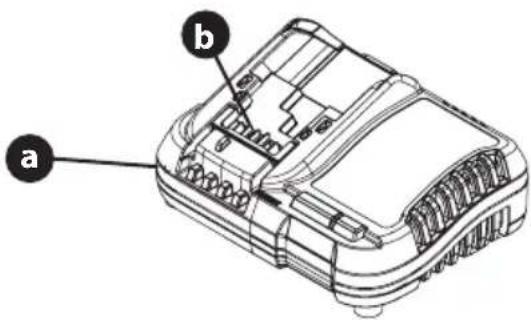
Figure 2
- Make sure the charger has not been shorted by debris. Inspect the terminals for soot and signs of melting. Do not attempt to use a damaged charger.
Transportation
WARNING
Fire hazard. Do not store or carry the battery pack so that metal objects can contact exposed battery terminals. For example, do not place the battery pack in aprons, pockets, tool boxes, product kit boxes, drawers, etc., with loose nails, screws, keys, etc. Transporting batteries can possibly cause fires if the battery terminals inadvertently come in contact with conductive materials such as keys, coins, hand tools and the like. The US Department of Transportation Hazardous Material Regulations (HMR) actually prohibit transporting batteries in commerce or on airplanes in carry-on baggage UNLESS they are properly protected from short circuits. When transporting individual battery packs, make sure that the battery terminals are protected and well-insulated from materials that could contact them and cause a short circuit.
NOTE: Li-ion batteries should not be put in checked baggage.
Overview
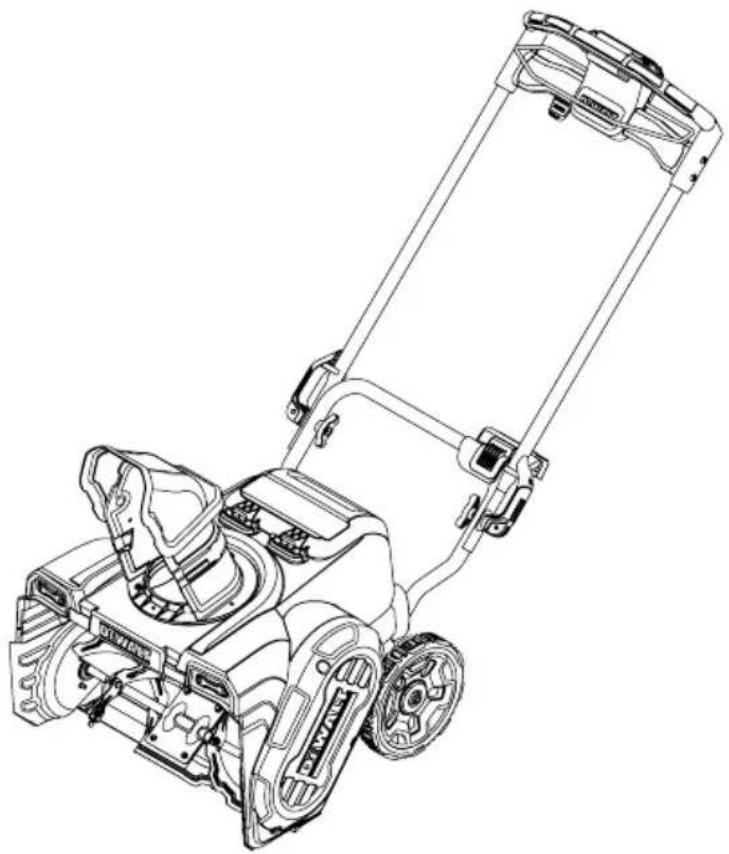
- Remove packaging materials from snow blower.
- Rotate Handle into the upright position and lock the handles in place. Refer to Handle Assembly.
• Install the chute. Refer to Chute Assembly Options. - Complete snow blower assembly. Refer to Set-Up on page 11.
Tools Required
- Adjustable Wrench or Socket Set
Assembly
- Charge batteries. Refer to Charging a Battery on page 8.
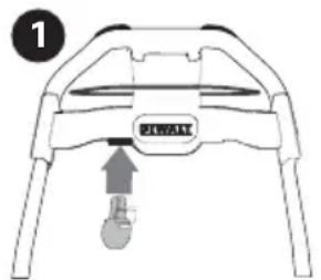
- Remove nut (a) and bolt from (b) lower handle (Figure 3).
- Using the nut and bolt removed in STEP 3, secure the handle sensor (c) to the lower handle.
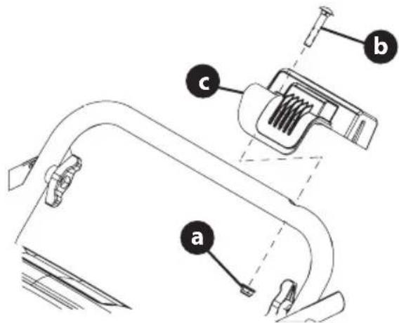
Figure 3
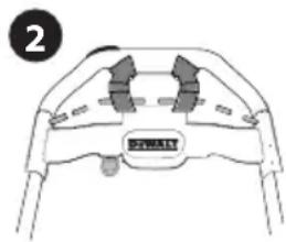
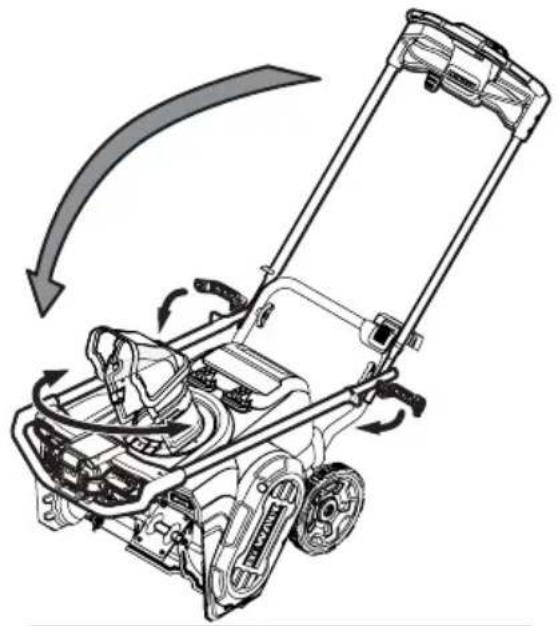
- Flip the two handle levers down to the Unlocked position (Figure 4).
NOTE: if the handle lever does not flip down, loosen the wing knob until the handle lever will flip down.
natural_image
Technical line drawing of a lawn mower with directional arrows indicating motion (no text or symbols)Figure 4
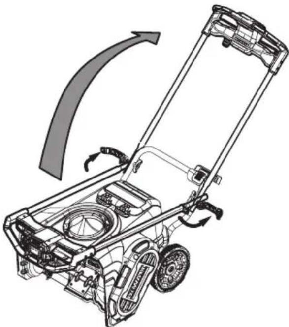
- Pivot the upper handle into the operating position. Be sure not to pinch any of the cables in the process (Figure 4).
- Flip the two handle levers (unlocked in STEP 4) up to the locked position to secure the upper handle in the operating position (Figure 5).
NOTE: Ensure the nub of the left handle lever engages the slot of the handle sensor.
natural_image
Mechanical assembly diagram showing a clamp mechanism with rotating arrows and a magnified inset (no text or symbols)Figure 5
NOTE: If necessary, adjust the wing knob so that the handle lever is tight enough to hold the upper handle in the operation position but loose enough for the handle lever to flip down to unlock the upper handle to be folded down to the storage position.
ASSEMBLY
Chute Assembly
- Remove the hex washer screws (a) in the chute base (Figure 6).
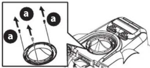
Figure 6
- Align the holes in the chute base with the three tabs (b) in the lower chute.
- Secure the chute base with the hex washer screws (a) removed in Step 2 (Figure 7).
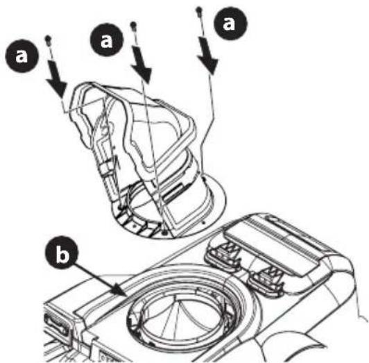
Figure 7
Set-Up
CHECKING THE BATTERY CHARGE LEVEL
Press the charge meter button on the battery (Figure 8). The number of lights that illuminate will indicate the current charge level of the battery. If all three lights are dark, charge the battery before any further use. Refer to Charging a Battery on page 8.
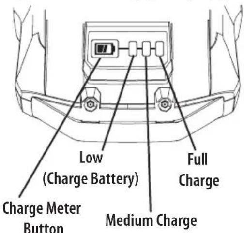
Figure 8
NOTE: While in use, lithium-ion batteries provide power with minimal power fade. When the battery is fully discharged, it will immediately cut power to the snow blower and require charging.
WARNING
Do not expose the snow blower to rain or wet conditions.
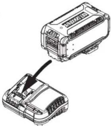
INSTALLING BATTERY
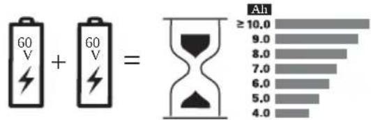
IMPORTANT: Only use DeWalt Flexvolt battery system batteries (DCB612 recommended) with this snow blower.
NOTE: The snow blower can operate with a single, fully charged battery but it is not recommended as it will result in less run time and reduced performance.
- Lift up the battery housing lid.
- Slide one battery (a) into the battery port (b) so that the battery indicator light faces up from the battery port (Figure 9).
- Push the battery firmly until the battery locks into place. There should be an audible "click" when the battery is in position.
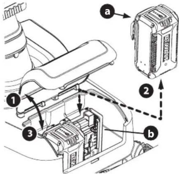
Figure 9
- Repeat STEPS 2 and 3 to install a second battery into the remaining battery port.
- Close battery housing lid and ensure the battery housing lid snaps into the shroud.
OPERATION
Model Features
Figure 10
FEATURES
Snow blower controls and features are described below and illustrated above (Figure 10).
NOTE: This Operator's Manual covers several models. Snow blower features may vary by model. Not all features in this manual are applicable to all snow blower models and the snow blower depicted may differ from yours.
NOTE: All references to the left or right side of the snow blower are from the operator's position. Any exceptions will be noted.
A. BATTERY (IF EQUIPPED)
The batteries are used to power the snow blower.
NOTE: Select models are sold as snow blower only. Batteries are available separately.
B. BATTERY CHARGER (IF EQUIPPED)
The battery charger is used to charge batteries.
NOTE: Select models are sold as snow blower only. Battery chargers are available separately.
C. SAFETY KEY
The safety key is a safety device. It must be fully inserted in order for the motor to start. Remove the safety key when the snow blower is not in use.
D. START BUTTON
Turns power on/off to the snow blower motor.
E. MODE BUTTON
The mode button is used to cycle through the Three operational modes of the snow blower:
- Eco Mode - Reduces auger speed and power to increase battery run time in light snow conditions.
- Standard Mode- Normal operating speed and power, used for most applications.
NOTE: The snow blower will start in standard mode.
- Max Power Mode - Increases auger speed and power. Used in heavy, wet snow conditions. This mode will reduce run time.
F. INDICATOR PANEL
The indicator panel provides the following information:
OPERATION
- Battery indicators - shows if a battery is installed in one or both of the battery slots and how much charge each battery has. When all indicator lights are lit the battery is at full charge. As the battery is discharging, the indicator lights will lower. When bottom battery indicator light begins to flash, the battery(ies) are nearing complete discharge.
NOTE: Battery Fault Indicator - Battery indicators will flash when a battery fault is detected. Stop motor and remove safety key and battery(ies). Reinstall battery(ies) and safety key. Start then stop the motor. If problem persists, contact an authorized service center.
-
Fault indicator - Indicates an error with the snow blower and will be shutting down.
-
Blinking Indicator - Snow blower is overheating from being over worked. Release auger control bail and allow snow blower to cool before continuing.
-
Steady Indicator - Error or Failure in Electronics, motor or battery and snow blower will shut down. Stop motor and remove safety key and battery(ies). Reinstall battery(ies) and safety key. Start then stop the motor. If problem persists, contact an authorized service center.
-
Heavy Load Indicator - Indicates the snow blower is in a high load condition that will result in a lower run time. Pause moving the snow blower forward. When the heavy load indicator light goes out, Slowly move forward to continue removing snow.
- Eco Mode indicator - Shows eco mode is active. Reduced auger speed to extend runtime.
NOTE: Snow blower will cycle into standard mode (no indicator lights will be lit) before going into max power mode.
- Max Power Mode indicator - Shows max power mode is active. - Increased auger speed to remove heavier snow. Reduces run time.
G. CHUTE DIRECTION CONTROLS
The left side (G1) and a right side (G2) chute direction controls are used to rotate the chute. Depress the right or left side chute direction controls to rotate the chute assembly to the left or right. Release the switch at desired position.
NOTE: Chute will also stop rotating when the chute has rotated through full range of motion.
H. AUGER CONTROL BAIL
The auger control bail is used to engage or disengage the auger. Squeeze the auger control bail against the upper handle and press the start button to engage the auger, release the bail to disengage.
I. HANDLE SENSOR
The handle sensor is located on the lower handle and detects if the handle is completely folded or locked into the upright position. The snow blower will not operate unless the handle is in the full upright position.
J. MANUAL CHUTE PITCH
Tilt the upper chute assembly up or down to adjusts the angle (pitch) and distance that snow is blown.
K. HEADLIGHTS
The headlights (front of snow blower) will remain ON when the snow blower is running.
L. AUGER
When engaged, the auger rotation draws snow into the auger housing and blows it out the chute assembly.
M. SHAVE PLATE
The shave plate maintains contact with the pavement as the snow blower is pushed, allowing snow close to the pavement's surface to be discharged.
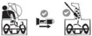
Using The Snow Blower
- Insert the safety key (a) into lower edge of the upper handle until it snaps in place (Figure 11).
- Pull the auger control bail against the upper handle.
- Press the start button (b).
NOTE: Press the start button within 3 seconds of pulling the auger control bail against the upper handle. If the snow blower does not start, release the auger control bail and repeat STEPS 2-3.
natural_image
Top-down schematic of a mechanical component with labeled parts (no text or symbols beyond label)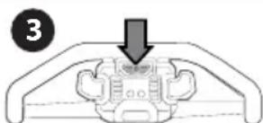
natural_image
Diagram of a mechanical component with a downward arrow indicating force or movement (no text or symbols present)Figure 11
ENGAGING THE AUGER
To engage the auger and start throwing snow, squeeze the auger control bail against the upper handle and press the start button. Release the auger control bail to stop the auger (Figure 11).
OPERATION
- Release the auger control bail to stop the motor and auger (Figure 11).
- Remove the safety key if snow blower is to be left unattended
NOTE: The snow blower will start in standard mode.
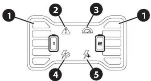
The mode button is used to cycle through the Three operational modes of the snow blower (Figure 12).
- Press the mode button (a) to change from the standard Mode to the max power mode. Max power mode indicator (b) lights up.
- Press the mode button again to change from max power mode to eco mode. Max power mode indicator goes out and the eco mode indicator (c) lights up.
- Press the mode button again to change from eco mode to standard mode. Both eco and max power mode indicators will go out.
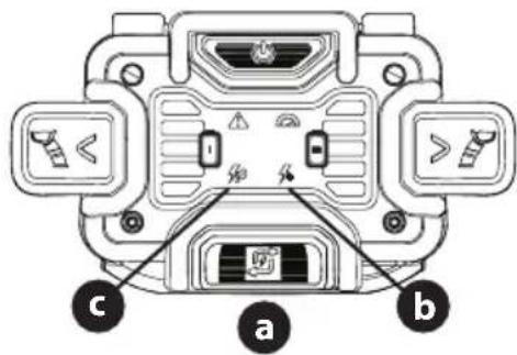
Figure 12
Adjusting the Chute Direction and Pitch
NOTE: The Chute must be rotated to the left or right before folding the handle.
CHUTE DIRECTION
- Rotating Chute to The Left - Press and hold the left side chute direction control (b) until the desired position has been achieved. Release the left side chute direction control.
- Rotating Chute to The Right - Press and hold the right side chute direction control (a) until the desired position has been achieved. Release the right side chute direction control.
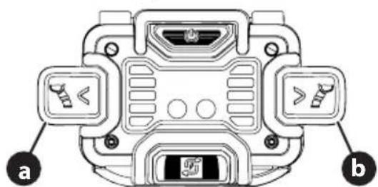
Figure 13
CHUTE PITCH
NOTE: Chute pitch controls the angle and distance of how far snow is blown.
- Loosen wing nut (a) (Figure 14).
-
Pivot the upper chute assembly upward or downward to desired position.
-
Tighten wing nut.
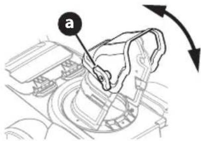
Figure 14
REMOVING THE BATTERY(IES)
IMPORTANT: Recommended use with two DCB612 batteries.
When one or both batteries need to be charged, follow the steps below to remove them:
- Lift up the battery housing lid.
- Push in the battery release tab (a).
- While pushing in the battery release tab, firmly pull the battery (b) out from the battery port (c).
NOTE: If necessary, repeat STEPS 2 and 3 to remove the remaining battery from the snow blower.
NOTE: To replace with charged battery, refer to Installing Battery on page 11.
4. Close battery housing lid.
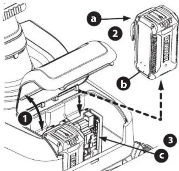
Figure 15
- Repeat STEPS 2 and 3 to remove the second battery.
- Close battery housing lid.
OPERATION
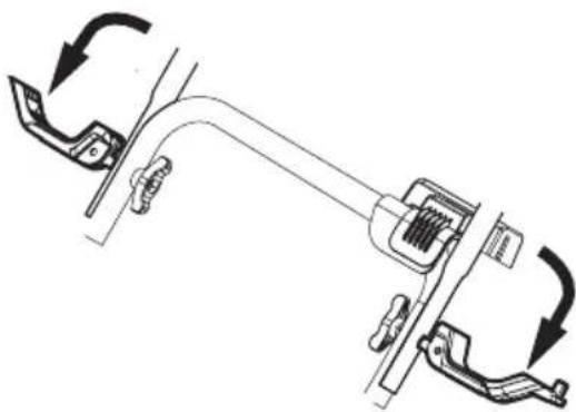
Folding and Unfolding the Handle
NOTE: When folding or unfolding the handle, If necessary, adjust the wing knobs so that the handle levers are tight enough to hold the upper handle in the operation position but loose enough for the handle lever to flip down to unlock the upper handle to be folded down to the storage position.
- Rotate the chute completely to the right or left. Refer to Adjusting the Chute Direction and Pitch on page 14.
- Flip the two handle levers down to the Unlocked position (Figure 16).
natural_image
Mechanical assembly diagram showing a clamp or bracket with directional arrows indicating motion (no text or symbols)Figure 16
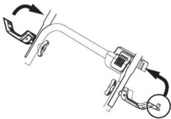
- Pivot the upper handle down to the folded position. Be sure not to pinch any of the cables in the process (Figure 17).
- Flip the two handle levers (unlocked in STEP 2) into the locked position.
- Reverse STEPS 1-4 to unfold the handle.
natural_image
Diagram of a lawn mower with directional arrows indicating motion (no text or symbols)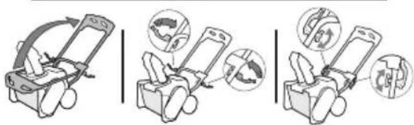
Figure 17
Clearing a Clogged Chute Assembly
WARNING
Never use your hands to clear a clogged chute assembly. Shut OFF motor and remain behind handles until all moving parts have stopped before using the clean-out tool to clear the chute assembly.
Hand contact with the rotating auger inside the chute assembly is the most common cause of injury associated with snow blowers. Never use your hand to clean out the chute assembly.
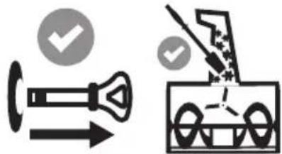
To clear the chute (Figure 18):
- TURN THE SNOW BLOWER OFF.
- Remove safety key.
- Wait 10 seconds to be sure the auger has stopped rotating.
IMPORTANT: Always use a clean-out tool (Part No. 931-2643), not your hands. Refer to the separate supplement for clean-out tool ordering information.
natural_image
Two technical diagrams showing a valve and a truck with checkmarks indicating approval or verification (no text or symbols present)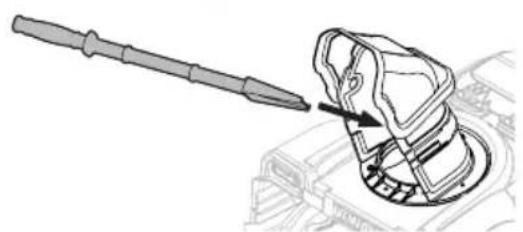
natural_image
Technical line drawing of a mechanical component with a tool inserted, showing a curved assembly (no text or symbols)Figure 18

WARNING
Before servicing, repairing or inspecting the snow blower, disengage the auger control bail. Stop the motor and remove safety key to prevent unintended starting.
Troubleshooting
BATTERY WILL NOT CHARGE
- The battery charger is not plugged in.
- Plug the battery charger into a 120V 60hz AC source.
- The battery is not fully inserted into the battery charger.
- Remove and then reinsert the battery into the battery charger.
- The battery and/or charger are too hot or too cold.
- Make sure the battery and charger are in an environment between 32^ and 104^ ( 0^ and 40^ ). Allow time for the battery and/or charger to warm up or cool down.
- The battery and/or charger are no longer functional.
- Refer to the Warranty Supplement for replacement information.
SNOW BLOWER FAILS TO START
- Safety key not inserted into starter housing.
- Insert safety key fully into starter housing.
- Auger control disengaged.
- Engage auger control bail.
- Starting procedure incomplete or performed out of order.
- Press auger control bail against the handle then press the start button to start motor.
- Battery discharged.
- Charge battery.
- The battery is not installed correctly.
- Remove safety key and battery(ies). Reinstall battery(ies) and safety key.
- Handle lock lever not fully engaged with handle sensor.
- Ensure handle lock lever is completely in the locked position and nub of handle lock lever is engaged with the handle sensor.
BATTERY DIES QUICKLY
- The battery is not fully charged.
- Charge the battery completely.
- The battery and/or charger are no longer functional.
- Refer to the Warranty Supplement for replacement information.
- Using unit outside temperature range.
- Battery(ies) too hot - Allow battery to cool.
- Battery(ies) too cold - Bring battery(ies) inside to warm up to room temperature.
SNOW BLOWER STOPS WHILE REMOVING SNOW
- Battery discharged or lacks sufficient charge.
- Charge battery completely.
- Chute assembly clogged.
- Stop motor and remove safety key. Clean chute and inside of the auger housing with clean-out tool.
- Battery is over heated.
- Allow battery to cool.
- Using unit outside temperature range.
- Battery(ies) too hot - Allow battery to cool.
- Battery(ies) too cold – Bring battery(ies) inside to warm up to room temperature.
EXCESSIVE VIBRATION
- Loose parts or damaged auger.
- Stop motor immediately and remove safety key and battery(ies). Check for possible damage. Tighten all nuts and bolts. Repair as needed. If the problem persists, contact an authorized service center.
AUGERS CONTINUE TO ROTATE
- Potential electrical issue.
- Stop motor and remove safety key and battery(ies). Reinstall battery(ies) and safety key. Start then stop the motor. If problem persists, contact an authorized service center.
FAILS TO DISCHARGE SNOW
- Chute assembly clogged.
- Stop motor and remove safety key. Clean chute and inside of the auger housing with clean-out tool.
- Foreign object lodged in auger.
- Stop motor immediately and remove safety key. Remove the object from auger.
- Auger drive belt loose or damaged.
- Replace auger drive belt. See Replacing the Auger Drive Belt in the Service section.
Maintenance
OFF-SEASON STORAGE
If the snow blower will not be used until next season, follow the storage instructions below.
-
Remove safety key and battery(ies).
-
Store in a clean, dry area.
PRODUCT CARE
- Use air or a dry rag to clean the outside of the snow blower, battery and battery charger.
IMPORTANT: DO NOT wash the snow blower with water. The warranty will be voided if water is used on the snow blower.
IMPORTANT: When storing the snow blower or when it is not being serviced, it is to remain in the upright position with both wheels and auger housing on the ground.
NOTE: Refer to Battery Charger Operator's Manual for information on storing your batteries.
- Fold Handle.
Service
REPLACING THE AUGER DRIVE BELT
- Ensure the snow blower is turned off and the safety key is removed.
- Remove battery(ies).
- Remove the four hex washer screws (a) that secure the belt cover (b) to the motor plate (Figure 19). Remove the belt cover.
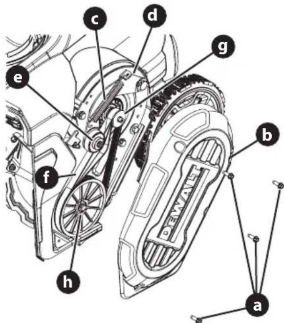
Figure 19
- Using a needle nose pliers or spring puller, release tension on idler pulley spring (c) and disconnect the idler pulley spring from the idler pulley bracket (d).
- Lift the idler pulley (e) and remove the belt (f).
- Route the new auger belt around the drive pulley (g) and under the idler pulley.
- Route the end of the belt around the auger pulley (h).
- Reconnect the idler pulley spring to the idler pulley bracket.
- Reinstall the belt cover removed in Step 3.
REPLACING SHAVE PLATE
NOTE: The shave plate is attached to the bottom of the auger housing and is subject to wear. It should be checked periodically.
- Ensure the snow blower is turned off and the safety key is removed.
- Remove battery(ies).
- Tip the snow blower back until it rests on the handles.
- Remove the four star screws (a) securing the shave plate (b) to the auger housing (c) (Figure 20).
NOTE: the two center star screws also secures the bottom shroud to the auger housing.
- Remove the existing shave plate.
- Install the new shave plate.
- Using the star four screws removed in STEP 4, secure the new shave plate and bottom support plate to the auger housing.
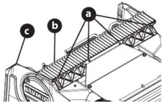
Figure 20
Battery Disposal
THE RBRC® SEAL
The RBRC® (Rechargeable Battery Recycling Corporation) Seal on the nickel cadmium, nickel metal hydride or lithium-ion batteries (or battery packs) indicates that the costs to recycle these batteries (or battery packs) at the end

of their useful life have already been paid by the manufacturer. In some areas, it is illegal to place spent nickel cadmium, nickel metal hydride or lithium-ion batteries in the trash or municipal solid waste stream and the Call 2 Recycle® program provides an environmentally conscious alternative.
Call 2 Recycle, Inc., in cooperation with the manufacturer and other battery users, has established the program in the United States and Canada to facilitate the collection of spent nickel cadmium, nickel metal hydride or lithium-ion batteries. Help protect our environment and conserve natural resources by returning the spent nickel cadmium, nickel metal hydride or lithium-ion batteries to an authorized service center or to your local retailer for recycling. You may also contact your local recycling center for information on where to drop off the spent battery. RBRC® is a registered trademark of Call 2 Recycle, Inc.
PRODUCT CARE
Three Year Limited Warranty
DeWALT will repair or replace, without charge, any defects due to faulty materials or workmanship for three years from the date of purchase. This warranty does not cover part failure due to normal wear or tool abuse. For further detail of warranty coverage and warranty repair information, visit www.dewalt.com or call 1-800-4-DeWALT (1-800-433-9258). This warranty does not apply to accessories or damage caused where repairs have been made or attempted by others. THIS LIMITED WARRANTY IS GIVEN IN LIEU OF ALL OTHERS, INCLUDING
THE IMPLIED WARRANTY OF MERCHANTABILITY AND FITNESS FOR A PARTICULAR PURPOSE, AND EXCLUDES ALL INCIDENTAL OR CONSEQUENTIAL DAMAGES. Some states do not allow limitations on how long an implied warranty lasts or the exclusion or limitation of incidental or consequential damages, so these limitations may not apply to you. This warranty gives you specific legal rights and you may have other rights which vary in certain states or provinces. In addition to the warranty DeWALT tools are covered by our:
1 YEAR FREE SERVICE
DeWALT will maintain the tool and replace worn parts caused by normal use, for free, any time during the first two years after purchase.
2 YEARS FREE SERVICE ON DEWALT BATTERY PACKS
DC9071, DC9091, DC9096, DC9182, DC9280, DC9360, DCB120, DCB122, DCB124, DCB127, DCB201, DCB203BT, DCB207, DCB361
3 YEARS FREE SERVICE ON DEWALT BATTERY PACKS
DCB200, DCB203, DCB204, DCB204BT, DCB205, DCB205BT, DCB206, DCB208, DCB230, DCB240, DCB606, DCB609, DCB612
NOTE: Battery warranty voided if the battery pack is tampered with in any way. DeWALT is not responsible for any injury caused by tampering and may prosecute warranty fraud to the fullest extent permitted by law.
90 DAY MONEY BACK GUARANTEE
If you are not completely satisfied with the performance of your DeWALT Power Tool or Nailer for any reason, you can return it within 90 days from the date of purchase with a receipt for a full refund – no questions asked.
LATIN AMERICA: This warranty does not apply to products sold in Latin America. For products sold in Latin America, see country specific warranty information contained in the packaging, call the local company or see website for warranty information.
FREE WARNING LABEL REPLACEMENT: If your warning labels become illegible or are missing, call 1-800-4-DeWALT (1-800-433-9258) for a free replacement.
Replacement Parts
| Part Number Description | |
| BD-NA262050 Safety key | |
| 754P07144 Auger belt | |
| BD-NA171659 Wheels | |
| BD-NA110007 Battery Model DCB612 | |
| BD-N878449 Battery charger Model DCB1104 |
Accesories
| Part Number Description | |
| 931-2643 Chute Clean-out Tool |
natural_image
Line drawing of a lawn mower with attached motors and wheels (no text or symbols)
natural_image
Technical illustration of a device housing with an arrow pointing to a component (no text or symbols present)Figura 1
Figura 3
natural_image
Line drawing of a lawn mower with a curved arrow indicating motion (no text or symbols)Figura 4
natural_image
Mechanical assembly diagram showing a linkage mechanism with no text or symbolsFigura 5
Figura 6
Figura 9
Figura 10
CARACTERÍSTICAS
A. BATERÍA (SI SE INCLUYE)
natural_image
Mechanical assembly diagram showing a clamp or bracket with directional arrows indicating motion (no text or symbols present)Figura 16
Figura 17
Figura 18

ADVERTENCIA
Figura 19
DC9071, DC9091, DC9096, DC9182, DC9280, DC9360, DCB120, DCB122, DCB124, DCB127, DCB201, DCB203BT, DCB207, DCB361
DCB200, DCB203, DCB204, DCB204BT, DCB205, DCB205BT, DCB206, DCB208, DCB230, DCB240, DCB606, DCB609, DCB612
natural_image
Line drawing of a lawn mower with attached motors and wheels (no text or symbols)
natural_image
Technical line drawing of a mechanical component with an arrow pointing to a section (no text or symbols present)Figure 1
Figure 3
natural_image
Line drawing of a lawn mower with a curved arrow indicating motion (no text or symbols)Figure 4
natural_image
Mechanical assembly diagram showing a linkage mechanism with arrows indicating motion (no text or symbols)Figure 5
Figure 6
Figure 9
Figure 10
CARACTÉRISTIQUES
natural_image
Top-down line drawing of a mechanical component with no visible text or symbols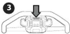
natural_image
Diagram of a mechanical component with a downward arrow indicating force or movement (no text or symbols present)Figure 11
EMBRAYAGE DE LA TARIÈRE
Figure 12
Figure 15
natural_image
Mechanical assembly diagram showing a clamp or bracket with directional arrows indicating motion (no text or symbols)Figure 16
Figure 17
Figure 18

AVERTISSEMENT
Figure 19
DC9071, DC9091, DC9096, DC9182, DC9280, DC9360, DCB120, DCB122, DCB124, DCB127, DCB201, DCB203BT, DCB207, DCB361
3 ANS DE SERVICE GRATUIT SUR LES BLOCS-BATTERIES DEWALT
DCB200, DCB203, DCB204, DCB204BT, DCB205, DCB205BT, DCB206, DCB208, DCB230, DCB240, DCB606, DCB609, DCB612