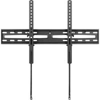
BE-TVLTLC - Wall mount Best Buy - Free user manual and instructions
Find the device manual for free BE-TVLTLC Best Buy in PDF.


| Product Type | Tilting Wall Mount for TV |
| Brand | Best Buy |
| Model | BE-TVLTLC / BE-TVLTLC-C |
| Screen Compatibility | Flat-screen TVs from 47 to 84 inches (119.4 to 213.4 cm) |
| VESA Standard | 100x100 to 600x400 mm (includes all common intermediate sizes) |
| Maximum Load Capacity | 49.89 kg (110 lb) |
| Tilt Range | -15° to +3° |
| Material | Durable Steel |
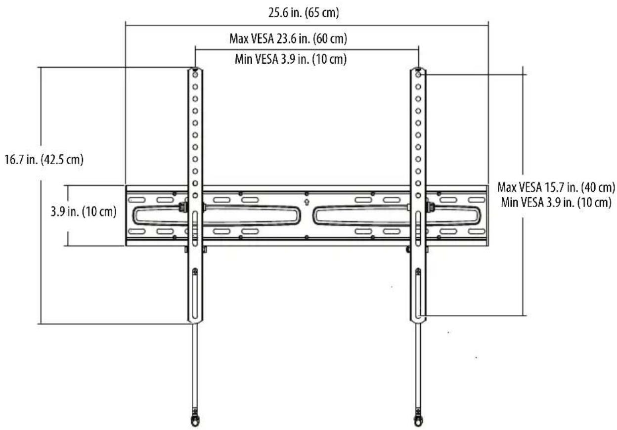
| Wall Plate Dimensions (W × H) | 65 cm × 42.5 cm (25.6 × 16.7 in) |
| Depth | Varies with tilt and TV thickness |
| Package Contents | Wall plate (A), left and right brackets (B and C), template (D), lag bolts (E), concrete anchors (F), level (G), assorted screws and spacers, washers |
| Wall Mount Type | On wood studs or concrete/concrete block wall |
| Required Tools | Drill, 7/32 in (5.5 mm) wood drill bit or 10 mm concrete drill bit, 1/2 in socket wrench, level, stud finder, tape measure, pencil, Phillips screwdriver |
| Warranty | 1 year (365 days) from date of purchase |
| Customer Service | Phone: 1-866-597-8427 (United States and Canada) |
| Care and Cleaning | Wipe with a soft dry cloth. Do not use abrasive products. |
| Safety | Do not exceed maximum load. Installation by two qualified persons. Do not allow children to climb or play on the mount. Check wall solidity. |
| Replacement Parts and Repairability | Contact customer service for free replacement parts if needed. |
| General Information | Distributed by Best Buy Purchasing, LLC, 7601 Penn Av. South, Richfield, MN 55423, USA. ©2024 Best Buy. All rights reserved. |
Frequently Asked Questions - BE-TVLTLC Best Buy
User questions about BE-TVLTLC Best Buy
0 question about this device. Answer the ones you know or ask your own.
Ask a new question about this device
Download the instructions for your Wall mount in PDF format for free! Find your manual BE-TVLTLC - Best Buy and take your electronic device back in hand. On this page are published all the documents necessary for the use of your device. BE-TVLTLC by Best Buy.
USER MANUAL BE-TVLTLC Best Buy
BEST BUY essentials™
BEST BUY essentials™
Contents/Table des matières/Contenido ENGLISH....4
SAFETY INFORMATION INSTRUCTIONS 4
Features....4 VESA TV screw hole patterns....5 Dimensions....5
Tools needed 6
Package contents....6 Parts....6 TV Mounting Hardware....7
Installation instructions....8 STEP 1- Determine whether your TV has a flat, irregular, or obstructed back...8 STEP 2 - Select screws, washers, and spacers....9 STEP 3 - Option 1: Attach hardware to a flat back TV....10 STEP 3 - Option 2: Attach hardware to an irregular or obstructed back TV....12 STEP 4 - Determine wall-mount location....14 STEP 5 - Option 1: Install on a wood stud wall....15 STEP 5 - Option 2: Install on a solid concrete or concrete block wall....18 STEP 6 - Mount your TV to the wall plate....21 STEP 7 - Adjust the tilt angle....22
ONE-YEAR LIMITED WARRANTY ....23
FRANÇAIS....25
INFORMATIONS SUR LA SÉCURITÉ ....25
GARANTIE LIMITÉE D'UN AN ....44
ESPAÑOL 46
INSTRUCCIONES DE SEGURIDAD IMPORTANTES.....46
Características....47
SAFETY INFORMATION INSTRUCTIONS
CAUTION:
Read this instruction carefully before assembly.
• Fits 47-84 in. flat panel TVs.
• Weight Capacity: 110 lbs. (49.89 kg)
SAFETY WARNINGS:
This mount is intended for use with TV weights not exceeding the maximum weight capacity of 110 lbs. (49.89 kg) The wall itself must be capable of supporting four times the standard weight. Do not over tighten screws in order to avoid any injury. Use with products heavier than the maximum weights indicated may result in collapse of the mount and its accessories, causing possible injury.
- Never let children climb on product or play with product.
- Do not sit or stand on product.
- Do not fasten a TV that is heavier than the recommended load rating to the mount.
- Use suitable concrete wall or wood stud wall.
- Use this mounting system only for its intended use as described in these instructions.
- Do not use attachments not recommended by the manufacturer.
- Do not use outdoors.
- Improper installation may cause property damage and/or personal injury, so the installation must be done by two qualified contractors. The manufacture is not liable for damage or injury caused by incorrect mounting, assembly, or use.
- Improper handling can result in cuts and lacerations.
• Pictures for reference only, subject to our available products. - Keep this instruction for future reference.
SAVE THESE INSTRUCTIONS
Features
• Supports TVs from 47–84" and up to 110 lbs. (49.89 kg)
- Compatible with VESA patterns from 100 × 100 to 600 × 400 (with all common sizes in between)
- Tilts -15° to 3° to adjust viewing angle
- Enjoy years of dependable use with our sturdy steel construction
- Backed by Best Buy
VESA TV screw hole patterns
Your wall mount works with the following VESA TV screw hole patterns:
| 100 × 100 mm (3.9 × 3.9") 400 × 3 | 00 mm (15.7 × 11.8") |
| 200 × 200 mm (7.9 × 7.9") 400 × 4 | 00 mm (15.7 × 15.7") |
| 300 × 200 mm (11.8 × 7.9") 500 × | 400 mm (19.7 × 15.7") |
| 300 × 300 mm (11.8 × 11.8") 600 × | 400 mm (23.6 × 15.7") |
| 400 × 200 mm (15.7 × 7.9") |
Dimensions
Tools needed
You will need the following tools to assemble your new TV wall mount:
Edge-to-edge stud finder

Pencil
7/32 in. (5.5 mm) wood drill bit (for wood stud wall)
OR
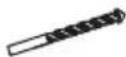
3/8 in. (10 mm) masonry drill bit (for concrete wall)

Masking tape
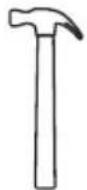
Hammer
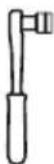
1/2" socket wrench
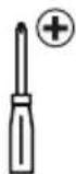
Phillips screwdriver Measuring tapeDrill
Package contents
Make sure that you have all the parts and hardware necessary to assemble your new TV wall mount.
Parts
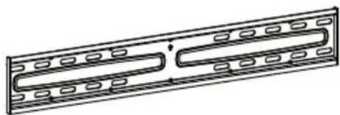
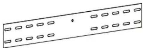
A Wall plate
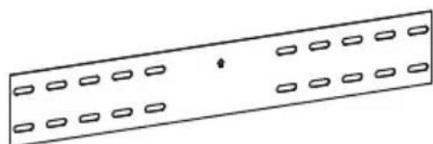
D Template

B Left TV bracket

C Right TV bracket
TV Mounting Hardware
| Label | Hardware Qty. | |
| E | 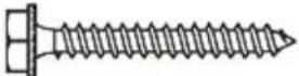 Lag screw M8 x 60mm Lag screw M8 x 60mm | 4 |
| F | 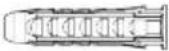 Concrete anchor Concrete anchor | 4 |
| G | 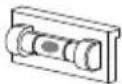 Level Level | 1 |
| H |  M4 × 12 mm screw M4 × 12 mm screw | 4 |
| I |  M6 × 12 mm screw M6 × 12 mm screw | 4 |
| J | 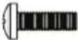 M6 × 20 mm screw M6 × 20 mm screw | 4 |
| K | 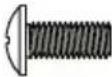 M8 × 20 mm screw M8 × 20 mm screw | 4 |
| L | 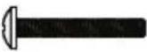 M4 × 35 mm screw M4 × 35 mm screw | 4 |
| M | 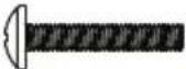 M6 × 35 mm screw M6 × 35 mm screw | 4 |
| Label | Hardware Qty. | ||
| N | 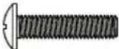 | M8 × 35 mm screw | 4 |
| O |  | M8 × 50 mm screw | 4 |
| P |  | M6 x 17 mm spacer | 4 |
| Q |  | M8 x 22 mm spacer | 4 |
| R |  | M8 x 10 mm spacer | 4 |
| S |  | M8 x 2.5 mm spacer | 8 |
| T |  | M4 washer | 4 |
| U |  | M6 washer | 4 |
Installation instructions
STEP 1- Determine whether your TV has a flat, irregular, or obstructed back
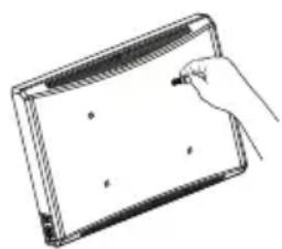
1 Carefully place your TV screen face-down on a cushioned, clean surface to protect the screen from damages and scratches.
2 If your TV has a table-top stand attached, remove the stand. See the documentation that came with your TV for instructions.
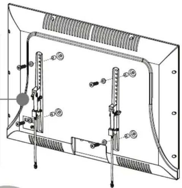
3 Lay the TV brackets, oriented vertically, on the back of your TV.
4 Align the screw holes in the TV brackets with the mounting screw holes on your TV.
5 Identify which type of back your TV has:
- Flat back: The brackets lay flush against the back of your TV and do not block any jacks. You do not need spacers when assembling the wall mount.
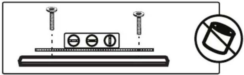
- Obstructed back: The brackets block one or more of the jacks on the back of your TV. You need spacers when assembling the wall mount.
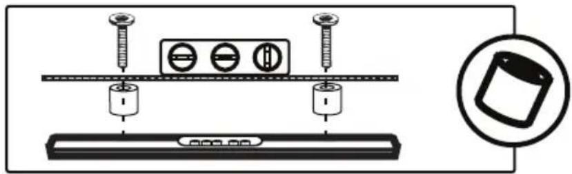
- Irregularly-shaped back: There is a gap between a bracket and some part of the back of your TV. You need spacers when assembling the wall mount.
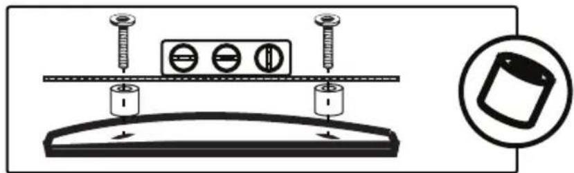
6 Remove the TV brackets.
STEP 2 - Select screws, washers, and spacers
1 Select the hardware for your TV (screws, washers, and spacers). A limited number of TVs come with mounting hardware included. (If there are screws that came with your TV, they are almost always in the holes on the back of your TV.) If you don't know the correct length of the mounting screws your TV requires, test various sizes by hand-threading the screws.
Select one of the following types of screws:
For a TV with a flat back:
M4 X 12 mm screws (H)
M6 X 12 mm screws (I)
M6 X 20 mm screws (J)
M8 X 20 mm screws (K)
For a TV with an irregular/obstructed back:
M4 X 35 mm screws (L)
M6 X 35 mm screws (M)
M8 X 35 mm screws (N)
M8 X 50 mm screws (O)
Select either an M4 washer (T) or an M6 washer (U) for the corresponding types of screws. For an irregular or obstructed TV back, also use the spacers (P, Q, R, or S).
Note: If the included hardware does not work for your TV, call 1-877-467-4289, for Insignia Customer Support, and we'll work to determine the necessary parts required and ship them to you without charge.
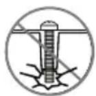
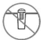
CAUTION: To avoid potential personal injuries and property damage, make sure that there are adequate threads to secure the brackets to your TV. If you encounter resistance, stop immediately and contact customer service. Use the shortest screw and spacer combination to accommodate your TV. Using hardware that is too long may damage your TV. However, using a screw that is too short may cause your TV to fall from the mount.
Screw fits correctly
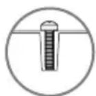
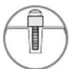
Screw is too long
Screw is too short
2 Remove the screws from the holes in the back of your TV.
3 For a flat back TV, go to STEP 3 - Option 1: Attach hardware to a flat back TV on page 10.
-OR-
For an irregular or obstructed back, go to STEP 3 - Option 2: Attach hardware to an irregular or obstructed back TV on page 12.
STEP 3 - Option 1: Attach hardware to a flat back TV You'll need
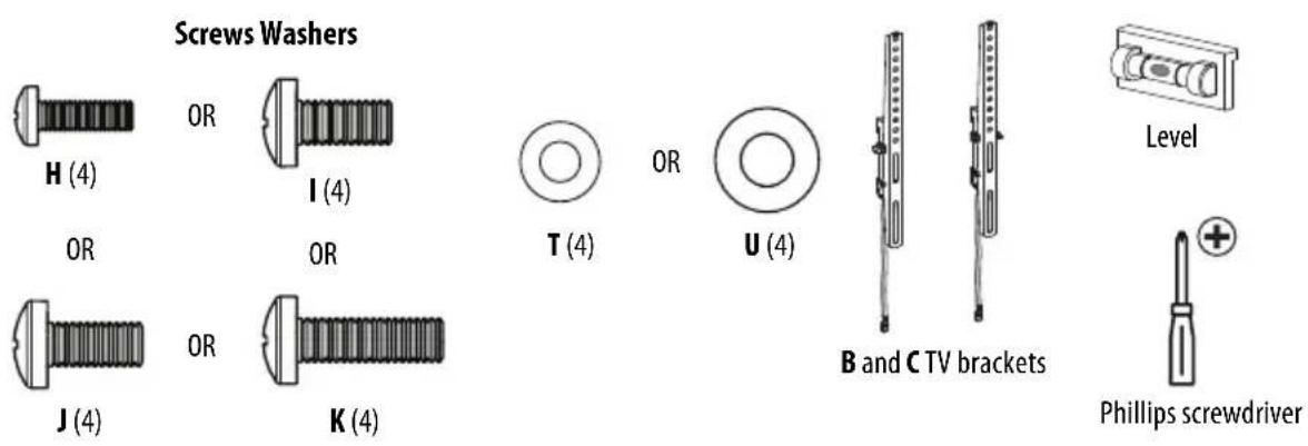
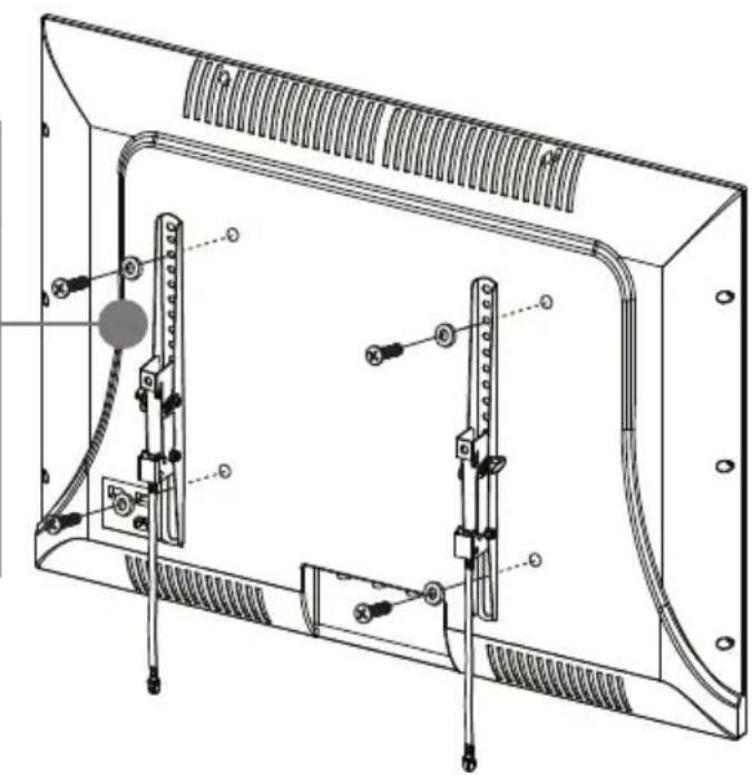
1 Align the left and right TV brackets (B and C) with the screw holes on the back of your TV. Make sure that the brackets are level.
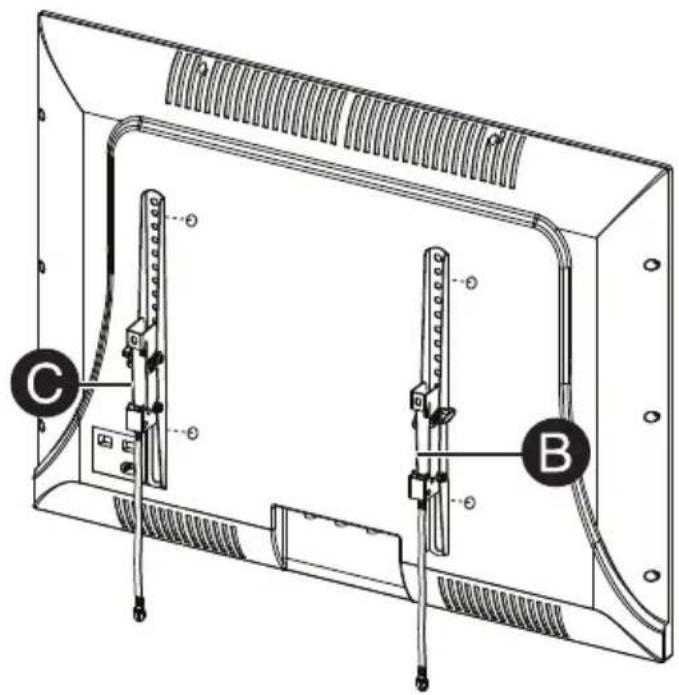
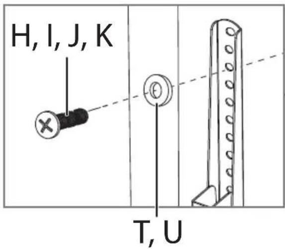
2 Install washers (T or U), and screws (H, I, J, or K) into the holes in the back of your TV. No washer is required if you use M8 screws (K).
3 Tighten the screws until they are snug against the TV brackets. Do not over tighten.
Note: No washer is required if you use M8 screws (K).

CAUTION: Do Not Use an electric drill
STEP 3 - Option 2: Attach hardware to an irregular or obstructed back TV
You'll need
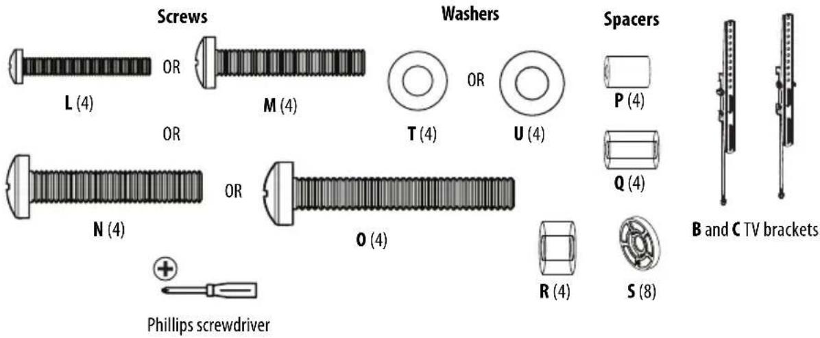
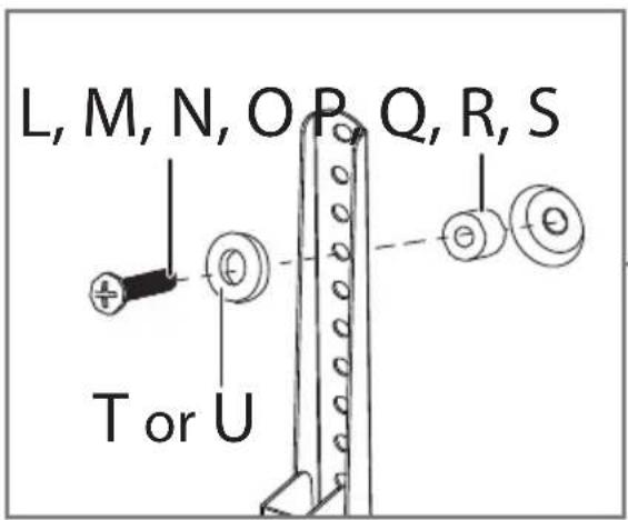
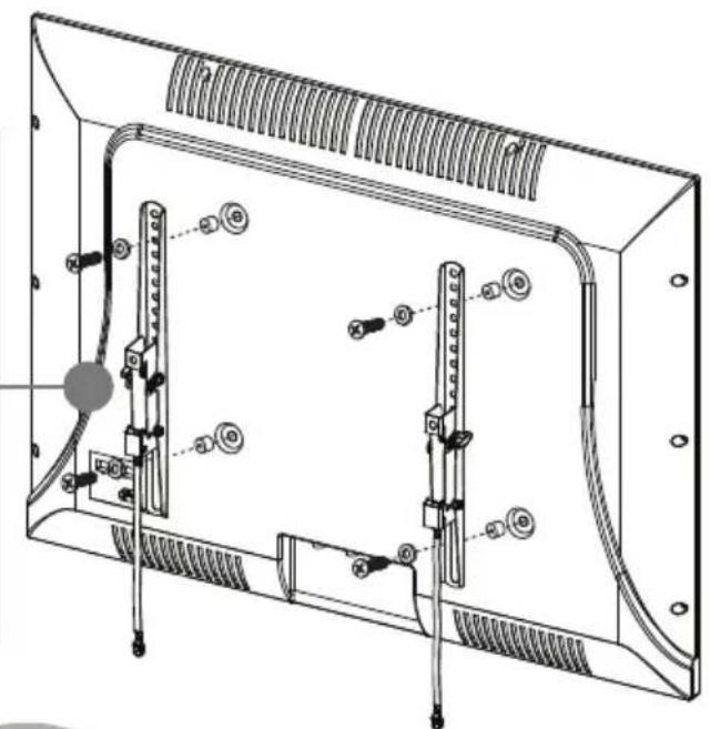
1 Place spacers (P, Q, R, or S) over the screw holes on the back of your TV.
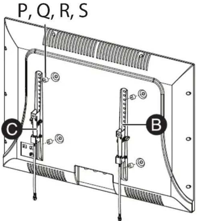
2 Align the left and right TV brackets (B and C) with the screw holes on the back of your TV. Make sure that the brackets are level.
3 If you are using M4 washers (T), place them between the spacers and TV brackets and over the holes in the TV brackets. If you are using M6 washers (U), place them over the holes in the TV brackets. Insert screws (L, M, N, or O) through the washers, TV brackets, and spacers. No washers are required if you use M8 screws (N or O).
4 Tighten the screws until they are snug against the TV brackets. Do not over tighten.
If you are using M4 (T) or M6 (U) washers (only), place them behind the brackets.
No washers are required If you use M8 screws (N or 0).

CAUTION: Do Not Use an electric drill
STEP 4 - Determine wall-mount location You'll need
Note: Your TV should be high enough so your eyes are level with the middle of the screen. This is normally 40 to 60 in. (106 to 152 cm) from the ground.
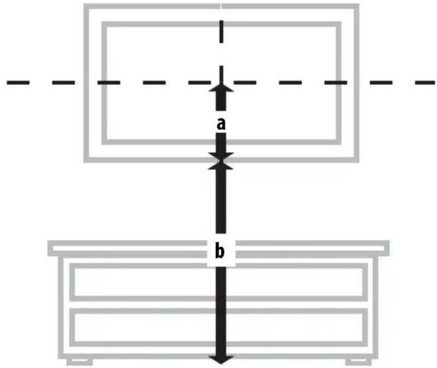
The center of your TV will be offset .8 in. (2 cm) lower than the center of the wall plate on the wall-mount. Before you drill holes in the wall:
1 Measure the distance from the bottom of your TV to the center point halfway between the top and bottom mounting holes on the back of your TV. This is measurement a.
2 Measure the distance from the floor to where you want the bottom of your TV to be placed on the wall. Keep in mind that the bottom of your TV should be placed above any furniture (such as entertainment centers or TV stands). Your TV should also be above items placed on top of the furniture (like a Blu-ray player or cable box). This measurement is b.
3 Add a + b. The total measurement is the height where you want the center of the wall plate to be on the wall.
4 Use a pencil to mark this spot on the wall.
STEP 5 - Option 1: Install on a wood stud wall
You'll need
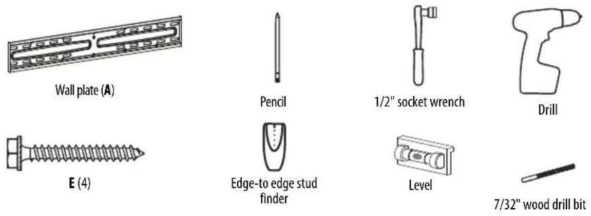
Note: Any drywall covering the wall must not exceed 5/8 in. (16 mm).
1 Locate the studs. Verify the centers of the studs with an edge-to-edge stud finder.

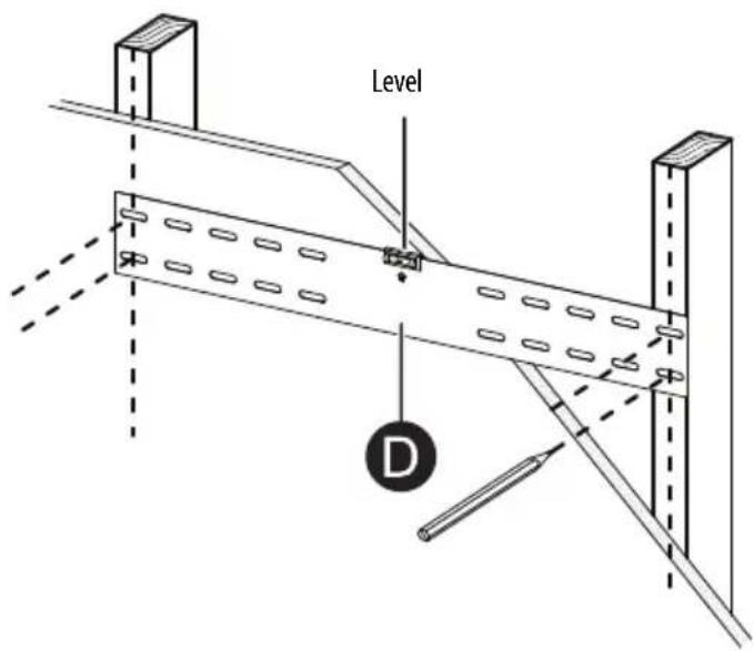
2 Align the template (D) at the height you determined in the previous step, make sure that it is level, then use a pencil to mark the lag screw hole locations (4) on the stud centers. Remove the template (D).
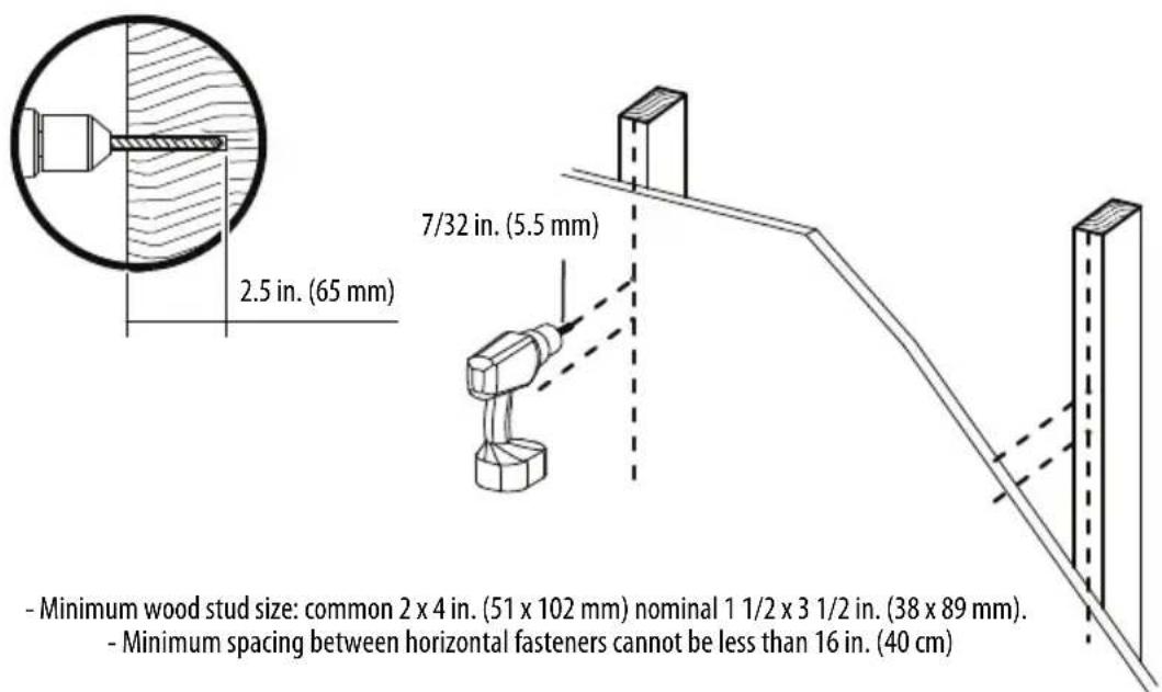
3 Drill pilot holes to a depth of 2.5 in. (65 mm) using a 7/32 in. (5.5 mm) diameter drill bit.
4 Align the wall plate (A) with the pilot holes, then insert the lag screws (E) through the holes in the wall plate. Tighten the lag screws only until they are firm against the wall plate.
Level
1/2" socket wrench
CAUTION: Avoid potential injuries or property damage! DO NOT over-tighten the lag screws (E).
STEP 5 - Option 2: Install on a solid concrete or concrete block wall
You'll need
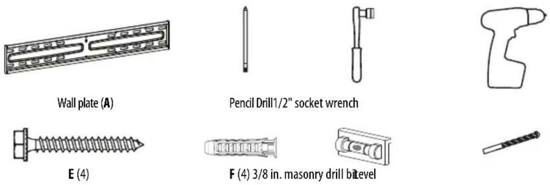
CAUTION: To prevent property damage or personal injury, never drill into mortar between blocks. Mount the wall plate directly onto the concrete surface.
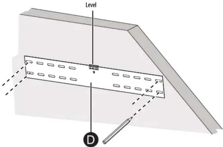
1 Align the template (D) at the height you determined in the previous step, make sure that it is level, then use a pencil to mark the lag screw hole locations (4). Remove the template (D).
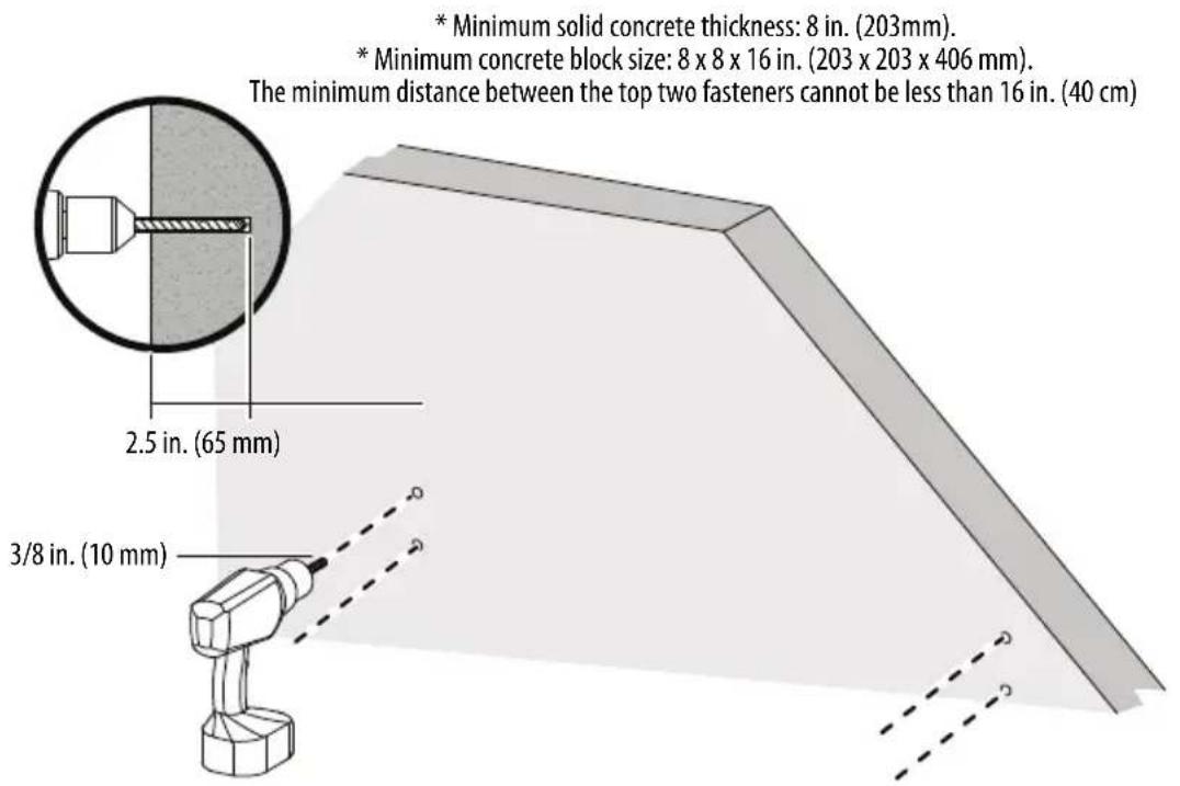
2 Drill pilot holes to a depth of 2.5 in. (65 mm) using a 3/8 in. (10 mm) diameter masonry drill bit.
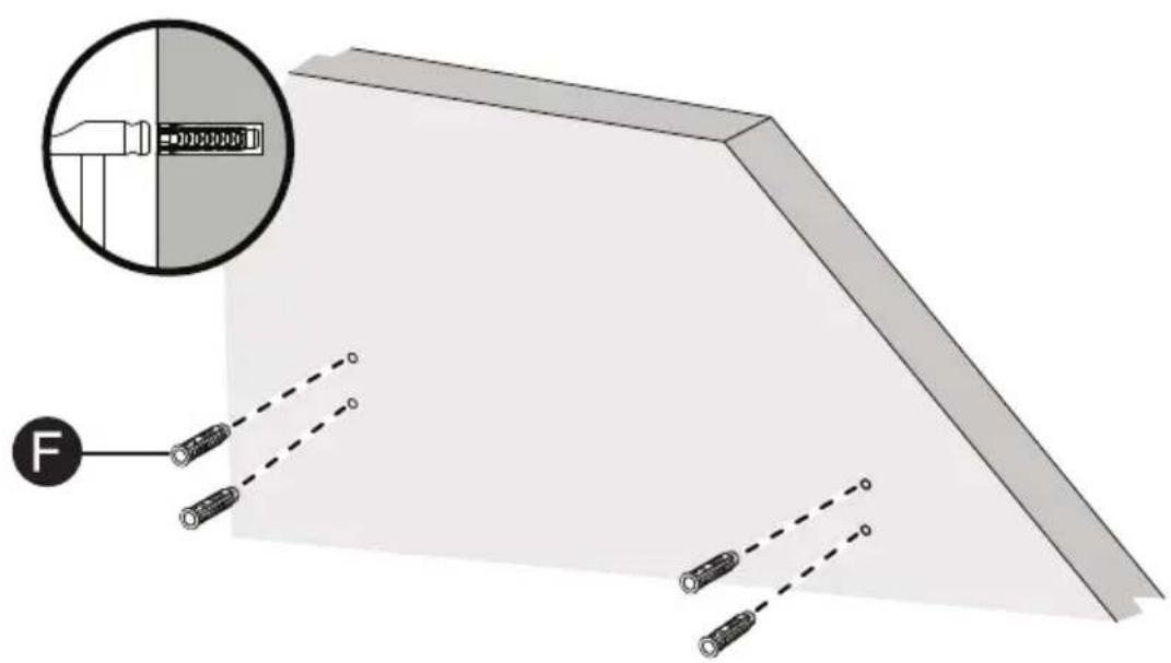
3 Insert the concrete wall anchors (F) into the pilot holes and use a hammer to make sure the anchors are flush with the concrete surface.
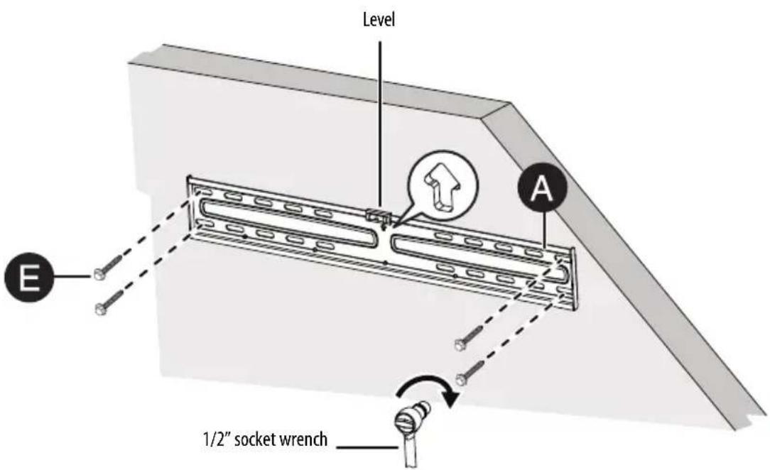
4 Align the wall plate (A) with the anchors, insert the lag screws (E) through the holes in the wall plate. Tighten the lag screws only until they are firm against the wall plate.
CAUTION: Avoid potential injuries or property damage! DO NOT over-tighten the lag screws (E).
STEP 6 - Mount your TV to the wall plate
WARNING: Heavy - you will need assistance with this step.
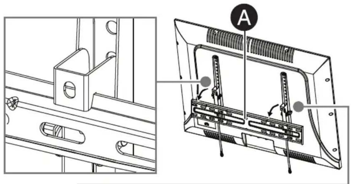
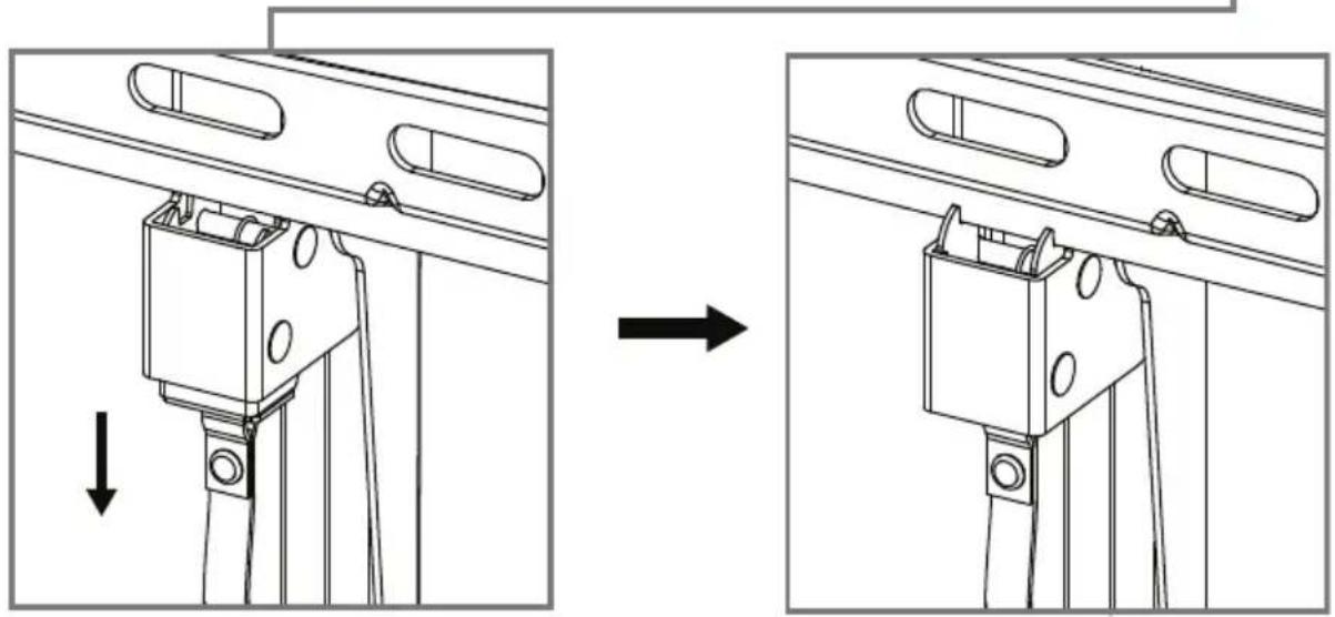
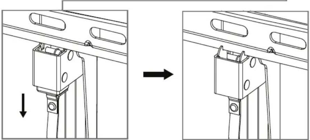
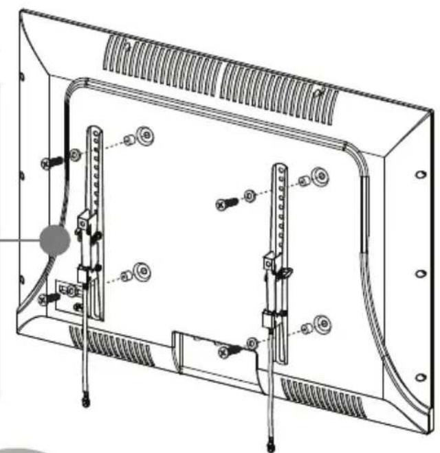
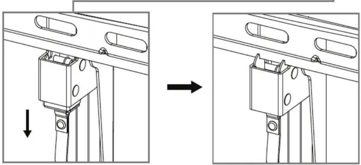
- Hang the pre-assembled TV unit onto the wall plate (A). Pull-down straps, then push the bottom of the TV/bracket assembly in toward the bottom of the wall place. Release the pull-down straps to lock the brackets in place.

CAUTION HEAVY! You will need assistance with this step.
STEP 7 - Adjust the tilt angle
- Adjust the TV tilt angle by loosening the handles of the TV brackets, when the angle is correct, tighten the handles.
Handle
+3°
Handle
-15°
ONE-YEAR LIMITED WARRANTY
Definitions:
The Distributor* of Best Buy Essentials branded products warrants to you, the original purchaser of this new Best Buy Essentials-branded product ("Product"), that the Product shall be free of defects in the original manufacturer of the material or workmanship for a period of one (1) year from the date of your purchase of the Product ("Warranty Period").
For this warranty to apply, your Product must be purchased in the United States or Canada from a Best Buy branded retail store or online at www.bestbuy.com or www.bestbuy.ca and is packaged with this warranty statement.
How long does the coverage last?
The Warranty Period lasts for 1 year (365 days) from the date you purchased the Product. Your purchase date is printed on the receipt you received with the Product.
What does this warranty cover?
During the Warranty Period, if the original manufacture of the material or workmanship of the Product is determined to be defective by an authorized Best Buy Essentials repair center or store personnel, Best Buy Essentials will (at its sole option): (1) repair the Product with new or rebuilt parts; or (2) replace the Product at no charge with new or rebuilt comparable products or parts. Products and parts replaced under this warranty become the property of Best Buy Essentials and are not returned to you. If service of Products or parts are required after the Warranty Period expires, you must pay all labor and parts charges. This warranty lasts as long as you own your Best Buy Essentials Product during the Warranty Period. Warranty coverage terminates if you sell or otherwise transfer the Product.
How to obtain warranty service?
If you purchased the Product at a Best Buy retail store location or from a Best Buy online website (www.bestbuy.com or www.bestbuy.ca), please take your original receipt and the Product to any Best Buy store. Make sure that you place the Product in its original packaging or packaging that provides the same amount of protection as the original packaging.
To obtain warranty service, in the United States and Canada call 1-866-597-8427. Call agents may diagnose and correct the issue over the phone.
Where is the warranty valid?
This warranty is valid only in the United States and Canada at Best Buy branded retail stores or websites to the original purchaser of the product in the country where the original purchase was made.
What does the warranty not cover?
This warranty does not cover:
Customer instruction/education
- Installation
- Setup adjustments
- Cosmetic damage
• Damage due to weather, lightning, and other acts of God, such as power surges
- Accidental damage
- Misuse
- Abuse
• Negligence
- Commercial purposes/use, including but not limited to use in a place of business or in communal areas of a multiple dwelling condominium or apartment complex, or otherwise used in a place of other than a private home.
- Modification of any part of the Product, including the antenna
- Display panel damaged by static (non-moving) images applied for lengthy periods (burn-in).
- Damage due to incorrect operation or maintenance
- Connection to an incorrect voltage or power supply
- Attempted repair by any person not authorized by BEST BUY ESSENTIALS to service the Product
- Products sold "as is" or "with all faults"
- Consumables, including but not limited to batteries (i.e. AA, AAA, C etc.)
- Products where the factory applied serial number has been altered or removed
- Loss or Theft of this product or any part of the product
- Display panels containing up to three (3) pixel failures (dots that are dark or incorrectly illuminated) grouped in an area smaller than one tenth (1/10) of the display size or up to five (5) pixel failures throughout the display. (Pixel based displays may contain a limited number of pixels that may not function normally.)
- Failures or Damage caused by any contact including but not limited to liquids, gels or pastes.
REPAIR REPLACEMENT AS PROVIDED UNDER THIS WARRANTY IS YOUR EXCLUSIVE REMEDY FOR BREACH OF WARRANTY. BEST BUY ESSENTIALS SHALL NOT BE LIABLE FOR ANY INCIDENTAL OR CONSEQUENTIAL DAMAGES FOR THE BREACH OF ANY EXPRESS OR IMPLIED WARRANTY ON THIS PRODUCT, INCLUDING, BUT NOT LIMITED TO, LOST DATA, LOSS OF USE OF YOUR PRODUCT, LOST BUSINESS OR LOST PROFITS. BEST BUY ESSENTIALS PRODUCTS MAKES NO OTHER EXPRESS WARRANTIES WITH RESPECT TO THE PRODUCT, ALL EXPRESS AND IMPLIED WARRANTIES FOR THE PRODUCT, INCLUDING BUT NOT LIMITED TO ANY IMPLIED WARRANTIES OF AND CONDITIONS OF MERCHANTABILITY AND FITNESS FOR A PARTICULAR PURPOSE, ARE LIMITED IN DURATION TO THE WARRANTY PERIOD SET FORTH ABOVE AND NO WARRANTIES, WHETHER EXPRESS OR IMPLIED, WILL APPLY AFTER THE WARRANTY PERIOD. SOME STATES, PROVINCES AND JURISDICTIONS DO NOT ALLOW LIMITATIONS ON HOW LONG AN IMPLIED WARRANTY LASTS, SO THE ABOVE LIMITATION MAY NOT APPLY TO YOU. THIS WARRANTY GIVES YOU SPECIFIC LEGAL RIGHTS, AND YOU MAY ALSO HAVE OTHER RIGHTS, WHICH VARY FROM STATE TO STATE OR PROVINCE TO PROVINCE.
Contact Best Buy Essentials:
1-866-597-8427
www.bestbuy.com/bestbuyessentials
BEST BUY ESSENTIALS is a trademark of Best Buy and its affiliated companies.
* Distributed by Best Buy Purchasing, LLC
7601 Penn Ave South, Richfield, MN 55423 U.S.A.
©2024 Best Buy. All rights reserved.©2021 Best Buy. All rights reserved
FRANÇAIS
INFORMATIONS SUR LA SÉCURITÉ
ATTENTION :
A Plaque murale
D Gabarit


GARANTIE LIMITÉE D'UN AN
Description :
www.bestbuy.com/bestbuyessentials
A Placa para pared
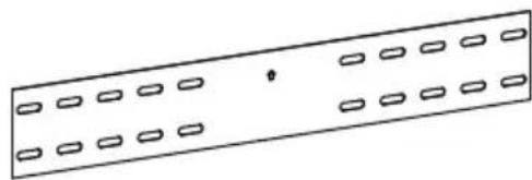
D Plantilla


www.bestbuy.com/bestbuyessentials
For product inquiries, please contact us with the information below:
1-866-597-8427
www.bestbuy.com/bestbuyessentials
BEST BUY ESSENTIALS is a trademark of Best Buy and its affiliated companies.
Distributed by Best Buy Purchasing, LLC
7601 Penn Ave South, Richfield, MN 55423 U.S.A.
©2024 Best Buy. All rights reserved.
www.bestbuy.com/bestbuyessentials
www.bestbuy.com/bestbuyessentials


- BEST BUY ESSENTIALS™
- CONTENTS/TABLE DES MATIÈRES/CONTENIDO ENGLISH....4
- FRANÇAIS....25
- ESPAÑOL 46
- SAFETY INFORMATION INSTRUCTIONS
- CAUTION
- SAFETY WARNINGS
- SAVE THESE INSTRUCTIONS
- FEATURES
- VESA TV SCREW HOLE PATTERNS
- DIMENSIONS
- TOOLS NEEDED
- PACKAGE CONTENTS
- PARTS
- INSTALLATION INSTRUCTIONS
- STEP 1- DETERMINE WHETHER YOUR TV HAS A FLAT, IRREGULAR, OR OBSTRUCTED BACK
- STEP 2 - SELECT SCREWS, WASHERS, AND SPACERS
- FOR A TV WITH A FLAT BACK
- FOR A TV WITH AN IRREGULAR/OBSTRUCTED BACK
- STEP 3 - OPTION 1: ATTACH HARDWARE TO A FLAT BACK TV YOU'LL NEED
- STEP 3 - OPTION 2: ATTACH HARDWARE TO AN IRREGULAR OR OBSTRUCTED BACK TV
- STEP 4 - DETERMINE WALL-MOUNT LOCATION YOU'LL NEED
- STEP 5 - OPTION 2: INSTALL ON A SOLID CONCRETE OR CONCRETE BLOCK WALL
- STEP 6 - MOUNT YOUR TV TO THE WALL PLATE
- STEP 7 - ADJUST THE TILT ANGLE
- ONE-YEAR LIMITED WARRANTY
- DEFINITIONS
- HOW LONG DOES THE COVERAGE LAST
- WHAT DOES THIS WARRANTY COVER
- HOW TO OBTAIN WARRANTY SERVICE
- WHERE IS THE WARRANTY VALID
- WHAT DOES THE WARRANTY NOT COVER
- CUSTOMER INSTRUCTION/EDUCATION
- FRANÇAIS
- INFORMATIONS SUR LA SÉCURITÉ
- ATTENTION
- GARANTIE LIMITÉE D'UN AN
- DESCRIPTION
Brand : Best Buy
Model : BE-TVLTLC
Category : Wall mount