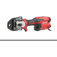
RP 251 - Hydraulic press tool RIDGID - Free user manual and instructions
Find the device manual for free RP 251 RIDGID in PDF.


| Product Type | Hydraulic Press Tool |
| Brand | RIDGID |
| Model | RP 251 |
| Weight (without battery or tools) | 1.62 kg (3.57 lb) |
| Power Supply | Rechargeable 12 V Li-ion battery pack (RIDGID RB-1200 series) |
| Rated Voltage | 10.8 V |
| Piston Force | 24 kN (5,400 lb) |
| Piston Stroke | 30.5 mm (1.2 in) |
| Head Rotation | 360° |
| Duty Cycle | 3 crimps per minute |
| Operating Temperature | -10°C to 50°C (15°F to 122°F) |
| Storage Temperature | 0°C to 45°C (32°F to 113°F) |
| Wireless Connectivity | Yes, via RIDGID Link app (10 m range) |
| LED Lighting | Integrated, lights up when turned on |
| Operating Modes | Normal and Controlled (via app) |
| Auto Shut-off | After 120 seconds of inactivity |
| Compatible Tool Series | Compact (jaws and actuators) |
| Warranty | Lifetime (extended legal warranty covering product lifetime) |
| Cleaning | Wipe with a clean, dry cloth; lubricate the pin with silicone lubricant |
| Firmware Update | Via RIDGID Link app |
| Included Accessories | Carrying case, fabric strap (depending on reference) |
Frequently Asked Questions - RP 251 RIDGID
User questions about RP 251 RIDGID
0 question about this device. Answer the ones you know or ask your own.
Ask a new question about this device
Download the instructions for your Hydraulic press tool in PDF format for free! Find your manual RP 251 - RIDGID and take your electronic device back in hand. On this page are published all the documents necessary for the use of your device. RP 251 by RIDGID.
USER MANUAL RP 251 RIDGID
natural_image
Red and black RIGID utility tool with connecting rod and connecting cap (no visible text or symbols on body)


RIDGID.com/qr/rp251
- Français – 15
General Power Tool Safety Warnings
Work Area Safety 2
Electrical Safety 2
Personal Safety....3
Power Tool Use And Care 3
Battery Tool Use And Care 4
Service....4
Specific Safety Information
Press Tool Safety 4
RIDGID® Contact Information....5
Description....5
Specifications 6
Standard Equipment 7
RIDGID Link App Connection (Wireless Communication)....7
Pre-Operation Inspection....8
Set-Up and Operation....9
Removing/Installing Attachment....9
Preparing Connection 9
Pressing A Fitting With Typical Scissor Jaws.... 10
Pressing A Fitting With Typical Actuator And Press Ring Set 11
Inspecting The Pressed Connection ....11
Cold Weather Operation....12
Storage 12
Maintenance Instructions
Cleaning And Lubrication.... 12
Updating Firmware 12
Troubleshooting 12-13
Service And Repair 13
Optional Equipment 13
Disposal....13
Electromagnetic Compatibility (EMC) 14
FCC/ICES Statement ...... Inside Back Cover
Declaration of Conformity....Inside Back Cover
Lifetime Warranty....Back Cover
Original Instructions - English
RP 251 Press Tool

natural_image
Ridgid electrical measuring tool with labeled components (no readable text beyond branding)
WARNING!
Read this Operator's Manual carefully before using this tool. Failure to understand and follow the contents of this manual may result in electrical shock, fire and/or serious personal injury.
Safety Symbols
In this operator's manual and on the product, safety symbols and signal words are used to communicate important safety information. This section is provided to improve understanding of these signal words and symbols.

DANGER
This is the safety alert symbol. It is used to alert you to potential personal injury hazards. Obey all safety messages that follow this symbol to avoid possible injury or death.
DANGER indicates a hazardous situation which, if not avoided, will result in death or serious injury.
WARNING
WARNING indicates a hazardous situation which, if not avoided, could result in death or serious injury.
CAUTION
CAUTION indicates a hazardous situation which, if not avoided, could result in minor or moderate injury.
NOTICE NOTICE indicates information that relates to the protection of property.

This symbol means read the operator's manual carefully before using the equipment. The operator's manual contains instant information on the safe and proper ion of the equipment.

This symbol means always wear safety glasses with side shields or goggles while using this equipment to reduce the risk of injury.

This symbol indicates this is electrical equipment meets the requirements of the applicable EC directives.
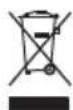
This symbol indicates this is electrical equipment that should not be disposed of with household waste. See "Disposal" section.

This is information symbol and indicates the product information available (including operators' manual) by scanning the content QR code.

This symbol indicates the year of manufacture of the product.

This symbol indicates the risk of hands, fingers or other body parts being crushed.

This symbol indicates the risk of electrical shock.

This symbol indicates that RIDGID® RB-12XXX series batteries (such as the RIDGID RB1225R and RB-1225) can be used with this equipment.
General Power Tool Safety Warnings\*
WARNING
Read all safety warnings, instructions, illustrations and specifications provided with this power tool. Failure to follow all instructions listed below may result in electric shock, fire and/or serious injury.
SAVE ALL WARNINGS AND INSTRUCTIONS FOR FUTURE REFERENCE!
The term "power tool" in the warnings refers to your mains-operated (corded) power tool or battery-operated (cordless) power tool.
Work Area Safety
- Keep work area clean and well lit. Cluttered or dark areas invite accidents.
- Do not operate power tools in explosive atmospheres, such as in the presence of flammable liquids, gases or dust. Power tools create sparks which may ignite the dust or fumes.
- Keep children and bystanders away while operating a power tool. Distractions can cause you to lose control.
Electrical Safety
- Power tool plugs must match the outlet. Never modify the plug in any way. Do not use any adapter plugs with earthed (grounded) power tools. Unmodified plugs and matching outlets will reduce risk of electric shock.
- Avoid body contact with earthed or grounded surfaces, such as pipes, radiators, ranges and refrigerators. There is
an increased risk of electric shock if your body is earthed or grounded.
- Do not expose power tools to rain or wet conditions. Water entering a power tool will increase the risk of electric shock.
- Do not abuse the cord. Never use the cord for carrying, pulling or unplugging the power tool. Keep cord away from heat, oil, sharp edges or moving parts. Damaged or entangled cords increase the risk of electric shock.
- When operating a power tool outdoors, use an extension cord suitable for outdoor use. Use of a cord suitable for outdoor use reduces the risk of electric shock.
- If operating a power tool in a damp location is unavoidable, use a Ground Fault Circuit Interrupter (GFCI) protected supply. Use of a GFCI reduces the risk of electric shock.
- If operating a power tool in a damp location is unavoidable, use a Residual Current Device (RCD) protected supply. Use of a RCD reduces the risk of electric shock.
- It is recommended that the tool always be supplied via a Residual Current Device having a residual current of 30mA or less.
Personal Safety
- Stay alert, watch what you are doing and use common sense when operating a power tool. Do not use a power tool while you are tired or under the influence of drugs, alcohol or medication. A moment of inattention while operating power tools may result in serious personal injury.
- Use personal protective equipment. Always wear eye protection. Protective equipment such as dust mask, non-skid safety shoes, hard hat, or hearing protection used for appropriate conditions will reduce personal injuries.
- Prevent unintentional starting. Ensure the switch is in the OFF-position before connecting to power source and/or battery pack, picking up or carrying the tool. Carrying power tools with your finger on the switch or energizing power tools that have the switch ON invites accidents.
- Remove any adjusting key or wrench before turning the power tool ON. A
wrench or a key left attached to a rotating part of the power tool may result in personal injury.
- Do not overreach. Keep proper footing and balance at all times. This enables better control of the power tool in unexpected situations.
- Dress properly. Do not wear loose clothing or jewelry. Keep your hair, clothing and gloves away from moving parts. Loose clothes, jewelry or long hair can be caught in moving parts.
- If devices are provided for the connection of dust extraction and collection facilities, ensure these are connected and properly used. Use of dust collection can reduce dust-related hazards.
- Do not let familiarity gained from frequent use of tools allow you to become complacent and ignore tool safety principles. A careless action can cause severe injury within a fraction of a second.
Power Tool Use And Care
- Do not force the power tool. Use the correct power tool for your application. The correct power tool will do the job better and safer at the rate for which it was designed.
- Do not use the power tool if the switch does not turn it ON and OFF. Any power tool that cannot be controlled with the switch is dangerous and must be repaired.
- Disconnect the plug from the power source and/or remove the battery pack, if detachable, from the power tool before making any adjustments, changing accessories, or storing power tools. Such preventive safety measures reduce the risk of starting the power tool accidentally.
- Store idle power tools out of the reach of children and do not allow persons unfamiliar with the power tool or these instructions to operate the power tool. Power tools are dangerous in the hands of untrained users.
-
Maintain power tools and accessories. Check for misalignment or binding of moving parts, breakage of parts and any other condition that may affect the power tool's operation. If damaged, have the power tool repaired before use. Many accidents are caused by poorly maintained power tools.
-
Keep cutting tools sharp and clean. Properly maintained cutting tools with sharp cutting edges are less likely to bind and are easier to control.
- Use the power tool, accessories and tool bits etc. in accordance with these instructions, taking into account the working conditions and the work to be performed. Use of the power tool for operations different from those intended could result in a hazardous situation.
- Keep handles and grasping surfaces dry, clean and free from oil and grease. Slippery handles and grasping surfaces do not allow for safe handling and control of the tool in unexpected situations.
Battery Tool Use And Care
- Recharge only with the charger specified by the manufacturer. A charger that is suitable for one type of battery pack may create a risk of fire when used with another battery pack.
- Use power tools only with specifically designated battery packs. Use of any other battery packs may create a risk of injury and fire.
- When battery pack is not in use, keep it away from other metal objects, like paper clips, coins, keys, nails, screws or other small metal objects that can make a connection from one terminal to another. Shorting the battery terminals together may cause burns or a fire.
- Under abusive conditions, liquid may be ejected from the battery; avoid contact. If contact accidentally occurs, flush with water. If liquid contacts eyes, additionally seek medical help. Liquid ejected from the battery may cause irritation or burns.
- Do not use a battery pack or tool that is damaged or modified. Damaged or modified batteries may exhibit unpredictable behavior resulting in fire, explosion or risk of injury.
- Do not expose a battery pack or tool to fire or excessive temperature. Exposure to fire or temperature above 265°F (130°C) may cause explosion.
- Follow all charging instructions and do not charge the battery pack or tool outside the temperature range specified in the instructions. Charging improper-
ly or at temperatures outside the speci- fied range may damage the battery and increase the risk of fire.
Service
- Have your power tool serviced by a qualified repair person using only identical replacement parts. This will ensure that the safety of the power tool is maintained.
- Never service damaged battery packs. Service of battery packs should only be performed by the manufacturer or authorized service providers.
Specific Safety Information
WARNING
This section contains important safety information that is specific to this tool.
Read these precautions carefully before using the press tools to reduce the risk of electrical shock, or other serious injury.
SAVE ALL WARNINGS AND INSTRUCTIONS FOR FUTURE REFERENCE!
A compartment in the tool carrying case is included to keep this manual with the tool for use by the operator.
Press Tool Safety
- Keep your fingers and hands away from pressing attachments during press cycle. Your fingers or hands can be crushed, fractured or amputated if they become caught between the attachment or between these components and any other object.
- Never attempt to repair worn or damaged pressing attachments. Discard the entire worn or damaged attachment. An attachment that has been welded, ground, drilled or modified in any manner can shatter during pressing resulting in serious injury. Failure to replace the entire pressing attachment may result in component failure and serious injury.
- Large forces are generated during product use that can break or throw parts and cause injury. Keep unnecessary personnel away from work area. Stand clear
during use and wear appropriate protective equipment, including eye protection.
- One person must control work process and tool operation. To reduce the risk of injury, only the operator should be in the area when the tool is running.
- Only use RIDGID® Press Tools with appropriate RIDGID or RIDGID approved Pressing attachments. Other uses or modifying the Press Tools for other applications may damage the press tool, damage the attachments and/or cause personal injury.
- Use proper tool, attachment and fitting combinations. Improper combinations can result in an incomplete joint, which increase the risk of leaks, equipment damage and injury.
- Do not modify tool. Modifying the tool in any manner may result in personal injury and voidance of the tool's warranty.
- Before operating a RIDGID® Press Tool, read and understand:
- This operator's manual
- The instructions for any attachments being used
– The battery/charger manual - The fitting manufacturer's installation instructions
- The instructions for any other equipment or material used with this tool
Failure to follow all instructions and warnings may result in property damage and/or serious injury.
RIDGID Contact Information
If you have any question concerning this RIDGID® product:
- Contact your local RIDGID distributor.
- Visit RIDGID.com to find your local RIDGID contact point.
- Contact Ridge Tool Technical Service Department at ProToolsTechService@Emerson.com or in the U.S. and Canada call 844-789-8665.
Description
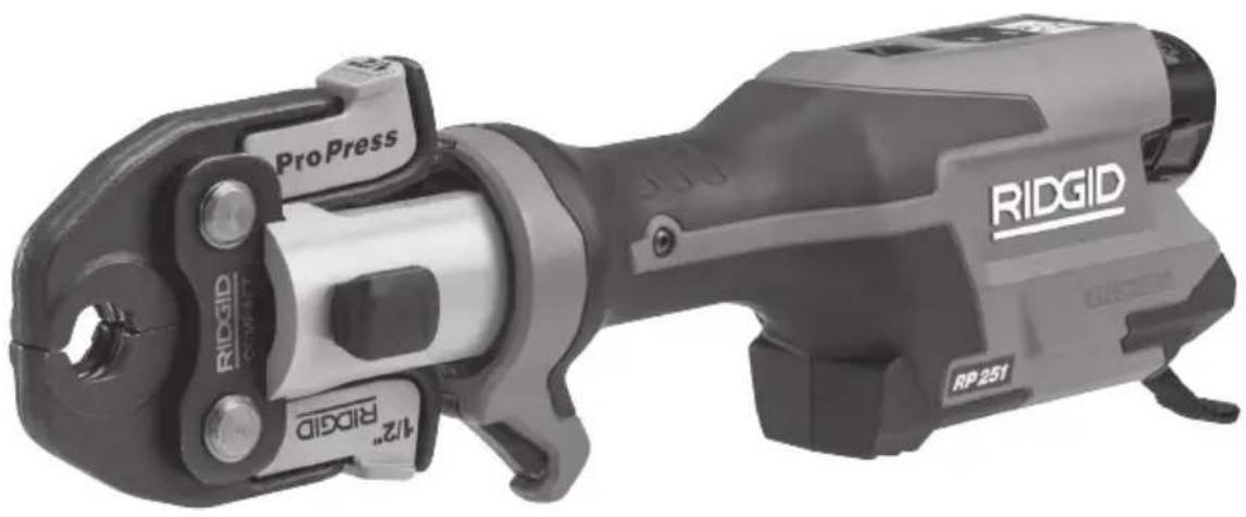
The RIDGID ^® RP 251 Press Tool, when used with appropriate attachments, is designed to mechanically press fittings onto tubing to create a water-tight and permanent seal, such as for plumbing, heating, air conditioning, and refrigeration applications.
When the trigger/run switch on the press tool is depressed, an internal electric motor powers a hydraulic pump which sends fluid into the cylinder of the tool, moving the ram forward and applying force to the attachment, pressing the fitting. The press cycle takes approximately 4 seconds. Once the cycle begins to deform a fitting, it will automatically continue until completion, even if the trigger/run switch is released.
The tool includes a second operating mode ("Control Mode") that can be turned on using the RIDGID Link App. Control Mode allows the fitting to be engaged prior to pressing to allow confirmation of proper alignment of the attachment, fitting and tube.
The Tool Status Lights indicate things such as tool status, battery status, maintenance required, or improper temperature. A work light turns on when the trigger/run switch is depressed to power up the tool and helps illuminate the work area. The tool switches OFF after 120 seconds of inactivity.
The head can be rotated 360^ for better access in tight spaces. The tool is supplied with fabric loops that can be used with appropriate attachments such as shoulder straps or tie off lines.
The press tool include wireless technology to allow connection to smart phones and tablets. See “RIDGID Link App Connection (Wireless Communication)” section for details.
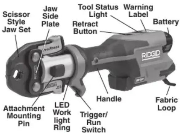
Figure 1A – RIDGID RP 251 Press Tool
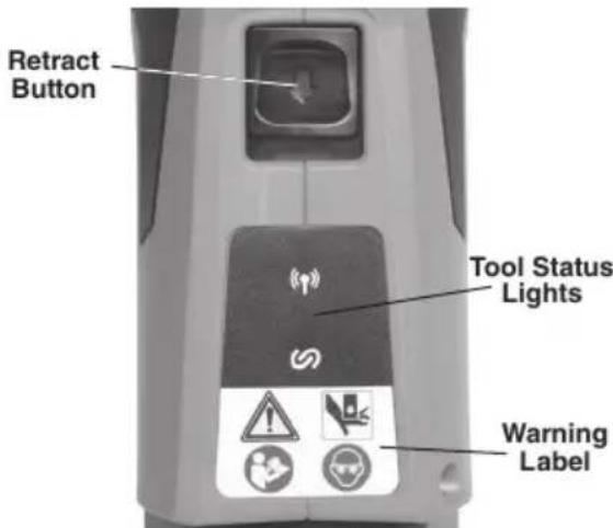
Figure 1B – Status Lights/Warning Label
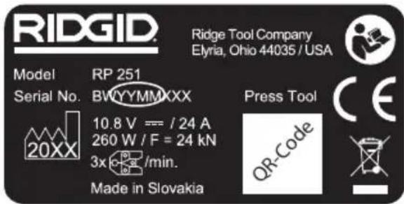
Figure 2 – Machine Serial Number - Circled digits indicate the year and month of the manufacture. (YY = year, MM = month,)
Specifications
Attachments ..... RIDGID Compact Series
Stroke Length.....1.2" (30.5 mm)
Ram Force ..... 5,400 lbs. (24 kN)
Motor
Voltage ...... 10,8 V DC rated
Amperage..... 24 A
Power 260 Watts
Head Rotation ... 360°
Duty Cycle...... 3 Press /min.
Power Supply .... 12V Li-ion Rechargeable
Battery Pack (RIDGID
RB-1200 Series)
Wireless Connection
Range.... 33 ft. (10 m)
Permissible
Humidity ...... 80%maximum
Operating Temperature
Range..... 15° F to 122° F
(-10°C to 50°C)
Storage
Temperature..... 32° F to 113° F
(0°C to 45°C)
Weight (no battery/
Attachment)...... 3.57 lbs. (1.62 kg)
Dimensions (no battery/
Attachment)...... 13" x 4.3" x 2.6"
(330 mm x 109 mm x 66 mm)
Sound Pressure
(L_PA)^* < 67.8 dB(A), K=2.5 dB(A)
Sound Power
(L_PW)^* ....<75.8 dB(A), K=2.5 dB(A)
Vibration*....< 0.71 m/s², K=1.5 m/s²
* Sound and Vibration measurements are measured in accordance with a standardized test per Standard EN 62481-1.
- Vibration levels may be used for comparison with other tools and for preliminary assessment of exposure.
- Sound and vibration emissions may vary due to your location and specific use of these tools.
- Daily exposure levels for sound and vibration need
| Control Marking | Description | |
| Trigger/Run Switch | — | Single press/release of trigger/run switch will power up the tool (LED work light ring and Tool status light illuminated). The tool can now be used. Tool will stay powered up and ready to use for 2 minutes. If the lights turn off, the switch will need to be pressed again to allow tool to run.Normal Mode:Depress run switch to start press cycle, release when tool locks on.Normal mode is factory setting.Control Mode:Depress run switch to engage attachment on workpiece. Make adjustments as necessary. Press the run switch again to start press cycle, release when tool locks on.Releasing the switch will not stop the tool once it has locked on. This assures consistent, repeatable press connection integrity.Mode can be changed with RIDGID Link App, see “RIDGID Link App Connection (Wireless Communication)” section. |
| Retract Button | Allows tool to be released without completing press. If used, press connection is not complete and must be repeated. | |
| Attachment Mounting Pin | — | Holds attachment to tool. Must be fully inserted for tool to operate |
Figure 3 – Controls Chart
| Icon | Solid Light Blinking Light  |  | Description | |
 | Blue | Connection to RIDGID Link app possible. | ||
| Blue | Connection to RIDGID Link app established. | |||
 | Green | Tool is in “Normal Mode”, standby, ready to operate. | ||
| Blue | Tool is in “Control Mode”, standby, ready to operate. | |||
| Green | Press cycle finished. | |||
| Red (4 Seconds) | Press cycle interrupted (valve opened manually / too early before pressure reached). Confirm proper set-up and restart use. Consult RIDGID Link app for more information. | |||
| Red | Attachment mounting pin is not fully inserted. Tool will not operate. Fully insert pin. If lights still on, have tool serviced. | |||
| Red | Machine has malfunctioned and will not operate. Remove battery and allow Machine to rest, then reinsert battery. If light still ON, have machine serviced. Consult RIDGID Link app for more information. | |||
| Yellow | Battery low. Recharge battery/Insert fully charged battery. | |||
| Red + Yellow | Battery low. Tool will not operate. Recharge battery/Insert fully charged battery. | |||
 | Yellow | Tool near locking with “Theft protection”. The user can unlock the tool through the RIDGID Link App. If it is not your tool, return it to the Service Center or original user. | ||
 | Yellow | |||
 | Yellow | Tool locked with “Theft protection”. The user can unlock the tool through the RIDGID Link App. If it is not your tool, return it to the Service Center or original user. | ||
 | Red | |||
Figure 4 – Tool Status Lights
to be evaluated for each application and appropriate safety measures taken when needed. Evaluation of exposure levels should consider the time a tool is switched OFF and not in use. This may significantly reduce the exposure level over the total working period.
Standard Equipment
Refer to the RIDGID catalog for details on equipment supplied with specific tool catalog numbers.
NOTE! RIDGID press tool attachments are offered in two "series":
- Standard Series
- Compact Series
These attachment series are not interchangeable. Standard series attachments will only work with standard series tools (RP 350, RP 351, RP 342-XL, RP 340, RP 330, 320-E, CT-400). Compact series attachments will only work with compact series tools (RP 251, RP 240, RP 241, RP 200, RP 210, 100B).
▲ WARNING Only use RIDGID Press Tools and RIDGID press tool attachments when specified by the fitting manufacturer for use with their system. Use of incorrect press tools and/or attachments for a system can cause system leaks, damage the press tool or
attachment, void warranties or cause severe personal injury.
NOTICE Selection of a appropriate materials and joining methods is the responsibility of the system designer and/or installer. Before any installation is attempted, careful evaluation of the specific service environment, including chemical environment and service temperature, should be completed. Consult Press Fitting System manufacturer for selection information.
Contact the fitting manufacturer for specific information on their system, including compatible tubing, materials, installation instructions, minimum distance between fittings, seal material, inspection, testing, etc. Incorrect installation can cause system leaks and extensive property damage.
RIDGID Link App Connection (Wireless Communication)
The RIDGID® RP-251 Press Tool includes wireless technology allowing communication to properly equipped smartphones or tablets
("devices") running iOS or Android operating systems. This allows the user to review and download stored job data and create reports and update firmware. For the best user experience, it is recommended that firmware be kept up to date. Check, and if needed, update your tool firmware before the first use of the product and on a regular basis thereafter.
-
Download the appropriate RIDGID® Link app to your device by going to RIDGID.com/apps, the Google Play Store or the Apple App Store.
-
When the tool is ON, the (p) Light will blink blue when connection to a device is possible. See Figure 4.
-
Find the RIDGID Link App icon on your device and launch the app by selecting the icon. Via the app, search for nearby tools and select the desired RIDGID tool. Refer to your device instructions for specific information on how to connect via wireless technology. Once connected, the Light will be lit solid blue.
After the initial pairing, most devices will automatically connect to the machine when the wireless technology is active and in range and if device settings are configured to do so. Machine should be less than 33 ft. (10 m) from the device to be detected. Any obstacle between the machine and device can reduce the operational range.
-
After pairing, the system will check for firmware updates. Follow the app instructions to initiate the update if needed. Do not operate the tool while updates are in progress. While a firmware update is in progress, no LED's will be ON. Check app instructions to confirm the new firmware is installed.
-
Follow the app instructions for use. Do not let the use of the app distract you from monitoring the process. Inattention to the process can cause you to lose control.
-
The wireless communication turns OFF when the main power removed. Turn wireless communication off on the device to reduce device battery drain.
Pre-Operation Inspection
WARNING
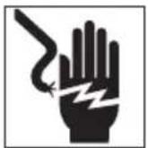
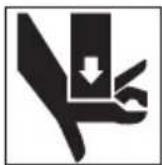
Daily before use, inspect your press tool and attachments. Correct any problems to reduce the risk of serious injury from electric shock, crushing injures, attachment failure and other causes, and prevent tool damage.
- Remove battery from tool.
-
Clean any oil, grease or dirt from the equipment, especially the handles and controls. This aids inspection and helps to prevent the tool or controls from slipping from your grip.
-
Inspect the press tool for:
• Proper assembly, maintenance and completeness.
- Any broken, worn, missing, misaligned or binding parts. Confirm fabric loops are in good condition.
- Smooth movement of attachment mounting pin between the fully open and fully closed position. Pin should lock into each position. Confirm that the trigger/run switch moves freely and does not bind or stick.
• Presence and readability of warning label (Figure 1A or 1B).
- Any other condition which may prevent safe and normal operation.
Do not use the press tool until problems have been repaired.
-
Inspect and maintain tool attachments per their instructions. Remove attachment from the tool. Confirm that attachments are in good condition and clearly marked as to use.
-
Inspect and maintain any other equipment being used per its instructions to make sure it is functioning properly.
Set-Up and Operation
WARNING


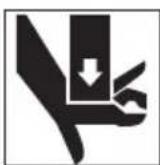
Keep your fingers and hands away from pressing attachments during press cycle. Your fingers or hands can be crushed, fractured or amputated in the attachment or between the attachment and other objects (such as the tool, workpiece and surroundings).
Large forces are generated during product use that can break or throw parts and cause injury. Stand clear during use and wear appropriate protective equipment, including eye protection.
Use proper tool, attachment and fitting combinations. Improper combinations can result in an incomplete press connection, which increases the risk of leaks, equipment damage and injury.
Follow Set-up and Operation to reduce the risk of injury from crushing and other causes and to prevent tool damage.
-
Confirm appropriate work area (See General Power Tool Safety Warnings). Operate in a clear, level, stable, dry location. Do not use tool while standing in water.
-
Inspect the work to be done and determine the correct RIDGID tool and RIDGID attachment for the application per their specifications. Using incorrect equipment for an application can cause injury, damage the tool and make incomplete connections.
-
Confirm all equipment has been inspected and set up as directed in their instructions.
Removing/Installing Attachment
-
Remove battery from tool.
-
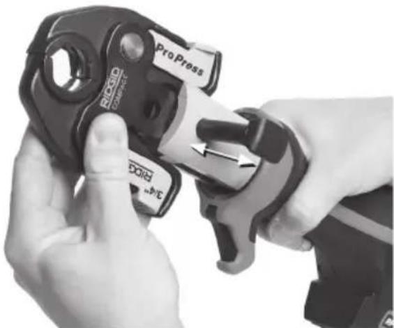
Fully open the attachment mounting pin. Remove/insert the appropriate attachment (Figure 5).
-
Fully close the attachment mounting pin until it locks into the closed position. Attachment mounting pin must be fully closed to prevent tool damage during use.
NOTE: Do not operate tool without the attachment in place, this can damage the tool.
natural_image
Close-up of hands using a ProPress tool to adjust a mechanical component (no text or symbols visible)Figure 5 – Attachment Mounting Pin
Preparing Connection
NOTICE These instructions are generalized practices for several types of press tool attachments. Always follow the specific instructions for the press tool attachment being used and the fitting manufacturers' specific installation instructions to reduce the risk of improper press connections and extensive property damage.
-
Prepare the press connection according to the fitting manufacturer's instructions.
-
With dry hands, insert a fully charged battery into tool.
-
After inserting the battery, the tool will not be ON until the trigger is pressed and released to power up the tool. When powered up the LED work light ring will turn ON and the Tool status light will be Green or Blue depending on Mode. The tool can now be used.
-
After 120 sec of no operation, the tool will power down until the trigger is pressed to power up the tool again. The tool is powered down if the LED work light ring is OFF. The power up trigger press will not activate the tool; another trigger press is required to start the tool cycle.
Pressing A Fitting With Typical Scissor Jaws
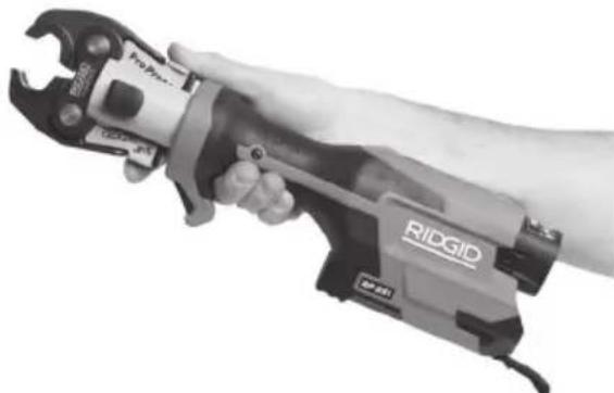
- Squeeze jaw arms to open jaws. In many cases this can be done with one hand (see Figure 6).
natural_image
Hand holding an adjustable RIGID wrench, no visible text or symbols on the tool itselfFigure 6 – Opening Jaw with One Hand
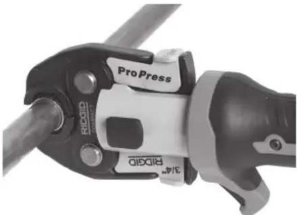
- Place open jaws around fitting (Figure 7). Properly align jaw press profile with contour of the fitting as specified in Fitting Manufacturer's Installation Instructions. Release jaw arms to close jaws around fitting. Do not hang jaw set from fitting. Tool could unexpectedly drop and cause serious injury or death.
natural_image
Close-up of a ProPress and RIGSID crimping tool handle (no text or symbols visible)Figure 7 – Placing Scissor-Style Jaws Around Fitting
natural_image
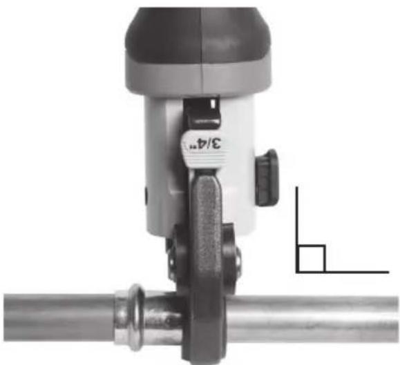
Close-up of a mechanical device with a 3/4" label and a small L-shaped annotation (no readable text or symbols)Figure 8 – Jaws Square to Fitting
- Confirm jaw is appropriately placed and square to fitting (Figure 8). Keep fingers and hands away from the jaws to avoid
crushing injuries in jaws or between jaws and surroundings.
If the tool work light is OFF, power up the tool by depressing and releasing the tool switch one time. The tool is now ready to make a press.
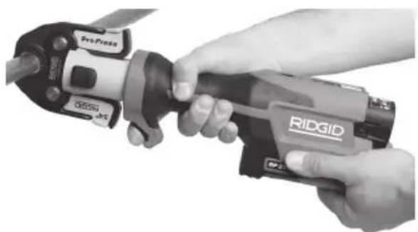
Normal Mode: Depress the trigger/run switch (Figure 9). Once the tool cycle begins and the rollers contact the jaw arms, the tool will lock-on and automatically complete the cycle. Releasing the switch will not stop the tool once it has locked on. This assures consistent, repeatable press connection integrity.
Control Mode: Depress the trigger/run switch (Figure 9). The jaws will engage the fitting but the press connection is not made. Make adjustments as necessary. Press the run switch again, the tool will lock-on and automatically complete the cycle. Releasing the switch will not stop the tool once it has locked on. This assures consistent, repeatable press connection integrity.
If tool must be removed before a connection is completed, release the trigger/run switch, depress the retract button (Figures 1A &1B).
NOTICE Any time retract button is depressed, press is NOT complete and the connection must be pressed again to ensure completion. If the tool malfunctions during operation, use this procedure.
natural_image
Close-up of hands using a RIDGID power tool to handle a cylindrical component (no visible text or symbols)Figure 9 – Pressing the Fitting
- Release the trigger/run switch.
- Squeeze jaw arms to open jaws.
- Remove jaw from fitting. Avoid sharp edges that may have formed on fitting during pressing operation.
- When operation is complete, remove battery from tool.
Pressing A Fitting With Typical Actuator And Press Ring Set
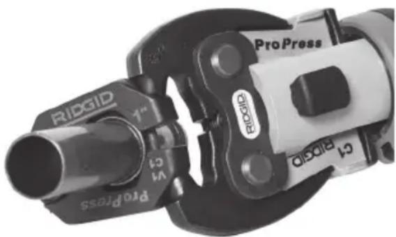
- Open ring and place around fitting. Properly align ring press profile with contour of the fitting as specified in Fitting Manufacturer's Installation Instructions. Release ring to close around fitting (Figure 10).
- Confirm appropriate actuator is properly installed in tool. Squeeze actuator arms to open the actuator tips. Align actuator tips with ring pockets. Release actuator arms and fully engage actuator tips into ring pockets (Figure 10). Misaligning actuator tip to ring pocket can damage the ring or actuator during pressing. Do not hang tool and actuator from press ring. Tool could unexpectedly drop and cause serious injury or death.
natural_image
Close-up of a ProPress crimping tool with visible branding and pipe specifications (no readable text beyond branding)Figure 10 - Attaching Actuator to Press Ring
- Confirm ring is appropriately placed and square to fitting. Keep fingers and hands away from the actuator and ring to avoid crushing injuries in attachment or between attachment and surroundings.
If the tool work light is OFF, wake up the tool by depressing and releasing the tool switch one time. The tool is now ready to make a press.
Normal Mode: Depress the trigger/run switch (Figure 1). Once the tool cycle begins and the rollers contact the jaw arms, the tool will lock-on and automatically complete the cycle. Releasing the switch will not stop the tool once it has locked on. This assures consistent, repeatable press connection integrity.
Control Mode: Depress the trigger/run switch (Figure 1). The jaws will engage the fitting but the press connection is not made. Make adjustments as necessary. Press the run switch again, the tool will lock-on and automatically complete
the cycle. Releasing the switch will not stop the tool once it has locked on. This assures consistent, repeatable press connection integrity.
If tool must be removed before a connection is completed, release the trigger/run switch, depress the retract button (Figure 1).
A NOTICE retract button is depressed, press is NOT complete and the connection must be pressed again to ensure completion. If the tool malfunctions during operation, use this procedure.
-
Release the trigger/run switch.
-
Squeeze actuator arms to open actuator. Remove actuator from ring.
-
Remove ring from fitting. Avoid sharp edges that may have formed on fitting during pressing operation.
-
When operation is complete. Remove battery from tool.
Inspecting The Pressed Connection
- Inspect the pressed fitting for:
• Full insertion of tube into fitting.
- Excessive misalignment of the tubes. A slight amount of misalignment at a press connection is considered normal.
- Incorrect attachment alignment with the fitting contour. Distorted or deformed fitting.
- Any other issues per the fitting manufacturer. This could include the removal of a control ring or decal (used to indicate the connection has not yet been pressed).
If any issues are found, remove fitting and install a new press connection.
- Test the press connection in accordance with connector manufacturer instructions, normal practice and applicable codes.
Cold Weather Operation
As temperature drops, hydraulic fluid thickens and battery performance degrades. To reduce the risk of improper operation, the RP 251 Press Tool will not operate outside of the specification temperature range as indicated by the tool status lights (Figure 5).
When ambient conditions are outside the specification temperature range, keep the
tool and batteries in a conditioned space until ready to use.
Storage
Remove battery from the press tool. Store press tool, attachments and battery in case. Avoid storing in extreme heat or cold. The tool will not turn ON if the tool is outside the specification range.
Store tool in a dry, secured, locked area that ⚠ WARNING is out of reach of children and people unfamiliar with the press tool. The tool is dangerous in the hands of untrained users.
Maintenance Instructions
WARNING
Make sure the battery is removed from
tool before performing maintenance or making any adjustment.
Cleaning And Lubrication
- Wipe the tool clean daily with a clean dry cloth.
- Inspect the attachment mounting pin and lubricate the pin with silicone lubricant as needed.
- Check return springs in attachments with each use. Attachments should open and close freely with only moderate finger effort required.
Updating Firmware
For the best user experience, it is recommended that firmware be kept up to date. Check, and if needed, update your tool firmware before the first use of the product and on a regular basis thereafter. See RIDGID Link App Connection section.
Troubleshooting
| PROBLEM POSSIBLE REASON SOLUTION | ||
| Tool will not turn ON when trigger/run switch is pressed. | Battery is completely discharged or battery has failed. | Insert fully charged battery/replace battery. |
| Battery not properly inserted into handle of tool. | Check to assure battery is fully inserted. | |
| Attachment is locked onto fitting. | Press connection was not successfully completed. | Push pressure retract button to remove jaws from fitting. Inspect and re-press fitting. |
| The pressed connections produced are not complete. | Used wrong jaw for the tube size or material. | Install the correct attachment. |
| The tool was not square to the tube. | Redo the press connection with new fitting and new tube. Make sure that the tool is square to the tube. | |
| Attachment press contour was not aligned with the fitting contour. | Redo the press connection with fitting and new tube. Make sure the attachment press contour is aligned with the fitting contour.. | |
| Tool is in need of repair. | See Contact Information for nearest RIDGID Authorized Independent Service center. | |
| Oil leaks from tool. | Seal or mechanical problems. | |
| Motor runs but tool will not complete a cycle. | Oil level low. | See Contact Information for nearest RIDGID Authorized Independent Service center. |
| Tool stops during operation. | Oil level low. | |
| See Figure 5 for Tool Status Lights.See RIDGID Link App Connection section for Firmware updates. | ||
Service And Repair
WARNING
Improper service or repair can make machine unsafe to operate.
Service and repair on the RP 251 Press Tool must be performed by a RIDGID Authorized Independent Press Tool Service Center.
For information on your nearest RIDGID Authorized Independent Service Center or any service or repair questions see Contact Information section in this manual.
Optional Equipment
WARNING
To reduce the risk of injury, only use equipment specifically designed and recommended for use with the RP 251s Press Tool, such as listed below.
| Catalog No. | Description |
| 78258 | Carry Case, RP 251 |
Battery Pack
| Catalog No. | Description | Capacity |
| 55183 R | B-1225R 12V 2.5Ah Li-Ion |
Battery will work with any catalog number RBC-121 Battery Charger.
Chargers and Cords
| Catalog No. | Description | Region Type | Plug |
| 55193 | Charger | USA, Canada and Mexico | A |
| 55198 | Charger | Europe | C |
| 55203 | Charger | China | A |
| 55208 | Charger | Australia & Latin America | I |
| 55213 | Charger | Japan | A |
| 55218 | Charger | United Kingdom | G |
| 44798 | Charger Cord | North America A | |
| 44808 | Charger Cord | Europe | C |
| 44803 | Charger Cord | China | A |
| 44813 | Charger Cord | Australia & LA | I |
| 44818 | Charger Cord | Japan | A |
| 44828 | Charger Cord | United Kingdom | G |
For a complete listing of RIDGID® equipment available for this tool, see the Ridge Tool Catalog online at RIDGID.com or see Contact Information.
Disposal
Parts of these tools contain valuable materials and can be recycled. There are companies that specialize in recycling that may be found locally. Dispose of the components in compliance with all applicable regulations. Contact your local waste management authority for more information
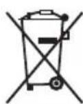
For EC Countries: Do not dispose of electrical equipment with household waste!
According to the European Guideline 2012/19/EU for Waste Electrical and Electronic Equipment and its implementation into national legislation, electrical equipment that is no longer usable must be collected separately and disposed of in an environmentally correct manner.
Electromagnetic Compatibility (EMC)
The term electromagnetic compatibility is taken to mean the capability of the product to function smoothly in an environment where electromagnetic radiation and electrostatic discharges are present and without causing electromagnetic interference to other equipment.
NOTICE These tools conform to all applicable EMC standards. However, the possibility of them causing interference in other devices cannot be precluded. All EMC related standards that have been tested are called out in the tool's technical document.
Sertisseuse RP 251
natural_image
Ridgid irrigation tool with attached pipe fitting and brand logo (no text-heavy elements)AVERTISSEMENT
Dimensions (sans piles
ni outils)....13" x 4,3" x 2,6"
(330 mm x 109 mm x 66 mm)
Pression sonore
(L_PA)^* ....<67,8 dB(A), K=2,5 dB(A)
Puissance sonore
(L_PW)^* .... < 75,8 dB(A), K=2,5 dB(A)
Vibrations*......< 0,71 m/s ^2 , K=1,5 m/s ^2
natural_image
Close-up of hands holding a ProPress crimping tool, showing mechanical components and a directional arrow (no text or symbols on the tool itself)natural_image
Hand holding an adjustable RIOGID wrench, no visible text or symbols on the tool itselfnatural_image
Close-up of a ProPress tool with visible internal components and branding (no readable text beyond branding)natural_image
Close-up of a mechanical device with a lever and handle, mounted on a metal pipe (no visible text or symbols)natural_image
Close-up of hands using a RIDGID power tool to handle a cylindrical component (no visible text or symbols)Figure 9 – Sertissage du raccord
natural_image
Close-up of a mechanical clamp or crimping tool with visible branding and no readable text or symbolsnatural_image
Close-up of hands holding a RIOG connector with a directional arrow indicating movement (no text or symbols on the device itself)natural_image
Hand holding an adjustable RIOGID wrench, no visible text or symbols on the tool itselfnatural_image
Close-up of a ProPress tool with visible branding and mechanical components (no readable text beyond branding)natural_image
Close-up of a mechanical device with a 3/4" label and a separate L-shaped measurement line (no text or symbols on the device itself)natural_image
Close-up of hands using a RIDGID power tool to handle a mechanical component (no visible text or symbols)Figura 9 – Selladura del acoplamiento
natural_image
Close-up of a ProPress crimping tool with visible branding and pipe specifications (no readable text beyond branding)This device complies with Part 15 of the FCC Rules. Operation is subject to the following two conditions:
- This device may not cause harmful interference.
- This device must accept any interference received, including interference that may cause undesired operation.
Modifications not expressly approved by this company could void the user's authority to operate the equipment.
NOTE: This equipment has been tested and found to comply with the limits for a Class A digital device, pursuant to part 15 of the FCC Rules. These limits are designed to provide reasonable protection against harmful interference when the equipment is operated in a commercial environment. This equipment generates, uses, and can radiate radio frequency energy and, if not installed and used in accordance with the instruction manual, may cause harmful interference to radio communications. Operation of this equipment in a residential area is likely to cause harmful interference in which case the user will be required to correct the interference at his own expense.
This product complies with the Canadian ICES-003 Class A specifications. See Declaration label on tool.
RIDGE TOOL COMPANY Ridge Tool Europe NV
EU DECLARATION OF CONFORMITY
We declare that the machines listed above, when used in accordance with the operator's manual, meet the relevant requirements of the Directives and Standards listed below.
DÉCLARATION DE CONFORMITÉ UE
Complies with UL 62841-1
CSA C22.2 No.62841-1
47CFR15B15.107/15.109.
47CFR15C 15.205/15.209/15.247, ICES-003 issue 7

UK Importer
Ridge Tool UK (RIDGID)
70 Gracechurch Street
London EC3V 0HR, UK

Signature: Kond.f
Qualification: V.P. Engineering
Date: 06/20/2024
What is covered
RIDGID ^x tools are warranted to be free of defects in workmanship and material.
How long coverage lasts
This warranty lasts for the lifetime of the RIDGID ^™ tool. Warranty coverage ends when the product becomes unusable for reasons other than defects in workmanship or material.
How you can get service
To obtain the benefit of this warranty, deliver via prepaid transportation the complete product to RIDGID c/o Emerson Professional Tools, LLC in, Elyria, Ohio, or any RIDGID® AUTHORIZED INDEPENDENT SERVICE CENTER. Pipe wrenches and other hand tools should be returned to the place of purchase.
What we will do to correct problems
Warranted products will be repaired or replaced, at RIDGID's option, and returned at no charge; or, if after three attempts to repair or replace during the warranty period the product is still defective, you can elect to receive a full refund of your purchase price.
What is not covered
Failures due to misuse, abuse or normal wear and tear are not covered by this warranty. Seller is not responsible for any incidental or consequential damages.
How local law relates to the warranty
Some states do not allow the exclusion or limitation of incidental or consequential damages, so the above limitation or exclusion may not apply to you. This warranty gives you specific rights, and you may also have other rights, which vary, from state to state, province to province, or country to country.
No other express warranty applies
This FULL LIFETIME WARRANTY is the sole and exclusive warranty for RIDGID* products. No employee, agent, dealer, or other person is authorized to alter this warranty or make any other warranty on behalf of the RIDGE TOOL COMPANY.
To obtain further warranty information on your product please visit www.RIDGID.com/us/en/warranty

Parts are available online at Store.RIDGID.com
RIDGID
Emerson Professional Tools, LLC
400 Clark Street
Elyria, Ohio 44035-6001
U.S.A.
Ce qui est couvert
- General Power Tool Safety Warnings
- Specific Safety Information
- Maintenance Instructions
- RP 251 Press Tool
- WARNING!
- Safety Symbols
- DANGER
- WARNING
- CAUTION
- General Power Tool Safety Warnings\*
- SAVE ALL WARNINGS AND INSTRUCTIONS FOR FUTURE REFERENCE!
- Work Area Safety
- Electrical Safety
- Personal Safety
- Power Tool Use And Care
- Battery Tool Use And Care
- Service
- Press Tool Safety
- RIDGID Contact Information
- Description
- Specifications
- Standard Equipment
- RIDGID Link App Connection (Wireless Communication)
- Pre-Operation Inspection
- Set-Up and Operation
- Removing/Installing Attachment
- Preparing Connection
- Pressing A Fitting With Typical Scissor Jaws
- Pressing A Fitting With Typical Actuator And Press Ring Set
- Inspecting The Pressed Connection
- Cold Weather Operation
- Storage
- Make sure the battery is removed from
- tool before performing maintenance or making any adjustment.
- Cleaning And Lubrication
- Updating Firmware
- Service And Repair
- Optional Equipment
- Disposal
- Electromagnetic Compatibility (EMC)
- Sertisseuse RP 251
- AVERTISSEMENT
- EU DECLARATION OF CONFORMITY
- DÉCLARATION DE CONFORMITÉ UE
Brand : RIDGID
Model : RP 251
Category : Hydraulic press tool