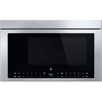
YJMHF930RSS - Microwave Oven JennAir - Free user manual and instructions
Find the device manual for free YJMHF930RSS JennAir in PDF.


User questions about YJMHF930RSS JennAir
0 question about this device. Answer the ones you know or ask your own.
Ask a new question about this device
Download the instructions for your Microwave Oven in PDF format for free! Find your manual YJMHF930RSS - JennAir and take your electronic device back in hand. On this page are published all the documents necessary for the use of your device. YJMHF930RSS by JennAir.
USER MANUAL YJMHF930RSS JennAir
Microwave Oven Safety 2
Internet Connectivity Guide for Connected Appliances Only ....3
FCC Caution....4
General Cleaning....5
INSTALLATION INSTRUCTIONS 7
REQUIREMENTS....7
Tools and Parts 7
Location Requirements 9
Product Dimensions 9
Installation Dimensions 10
Electrical Requirements 10
INSTALLATION 11
Prepare Microwave Oven Hood Combination.... 11
Installation Types 11
Find the Cardboard Plate.... 12
Find the Wall Stud(s) 12
Find the Flush Point.... 13
Mark Upper Cabinet 13
Mark Rear Wall.... 15
Drill holes in Upper Cabinet.... 16
Drill holes in Rear Wall 16
Attach Mounting Plate to Wall 17
Rotate Blower Motor.... 18
Install Damper Assembly 21
Install the Microwave Oven 22
Complete Installation 23
VENTING DESIGN SPECIFICATIONS.... 24
SÉCURITÉ DU FOUR À MICRO-ONDES 26
Your safety and the safety of others are very important.
We have provided many important safety messages in this manual and on your appliance. Always read and obey all safety messages.

This is the safety alert symbol.
This symbol alerts you to potential hazards that can kill or hurt you and others.
All safety messages will follow the safety alert symbol and either the word "DANGER" or "WARNING." These words mean:
DANGER
WARNING
You can be killed or seriously injured if you don't immediately follow instructions.
You can be killed or seriously injured if you don't follow instructions.
All safety messages will tell you what the potential hazard is, tell you how to reduce the chance of injury, and tell you what can happen if the instructions are not followed.
IMPORTANT SAFETY INSTRUCTIONS
When using electrical appliances basic safety precautions should be followed, including the following:
WARNING: To reduce the risk of burns, electric shock, fire, injury to persons, or exposure to excessive microwave energy:
- Read all instructions before using the appliance.
- Read and follow the specific "PRECAUTIONS TO AVOID POSSIBLE EXPOSURE TO EXCESSIVE MICROWAVE ENERGY" found in this manual.
■ This appliance must be grounded. Connect only to properly grounded outlet. See "GROUNDING INSTRUCTIONS" found in this section.
■ Install or locate this appliance only in accordance with the provided Installation Instructions.
■ Some products such as whole eggs and sealed containers - for example, closed glass jars - are able to explode and should not be heated in this oven.
■ Use this appliance only for its intended use as described in the manual. Do not use corrosive chemicals or vapors in this appliance. This type of oven is specifically designed to heat, cook, or dry food. It is not designed for industrial or laboratory use.
■ HOT CONTENTS CAN CAUSE SEVERE BURNS. DO NOT ALLOW CHILDREN TO USE THE MICROWAVE. Use caution when removing hot items.
■ Do not operate this appliance if it has a damaged cord or plug, if it is not working properly, or if it has been damaged or dropped.
■ This appliance should be serviced only by qualified service personnel. Contact nearest authorized service facility for examination, repair, or adjustment.
■ Do not cover or block any openings on the appliance. - Do not store this appliance outdoors. Do not use this product near water – for example, near a kitchen sink, in wet basement, near a swimming pool, or similar locations.
■ Do not immerse cord or plug in water. - Keep cord away from heated surfaces.
■ Do not let cord hang over edge of table or counter.
■ Do not use replacement parts that have not been recommended by the manufacturer (e.g. parts made at home using a 3D printer).
■ See door surface cleaning instructions in the “Microwave Oven Maintenance and Care” section. - Liquids, such as water, coffee, or tea are able to be overheated beyond the boiling point without appearing to be boiling. Visible bubbling or boiling when the container is removed from the microwave oven is not always present. THIS COULD RESULT IN VERY HOT LIQUIDS
- SUDDENLY BOILING OVER WHEN THE CONTAINER IS DISTURBED OR A UTENSIL IS INSERTED INTO THE LIQUID.
■ Do not operate any heating or cooking appliance beneath this appliance.
■ Do not mount unit over or near any portion of a heating or cooking appliance.
■ Do not mount over a sink.
■ Do not store anything directly on top of the appliance used surface when the appliance is in operation.
■ Clean Ventilating Hoods Frequently - Grease should not be allowed to accumulate on hood or filter.
■ When flaming foods under the hood, turn the fan on.
■ Suitable for use above both gas and electric cooking equipment.
■ Intended to be used above ranges with maximum width of 36" (91.44 cm).
■ Do not touch or clean the heating plate after toast cooking, it is very hot.
SAVE THESE INSTRUCTIONS
IMPORTANT SAFETY INSTRUCTIONS
When using electrical appliances basic safety precautions should be followed, including the following:
WARNING: To reduce the risk of burns, electric shock, fire, injury to persons, or exposure to excessive microwave energy:
■ Use care when cleaning the vent-hood filter. Corrosive cleaning agents, such as lye-based oven cleaners, may damage the filter.
■ To reduce the risk of fire in the oven cavity:
- Do not overcook food. Carefully attend appliance when paper, plastic, or other combustible materials are placed inside the oven to facilitate cooking.
- Remove wire twist-ties from paper or plastic bags before placing bag in oven.
- If materials inside the oven ignite, keep oven door closed, turn oven off, and disconnect the power cord, or shut off power at the fuse or circuit breaker panel.
- Do not use the cavity for storage purposes. Do not leave paper products, cooking utensils, or food in the cavity when not in use.
■ Oversized foods or oversized metal utensils should not be inserted in a microwave/toaster oven as they may create a fire or risk of electric shock.
■ Do not clean with metal scouring pads. Pieces can burn off the pad and touch electrical parts involving a risk of electric shock.
■ Do not use paper products when appliance is operated in the toaster mode.
- Do not store any materials, other than manufacturer's recommended accessories, in this oven when not in use.
■ Do not cover racks or any other part of the oven with metal foil. This will cause overheating of the oven.
SAVE THESE INSTRUCTIONS
PRECAUTIONS TO AVOID POSSIBLE EXPOSURE TO EXCESSIVE MICROWAVE ENERGY
(a) Do not attempt to operate this oven with the door open (c) in De not operate the oven if it is damaged. It is particularly open-door operation can result in harmful exposure to important that the oven door close properly and that there is microwave energy. It is important not to defeat or tamper with damage to the: the safety interlocks.
(1) Door (bent).
(b) Do not place any object between the oven front face and (a) Hinges and latches (broken or loosened), door or allow soil or cleaner residue to accumulate on sealing. Door seals and sealing surfaces surfaces.
(d) The oven should not be adjusted or repaired by anyone except properly qualified service personnel.
Internet Connectivity Guide for Connected Appliances Only
IMPORTANT: Proper installation of your appliance prior to use is your responsibility. Be sure to read and follow the installation instructions that came with your appliance.
Connectivity requires Wi-Fi and account creation. App features and functionality are subject to change. Data rates may apply. Once installed, launch the app. You will be guided through the steps to set up a user account and to connect your appliance.
You Will Need:
A home wireless router supporting Wi-Fi, 2.4 Ghz with WPA2 security. If you are unsure of your router's capabilities, refer to the router manufacturer's instructions.
■ The router to be on and have a live internet connection.
■ The 10-character SAID code for your appliance. The SAID code is either printed on a label on the appliance or found on the LCD screen.
Federal Communications Commission (FCC) Compliance Notice
This device complies with Part 15 of the FCC Rules. Operation is subject to the following two conditions:
- This device may not cause harmful interference, and
- This device must accept any interference received, including interference that may cause undesired operation.
Changes or modifications not expressly approved by the party responsible for compliance could void the user's authority to operate the equipment.
Industry Canada (IC) Compliance Notice
This Device complies with Industry Canada License-exempt RSS standard(s). Operation is subject to the following two conditions:
- This device may not cause interference.
- This device must accept any interference, including interference that may cause undesired operation of the device.
Under Industry Canada regulations, this radio transmitter may only operate using an antenna of a type and maximum (or lesser) gain approved for the transmitter by Industry Canada. To reduce potential radio interference to other users, the antenna type and its gain should be so chosen that the equivalent isotropically radiated power (e.i.r.p.) is not more than that necessary for successful communication.
To comply with FCC and Industry Canada RF radiation exposure limits for general population, antenna(s) used for this transmitter must be installed such that a minimum separation distance of 20 cm is maintained between the radiator (antenna) and all persons at all times and must not be co-located or operating in conjunction with any other antenna or transmitter.
If this equipment does cause harmful interference to radio or television reception, which can be determined by turning the equipment off and on, the user is encouraged to try to correct the interference by one of the following measures:
■ Reorient or relocate the receiving antenna.
■ Connect the equipment into an outlet on a circuit different from that to which the receiver is connected.
■ Increase the separation between the equipment and receiver.
■ Consult the dealer or an experienced radio/TV technician for help.
FCC Caution
■ Changes or modifications not expressly approved by Whirlpool Corporation could void the user's authority to operate the equipment.
The antenna(s) used for this transmitter must be installed such that a minimum separation distance of 20 cm is maintained between radiator (antenna) and all persons at all times and must not be co-located or operating in conjunction with any other antenna or transmitter.
Part 15B compliance statements for digital devices:
NOTE: This equipment has been tested and found to comply with the limits for a Class B digital device, pursuant to Part 15 of the FCC Rules. These limits are designed to provide reasonable protection against harmful interference in a residential installation. This equipment generates; uses and can radiate radio frequency energy and, if not installed and used in accordance with the instructions, may cause harmful interference to radio communications. However, there is no guarantee that interference will not occur in a particular installation. If this equipment does cause harmful interference to radio or television reception, which can be determined by turning the equipment off and on, the user is encouraged to try to correct the interference by one of the following measures:
■ Reorient or relocate the receiving antenna.
■ Increase the separation between the equipment and receiver.
■ Connect the equipment into an outlet on a circuit different from that to which the receiver is connected.
■ Consult the dealer or an experienced radio/TV technician for help.
The user manual for the end product must include the following information in a prominent location Instruc
"To comply with FCC RF radiation exposure limits for general population, the antenna(s) used for this transmitter must be installed such that a minimum separation distance of 20 cm is maintained between the radiator (antenna) and all persons at all times and must not be co-located or operating in conjunction with any other antenna or transmitter."
OEM Responsibilities to comply with FCC Regulations
The rebel UI Modules have been certified for integration into products only by OEM integrators under the following conditions:
- The antenna(s) must be installed such that a minimum separation distance 20 cm is maintained between the radiator (antenna) and all persons at all times.
- The transmitter module must not be co-located or operating in conjunction with any other antenna or transmitter.
As long as the two conditions above are met, further transmitter testing will not be required. However, the OEM integrator is still responsible for testing their end-product for any additional compliance requirements required with this module installed (for example, digital device emissions, PC peripheral requirements, etc.)
IMPORTANT: In the event that these conditions cannot be met (for certain configurations or co-location with another transmitter), then the FCC authorizations are no longer considered valid and the FCC ID cannot be used on the final product. in these circumstances, the OEM integrator will be responsible for re-evaluating the end product (including the transmitter) and obtaining a separate FCC authorization.
End Product Labelling
This module is labelled with an FCC ID. If the FCC ID is not visible when the module is installed inside another device, then the outside of the device into which the module is installed must also display a label referring to the enclosed module. In that case, the final end product must be labelled in a visible area or display the following:
"Contains FCC ID: 2AC7Z-RIGEL"
The OEM of this module must only use the approved antenna(s), which have been certified with this module. The OEM integrator has to be aware not to provide information to the end user regarding how to install or remove this RF module or change RF related parameters in the user manual of the end product.
IMPORTANT: Before cleaning, make sure all controls are off and the microwave oven is cool. Always follow label instructions on cleaning products.
Soap, water, and a soft cloth or sponge are suggested first, un otherwise noted.
STAINLESS STEEL AND BLACK STAINLESS STEEL (on some models)
NOTE: To avoid damage to stainless steel surfaces, do not use soap-filled scouring pads, abrasive cleaners, Cooktop Cleaner, steel-wool pads, gritty washcloths, or abrasive paper towels. Damage may occur to stainless steel surfaces, even with one-tim or limited use.
Rub in direction of grain to avoid damaging.
Cleaning Method:
■ Affresh ^®† Stainless Steel Cleaners Part Number W10355016 (not included) or affresh ^®‡ Stainless Steel Cleaning Wipes Part Number W1055049 (not included): See the Quick Start Guide for ordering information.
■ Vinegar for hard water spots.
MICROWAVE OVEN DOOR EXTERIOR
Cleaning Method:
■ Glass cleaner and a soft cloth or sponge: Apply glass cleaner to soft cloth or sponge, not directly on panel.
■ Affresh ^® Kitchen Appliance Cleaners Part Number W10355010 (not included): See “Online Ordering Information” section from Quick Start Guide to order.
NONSTICK CAVITY COATING (on some models)
To avoid damage to the microwave oven cavity, do not use meta or sharp utensils or scrapers or any type of abrasive cleanser or scrubbers.
To avoid damage to the microwave oven cavity, do not use soap-filled scouring pads, abrasive cleaners, steel-wool pads, gritty washcloths, or some paper towels.
On stainless steel models, rub in direction of grain to avoid damaging.
The area where the microwave oven door and frame touch when closed should be kept clean.
Cleaning Method:
Average soil
■ Mild, nonabrasive soaps and detergents:
Rinse with clean water and dry with soft, lint-free cloth.
■ Mild, nonabrasive soaps and detergents: Heat 1 cup (250 mL) of water for 2 to 5 minutes in microwave oven. Steam will soften soil. Rinse with clean water and dry with soft, lint-free cloth.
Heavy soil
Odors
■ Lemon juice or vinegar: Heat 1 cup (250 mL) of water with 1 tbs (15 mL) of either lemon juice or vinegar for 2 to 5 minutes in microwave oven.
GREASE FILTERS
■ Mild cleanser and scouring pad
■ Dishwasher
WIRE RACK
■ Steel-wool pad
■ Dishwasher
TOAST PAN (on some models)
■ Mild cleanser and scouring pad
no Dishwasher
AIR FRY BASKET (on some models)
■ Steel-wool pad
■ Dishwasher
IR SENSOR LENS (on some models)
■ Lens cleaner and lint-free Swab
Clean IR sensor lens when the display shows the cleaning reminder, wait until the product becomes idle and cools down. Or clean when necessary. See "Clean the IR Sensor Lens" section for more details.
EMBEDDED HEATING PLATE (on some models)
■ Glass cleaner and a soft cloth or sponge
There is an embedded heating plate under the oven bottom on some models. After some cooking, the oven bottom glass becomes very hot (see "Online control guide" for more details). Clean the glass after the "Oven too hot" disappeared on the display.
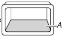
Embedded
Heating Plate
PROBE (on some models)
■ Soap and warm water
The probe is a hand wash only item. Hold onto the rubber end, gently wash with soap and warm water. Rinse and dry well before storing. Place in a provided storage box for easy access. Keep the storage box clean of food and residue. See Quick Start Guide for more information.
Clean The IR Sensor Lens: (on some models)
The IR sensor is located on the right-side of the cavity top. Clean it when the display shows the cleaning reminder or manual clean if necessary.
NOTE: Wait until the product becomes idle and cools down.
To clean the IR sensor lens when reminder appearing:
- Follow the instructions on display to clean.
- Use the lens cleaner and lint-free swab to clean.
- After cleaning, the IR shelter will be closed.
- press CONFIRM/MENU key back to idle.
NOTE: Press BACK key to exit the reminder if you do not clean the lens at the moment, the reminder will appear again in 7 days. Other functions will work as usual, except for the IR sensor cooking function.
To clean the IR sensor lens daily:
If you find the IR sensor cooking function performance is not good, you can clean the IR time.
- Press Settings key and arrow key until Clean and Maintenance submenu.
- Use the arrow key to select IR Cleaning and press CONFIRM/MENU key to select IR cleaning.
- Use the lens cleaner and lint-free swab to clean the lens when the IR shelter is opened.
- After cleaning, the IR shelter will be closed.
- Press CONFIRM/MENU key back to idle.
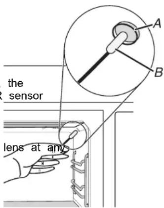
text_image
the sensor lens at anyA. IR Sensor Lens
B. lint-free swab with Lens
Clean/Replace Grease Filter:
The grease filter is on the underside of the microwave oven. Clean monthly.
To clean the grease filter:
Disconnect power.
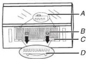
Remove the grease filter by pushing finger grips back and then pull down from the bottom see illustration 1.
Clean the grease filter with a mild cleanser and scouring pad, or clean it with dishwasher.
After cleaning, dry it up, put the grease filter back to the bottom plate, the springs toward pushing finger grips back, until the two tongues are in position, see illustration 2.
To replace a new grease filter:
Disconnect power.
Remove the grease filter by pushing finger grips back and then pull down from the bottom plate, Finger Grips see illustration 1.
Replace a new grease filter by putting the grease filter to the bottom plate, the springs toward back, pushing finger grips back, until the two tongues are in position, see illustration 2.
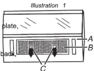
text_image
Illustration 1 plate, back, A B CA. Bottom Plate
B. Grease Filter
CpIaFinger Grips
Replacing Charcoal Filter:
The charcoal filter is behind the grease filter. It cannot be cleaned and should be replaced every 6 months, while the display shows the filter alert “Change the Charcoal Filter and reset reminder in Settings”.
To replace the charcoal filter:
Disconnect power.
Remove the grease filter by pushing finger grips back and then pull down from the bottom set aside, see illustration 1.
Remove the charcoal filter out of the bottom plate by pulling the four hooks out, see illustra. Replace the old charcoal filter with a new charcoal filter.
Put the charcoal filter back to the bottom plate, insert the four hooks into the bottom plate. Put the grease filter back into the bottom plate and the springs toward the back. Push the grips back, until the two tongues are in position, see illustration 2.
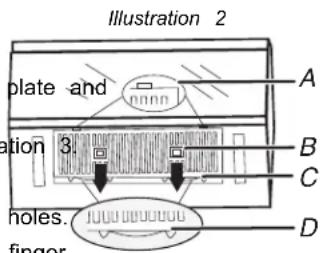
text_image
Illustration 2 plate and 3. holes. finger A B C DA. Tongues
B. Finger
Grip
C. Grease
Filter
D. Spring
To remove the filter alert and reset filters duration:
After replacing the charcoal filter, to remove the filter alert on the display, retrieve another duration.
Press Setting key, use Arrow key to select Cleaning and Maintenance submenu, press CONFIRM/MENU key to enter.
Use Arrow key to select Reset filter submenu, press CONFIRM/MENU key to reset.
The charcoal filter retrieves another 6 months duration now.
NOTE: For roof venting and wall venting, the charcoal filter is not necessary, but the filter alert will still appear every 6 months. You can follow the above steps to remove the alert.

text_image
Illustration 3 months A B C DA. Holes
B. Hooks
C. Charcoal
Filter
D. Bottom
Plate
INSTALLATION INSTRUCTIONS REQUIREMENTS
Tools and Parts
Tools Needed
■ Measuring tape
■ Pencil
■ Scissors
■ Masking tape or thumbtacks
Drill
■ No. 2 Phillips screwdriver
■ Stud finder
■ No. 3 Phillips screwdriver for 1/4-20 x 3" (76 mm) bolts
■ 3/16" (5 mm), 3/8" (10 mm), 5/8" (16 mm) drill bits
■ 3/4" (19 mm) hole saw
■ Keyhole saw
■ Diagonal wire cutting pliers
■ 7/16" (11 mm) socket wrench (or box wrench) for 1/4" x 2" (6.4 mm x 51 mm) lag screws
■ 1 1/2" (38 mm) diameter hole drill bit for wood or metal cabinet
■ Caulking gun and weatherproof caulking compound
■ Duct tape.
Materials Needed
■ Standard fittings for wall or roof venting. See the "Venting Design Specifications" section.
Parts Supplied
| Part Drawing Description | Qty Where can find? | |||
| Screw Pack | 3/16-24 x 3" round-head bolts | 2 | 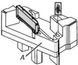 A. Inner Form in the cavity A. Inner Form in the cavity | |
| 1/4-20 x 3" flat-head bolts | 2 | |||
| Washers 2 | ||||
| 3/16" toggle nuts 2 | ||||
| 1/4" x 2" lag screws 2 | ||||
| #6 x 3/8" Sheet metal screws | 2 | |||
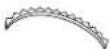 | Power supply cord bushing | 1 | ||
| Damper | Damper for wall or roof venting | 1 | ||
| Spacer | 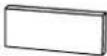 | Spacer(L*W*T: 40*10*1.6 mm) | 8 | B. Inside the Literature pack |
C
C. Outer Form in the Carton
Literature Pack Literature 1
Mounting Pate
Mounting plate 1
Check local codes. Check existing electrical supply. See "Electrical Requirements".
It is recommended that all electrical connections be made by a licensed, qualified electrical installer.
NOTE:
The hardware items listed here are for wood studs. For other types of wall structures, be sure to use appropriate fasteners.
Be sure to purchase only Whirlpool factory-certified parts and accessories for your appliance. Your installation may require additional parts. To order, see the "Online Ordering Information" section of the Quick Start Guide.
Location Requirements
Product Dimensions
Check the opening where the microwave oven will be installed. The location must provide:
◆ Minimum installation dimensions. See the “Installation Dimensions” illustration.
Minimum one 2" x 4" (5.1 x 10.2 cm) wood wall stud and minimum 3/8" (1 cm) thickness drywall or plaster/lath within cabinet opening.
◆ Support for weight of 150 lbs (68 kg) which includes microwave oven and items placed inside the microwave oven and upper cabinet.
◆ Grounded electrical outlet inside upper cabinet. See the "Electrical Requirements" section.
NOTE:
Some models have a pocket handle. If installing the microwave near a right side wall, make sure there is at least 3" (7.6 cm) of clearance between wall and microwave oven so you can grab the handle integrated inside the door.
Some cabinet and building materials are not designed to withstand the heat produced by the microwave oven for cooking. Check with your builder or cabinet supplier to make sure that the materials used will not discolor, delaminate, or sustain other damages.
Special Requirements
For Wall Venting Installation Only:
◆ Cutout must be free of any obstructions so that the vent fit properly and the damper blade opens freely and fully.
For Roof Venting Installation Only:
If you are using a rectangular-to-round transition piece, the 3" (7.6 cm) clearance needs to exist above the microwave oven so that the damper blade can open freely and fully. See "Rectangular to Round Transition" illustration in the "Venting Design Specifications" section.
A. 2918 " (76.1 cm)
B. 1718 (45.4 cm)
C. 12/8" (31.3 cm)
Installation Dimensions
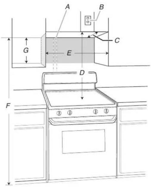
NOTE: The grounded 3 prong outlet must be inside the upper cabinet. See the "Electrical Requirements" section.
text_image
A B C G E D FA. 2" x 4" (5.1 cm x 10.2 cm) E. 30" (76.2 cm) minimum wall stud F. 72" (182.8 cm) recomm
B. Grounded 3 prong outlet
C. Upper cabinet depth (with door)***
D. 36" (91.4 cm) recommended*
30" (76.2 cm) typical**
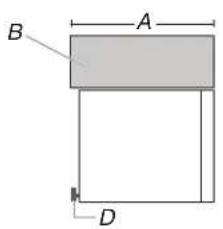
text_image
B A D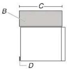
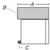
text_image
B C DA. (Flush) 12 ^3/4 " to 13" (32.3 cm to 33 cm) deep
B. Cabinet
C. Less than 124" (32.3 cm) deep
D. Mounting plate
Exact dimensions may vary depending on type of range/cooktop below.
*36" (91.4 cm) is recommended for 72" (182.8 cm) installation height.
**30" (76.2 cm) is typical for 66" (167.6 cm) installation height.
***Measure from the back wall to where the front bottom surface of the microwave oven needs to be (Dimension A).
For 12" (30.5 cm) to 12 ^3/4 " (32 cm) cabinets, the microwave oven will protrude from the cabinet.
For 12 ^3/4 " (32 cm) to 13" (33 cm) cabinets, the microwave oven is flush to the cabinet.
NOTE: It may be necessary to use a number of spacers, between the mounting plate and the wall, to achieve a more 'Flush' appearance. See "Attach Mounting Plate to Wall" section for more details.
If cabinets are deeper than 13" (33 cm), and up to 16" (40.6 cm), use the bump out mounting kit, replacing the mounting plate supplied with the product. The bump out mounting kit (part#- W11630300) is not provided.
A. (Bump out) 13" to 16"
(33 cm to 40.6 cm) deep
B. Cabinet
C. Bump out mounting bracket
To order, see the "Online Ordering Information" section of the Quick Start Guide.
For cabinets with other dimension's, we suggest selecting other Whirlpool Products.
Electrical Requirements
WARNING

Electrical Shock Hazard
Plug into a grounded 3 prong outlet.
Do not remove ground prong.
Do not use an adapter.
Do not use an extension cord.
Failure to follow these instructions can result in death, fire, or electrical shock.
Observe all governing codes and ordinances.
Required:
■ A 120 V, 60 Hz, AC only, 15 A or 20 A electrical supply with a fuse or circuit breaker.
Recommended:
■ A time-delay fuse or time-delay circuit breaker.
■ A separate circuit serving only this microwave oven.
GROUNDING INSTRUCTIONS
For a grounded, cord-connected appliance:
This appliance must be grounded. In the event of a malfunction or breakdown, grounding will reduce the risk of electric shock by providing a path of least resistance for electric current. This appliance is equipped with a cord have an equipment-grounding conductor and a grounding plug. The plug must be plugged into an appropriate outlet that is properly installed and grounded in accordance with all local codes and ordinances.
WARNING: Improper connection of the equipment-grounding conductor can result in a risk of electric shock. Check with a qualified electrician or serviceman if you are doubt as to whether the appliance is properly grounded. not modify the plug provided with the appliance: if it will the outlet, have a proper outlet installed by a qualified electrician.
SAVE THESE INSTRUCTIONS
This device complies with Industry Canada ICES-001.
INSTALLATION
Prepare Microwave Oven Hood Combination
WARNING
Excessive Weight Hazard
Use two or more people to move and install or uninstall appliance.
Failure to do so can result in back or other injury.
e in
Do 1. To avoid possible damage to the work surface, cover the work not fit surface.
2. Remove cardboard plate from the outer foam in the carton. It is for upper-cabinet and wall installation.
3. Remove the screw pack from the inner foam in the cavity.
4. Remove the damper from the inner foam in the cavity.
5. Remove the literature pack from the outer foam in the carton.
6. Remove shipping materials, tape and film from microwave.
7. Remove the mounting plate from the outer foam in the cavity.
8. Tape the microwave oven door closed so that the door does not swing open while the microwave oven is being handled.
NOTE: To avoid damage to the microwave oven, do not grip or use the door or door handle while the microwave oven is being handled.
Installation Types
This microwave oven is designed for adaptation to the following three types of ventilation, choose one type before installation. NOTE: For roof venting and wall venting, charcoal filter is not necessary, uninstall the charcoal filter before use. See the "Complete Installation" section for details.
Recirculation
(Factory Default Setting)
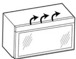
natural_image
Simple line drawing of a rectangular box with three curved arrows on top (no text or symbols)Wall Venting Roof Venting
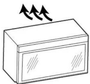
natural_image
Simple line drawing of a rectangular box with two upward arrows above it (no text or symbols)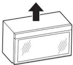
natural_image
Simple line drawing of a rectangular box with an upward arrow on top (no text or symbols)Find the Cardboard Plate
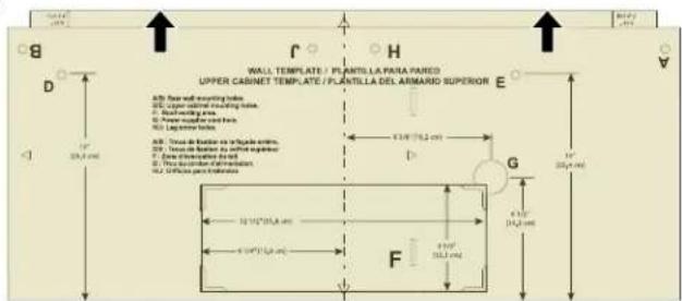
The cardboard plate is used as wall template and upper-cabinet template. It is located on the outer foam in the carton. Find it before installation.
text_image
WALL TEMPLATE / PLANTILLA PARA PARED UPPER CABINET TEMPLATE / PLANTILLA DEL ARMARIO SUPERIOR A3: Rear wall mounting holes. B4: Upper nominal mounting holes. C5: Wall mounting area. D6: Power output screw holes. E7: Linger tooth. A8: Rear de Balle de la plane wheel. B9: Rear de Balle de la plane wheel. C10: Rear de Balle de la plane wheel. D11: Rear de Balle de la plane wheel. E12: Rear de Balle de la plane wheel. F13: Rear de Balle de la plane wheel. G14: Rear de Balle de la plane wheel. H15: Rear de Balle de la plane wheel. F16: Rear de Balle de la plane wheel. G17: Rear de Balle de la plane wheel. H18: Rear de Balle de la plane wheel. F19: Rear de Balle de la plane wheel. G20: Rear de Balle de la plane wheel. F21: Rear de Balle de la plane wheel. G22: Rear de Balle de la plane wheel. F23: Rear de Balle de la plane wheel. G24: Rear de Balle de la plane wheel. F25: Rear de Balle de la plane wheel. G26: Rear de Balle de la plane wheel. F27: Rear de Balle de la plane wheel. G28: Rear de Balle de la plane wheel. F29: Rear de Balle de la plane wheel. G30: Rear de Balle de la plane wheel. F31: Rear de Balle de la plane wheel. G32: Rear de Balle de la plane wheel. F33: Rear de Balle de la plane wheel. G34: Rear de Balle de la plane wheel. F35: Rear de Balle de la plane wheel. G36: Rear de Balle de la plane wheel. F37: Rear de Balle de la plane wheel. G38: Rear de Balle de la plane wheel. F39: Rear de Balle de la plane wheel. G40: Rear de Balle de la plane wheel. F41: Rear de Balle de la plane wheel. G42: Rear de Balle de la plane wheel. F43: Rear de Balle de la plane wheel. G44: Rear de Balle de la plane wheel. F45: Rear de Balle de la plane wheel. G46: Rear de Balle de la plane wheel. F47: Rear de Balle de la plane wheel. G48: Rear de Balle de la plane wheel. F49: Rear de Balle de la plane wheel. G50: Rear de Balle de la plane wheel. F51: Rear de Balle de la plane wheel. G52: Rear de Balle de la plane wheel. F53: Rear de Balle de la plane wheel. G54: Rear de Balle de la plane wheel. F55: Rear de Balle de la plane wheel. G56: Rear de Balle de la plane wheel. F57: Rear de Balle de la plane wheel. G58: Rear de Balle de la plane wheel. F59: Rear de Balle de la plane wheel. G60: Rear de Balle de la plane wheel. F61: Rear de Balle de la plane wheel. G62: Rear de Balle de la plane wheel. F63: Rear de Balle de la plane wheel. G64: Rear de Balle de la plane wheel. F65: Rear de Balle de la plane wheel. G66: Rear de Balle de la plane wheel. F67: Rear de Balle de la plane wheel. G68: Rear de Balle de la plane wheel. F69: Rear de Balle de la plane wheel. G70: Rear de Balle de la plane wheel. F71: Rear de Balle de la plane wheel. G72: Rear de Balle de la plane wheel. F73: Rear de Balle de la plane wheel. G74: Rear de Balle de la plane wheel. F75: Rear de Balle de la plane wheel. G76: Rear de Balle de la plane wheel. F77: Rear de Balle de la plane wheel. G78: Rear de Balle de la plane wheel. F79: Rear de Balle de la plane wheel. G80: Rear de Balle de la plane wheel. F81: Rear de Balle de la plane wheel. G82: Rear de Balle de la plane wheel. F83: Rear de Balle de la plane wheel. G84: Rear de Balle de la plane wheel. F85: Rear de Balle de la plane wheel. G86: Rear de Balle de la plane wheel. F87: Rear de Balle de la plane wheel. G88: Rear de Balle de la plane wheel. F90: Rear de Balle de la plane wheel. G91: Rear de Balle de la plane wheel. F92: Rear de Balle de la plane wheel. G93: Rear de Balle de la plane wheel. F94: Rear de Balle de la plane wheel. G95: Rear de Balle de la plane wheel. F96: Rear de Balle de la plane wheel. G97: Rear deses et leses et leses et leses et leses et leses et leses et leses et leses et leses et leses et leses et leses et leses et leses et leses et leses et leses et leses et leses et leses et leses et leses et leses et leses et leses et leses et leses et leses et leses et leses et leses et leses et leses et less et leses et les sats et les sats et les sats et les sats et les sats et les sats et les sats et les sats et les sats et les sats et les sats et les sats et les sats et les sats et les sats et les sats et les sats et les sats et les sats et les sats et les sats et les sats et les sats et les sats et les sats et les sars et les sars et les sars et les sars et les sars et les sars et les sars et les sars et les sars et les sars et les sars et les sars et les sars et les sars et les sars et les sars et les sars et les sars et les sars et les sars et les sars et les sars et les sars et les sars et les sars and their sides and their sides and their sides and their sides and their sides and their sides and their sides and their sides and their sides and their sides and their sides and their sides and their sides and their sides and their sides and their sides and their sides and their sides and their sides and their sides and their sides and their sides and their sides and their sides and their sides and their sides and their sides and their sides and their sides and their sides and their sides and their sides and their sides and their sides, respectively. F100' (201.4 m)Find the Wall Stud(s)
NOTE: If no wall studs exist within the cabinet opening, do not install the microwave oven.
See illustrations in "Possible Wall Stud Configurations."
- Using a stud finder, locate the edges of the wall stud(s) within the opening.
- Mark the center of each stud, and draw a plumb line down each stud center. See illustrations in "Possible Wall Stud Configurations."
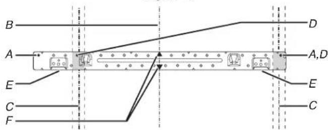
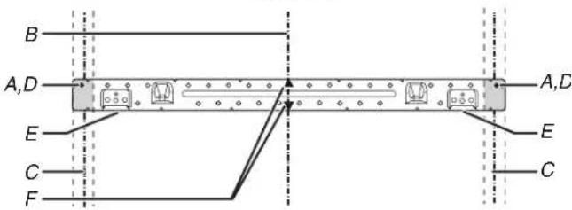
Possible Wall Stud Configurations
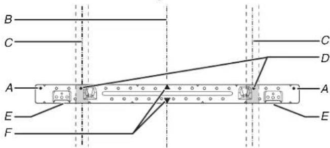
These depictions show examples of preferred installation configurations with the mounting plate.
No Wall Studs at End Holes
Figure 1
text_image
B C A E F C D A EA. End holes (on mounting plate)
B. Cabinet opening vertical centerline
C. Wall stud centerlines
D. Holes for lag screws
E. Support tabs
F. Mounting plate center markers
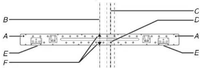
No Wall Studs at End Holes
Figure 2
text_image
B A E F C D A ENOTE: If wall stud is within 6" (15.2 cm) of the vertical centerline (see the "Mark Rear Wall" section), only recirculation or roof venting installation can be done.
A. End holes (on mounting plate)
B. Cabinet opening vertical centerline
C. Wall stud centerlines
D. Holes for lag screws
E. Support tabs
F. Mounting plate center markers
Wall Stud at End Holes
Figure 3
text_image
B A E C F D A,D E CA. End holes (on mounting plate)
B. Cabinet opening vertical centerline
C. Wall stud centerlines
D. Holes for lag screws
E. Support tabs
F. Mounting plate center markers
Wall Stud at End Holes
Figure 4
text_image
B A,D E C F A,D E CA. End holes (on mounting plate)
B. Cabinet opening vertical centerline
C. Wall stud centerlines
D. Holes for lag screws
E. Support tabs
F. Mounting plate center markers
Find the Flush Point
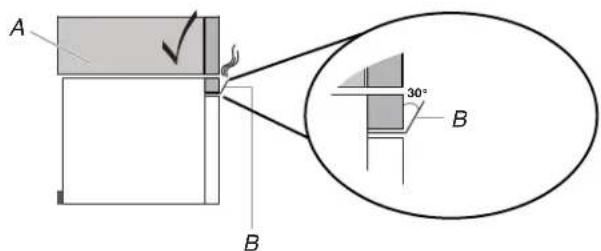
This product is designed to be flush with the cabinet, and the flush point should be found before installation. Don't install with the front of the microwave oven located behind the front of the cabinet/door.
Flush to Cabinet door Flush to Cabinet door Don't install with the front of Don't install with the front the microwave oven located of the microwave oven behind the front of the located behind the front of cabinet/door. the cabinet/door.
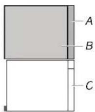
text_image
A B CA. Cabinet door
B. Cabinet
C. Microwave oven door
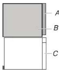
text_image
A B CA. Cabinet door
B. Cabinet
C. Microwave oven door
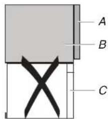
text_image
A B CA. Cabinet door
B. Cabinet
C. Microwave oven door
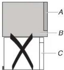
text_image
A B CA. Cabinet door
B. Cabinet
C. Microwave oven door
NOTE: The grille baffle will automatically open 30° when the microwave oven uses the ventilation and cooking function. Do not install the microwave oven with the grille baffle behind the front of the cabinet/door otherwise it will block the air outlet.
- Using a tape, measure clearly and mark the vertical centerline of the opening. Make sure it aligns with the vertical wall centerline.
text_image
A BA. Upper Cabinet Centerline
B. Wall Centerline
NOTE: The cardboard plate is fit for depth of 12" to 13" (30.5 cm to 33.02 cm) cabinet installation, but need some adjustment for different depths. See the following steps 2, 3. If cabinets are deeper than 13" (33 cm), and up to 16" (40.6 cm), use the bump out mounting kit, replacing the mounting plate supplied with the product. The bump out mounting kit (part#- W11630300) is not provided.
If your cabinet is 12" 3/4" 1(30.5 cm to 32.4 cm) depth, follow the step 2:
Place the cardboard plate against the bottom of the upper cabinet.
NOTES:
■ Make sure the back edge of the cardboard plate aligns with the wall and back edge of upper cabinet.
■ Make sure the center marks on the cardboard plate align with the upper cabinet centerline which draw in step 1.
■ Make sure the arrow on the cardboard plate are facing out.
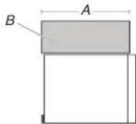
A. Less than 12" (30.5 cm) deep
B. Cabinet
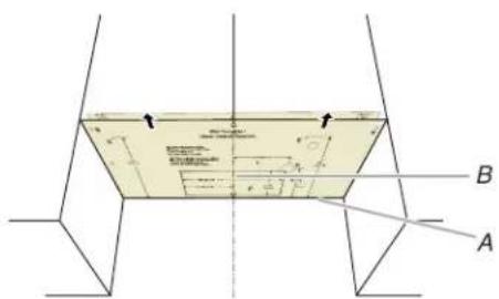
text_image
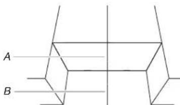
Technical diagram showing a 3D geometric structure with labeled points A and B, and annotations for dimensions and angles.B. Upper Cabinet Centerline and Center Marks on Cardboard Plate
Flush to cabinet door
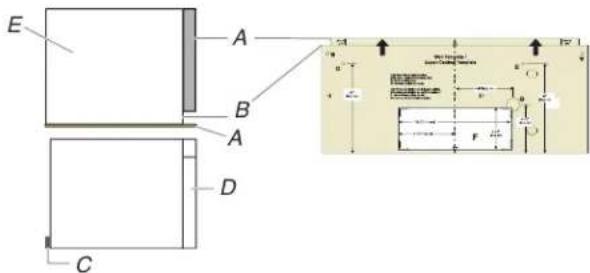
text_image
E A B A D C C1 C2 F F1A. Front Edge of Cardboard Plate and Upper Cabinet Door
B. Upper Cabinet and Cardboard Plate 0.75" (1.9 cm) Line
C. Mounting plate
D. Microwave oven door
E. Cabinet
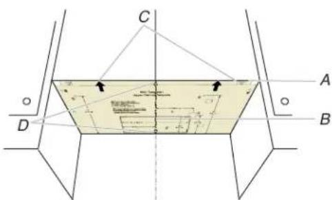
If your cabinet depth is 4"12 to 13" (32.4 cm to 33 cm) depth:
- Place the cardboard plate against the bottom of the upper cabinet.
NOTES:
■ Make sure the front edge of the cardboard plate align with the front edge of upper cabinet.
■ Make sure the center marks on the cardboard plate align with the upper cabinet centerline which draw in step 1.
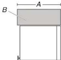
text_image
A BA. (Flush) 12 34 " to 13" (32.4 cm to 33 cm) deep B. Cabinet
text_image
C A D BA. Front Edge of Cardboard Plate and Front Edge of Upper Cabinet
B. Upper Cabinet Centerline
C. Arrows on Cardboard Plate
D. Center Marks on Cardboard Plate
NOTE: If the upper cabinet doors protrude from the upper cabinet, the cardboard can be adjusted outward to be flush with the upper cabinet door.
For example the upper cabinet door is 0.75" (1.9 cm) thick, you can align the cardboard plate 0.75" (1.9 cm) line with the upper cabinet.
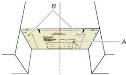
- Use a pencil to mark the power cord hole and two mounting nut holes.
text_image
B AA. Power Cord Hole B. Mounting Nut Holes
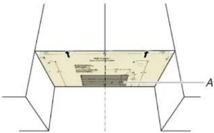
- Use a pencil to mark the upper cabinet vent hole. This step can be skipped if your unit is using recirculation or wall venting installation.
text_image
Technical diagram showing a cross-sectional view of a structural component with labeled dimensions and reference points.A. Upper Cabinet Hole
Mark Rear Wall
The microwave oven must be installed on a minimum of 1 wall stud, preferably 2, using a minimum of 1 lag screw, preferably 2. See "Find the Wall Stud(s)" section for find the wall studs.
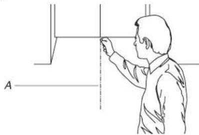
- Use a pencil to mark the power cord hole and two mounting nut holes.
natural_image
Line drawing of a person pointing at a vertical line with labeled point A (no text or symbols beyond label)A. Centerline
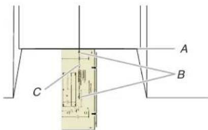
- Hold the cardboard plate on the rear wall while aligning the side center marks (B) on the cardboard plate with the vertical centerline draw in step 1. Make sure the cardboard plate is level, and that the top of the cardboard template is butted up against the bottom edge of the upper cabinet.
text_image
A B CA. Bottom Edge of Upper Cabinet and Top of the Cardboard Plate
B. Side Center Marks on Cardboard Plate
C. Centerline
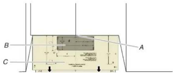
- Align the center markers on the cardboard plate, to the centerline on the wall, making sure it is level, and that the 40 of the cardboard template is butted up against the back edge of the upper cabinet. (see following NOTE before making marks).
Use a pencil to mark the wall venting hole (wall venting installation only), skip it if your unit is for recirculation or upper cabinet venting installation.
text_image
B C A 200 100 50 40 30 20 10 0 -5 -10 -15 -20A. Back Edge of Upper Cabinet
B. Wall Venting Hole
C. Cardboard Plate
text_image
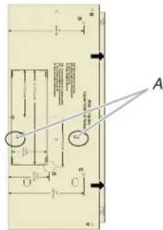
Technical diagram with labeled components and directional arrows, likely from an engineering or mechanical drawing.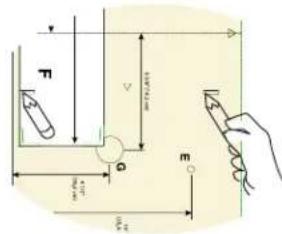
text_image
Technical diagram showing a hand holding a pencil, with labeled dimensions and force vectors for physics or engineering analysis.A. Cardboard Plate Bottom Position Line
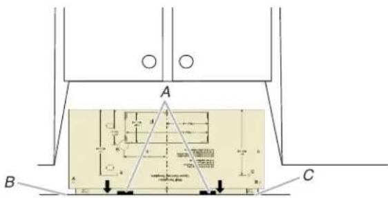
- Using the bottom edge of the cardboard plate, align it with the two small lines (A), and draw a line (B) indicating where the bottom edge of the mounting plate (C) should be.
NOTE:
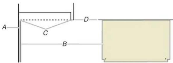
■ If the front edge of the upper cabinet is lower than the back edge, lower the cardboard template so that its top is level with the front edge of the cabinet.
text_image
A C D BA. Rear wall
B. Cardboard plate
C. Top of cardboard plate must align with front edge of cabinet
D. Front edge of upper cabinet
text_image
A B CA. Two Small Lines
B. Cardboard Plate Bottom Line
C. Bottom Edge of Mounting Plate
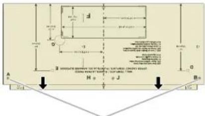
- Draw A and B two small circles, H and J is not necessary, depending on your need.
text_image
A B H J D B D 3. SURFACE SHEET TO THE VENTURE CULTURE (FROVE ROOT) 200 NASH FLOWER 150 NASH FORUM 400 NASH FORUM 150 NASH FORUM 400 NASH FORUM 150 NASH FORUM 400 NASH FORUM 150 NASH FORUM 400 NASH FORUM 150 NASH FORUM 400 NASH FORUM 150 NASH FORUM 400 NASH FORUM 150 NASH FORUM 400 NASH FORUM 15 400 NASH FORUM 15 400 NASH FORUM 15 400 NASH FORUM 15 400 NASH FORUM 15 400 NASH FORUM 15 400 NASH FORUM 15 400 NASH FORUM 15 400 NASH FORUM 15 400 NASH FORUM 15A and B holes
Drill holes in Upper Cabinet
-
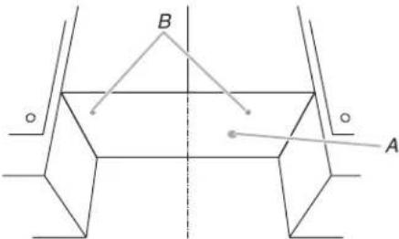
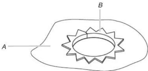
Using a drill and the 0.75" (1.9 cm) hole saw, cut out the power cord hole (A).
-
Drill two mounting nut holes (B), which are 3/8" (10 mm) holes at points "D" and "E" on the cardboard template. These are for two 1/4-20 x 3" bolts and washers used to secure the microwave oven to the upper cabinet.
text_image
B AA. Power Cord Hole
B. Mounting Nut Holes
NOTE: If upper cabinet is metal, the supply cord bushing needs to be installed around the supply cord hole as shown.
text_image
A BA. Metal cabinet
B. Power supply cord bushing
- Using a keyhole saw, cut out the rectangular roof venting cutout area. Skip this step if for recirculation venting or wall venting installation.
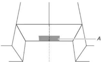
natural_image
Pure geometric diagram of a symmetrical 3D shape with no text, numbers, or symbolsA. Roof Venting Cutout Area
Drill holes in Rear Wall
- The mounting plate is located inside the outer foam in the cavity, take it out.
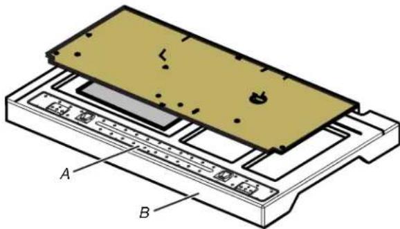
natural_image
3D diagram of a device with labeled components A and B, showing layered structure without any text or symbols.A. Mounting Plate
B. Outer Foam in the Carton
- Attach the mounting plate to wall. Make sure the 2 holes on mounting plate align with the A and B holes marked in the "Mark Rear wall" section and the mounting plate center markers align with the Center Mark.
NOTE: It may be necessary to use a number of the spacers, between the mounting plate and the wall, to achieve a more 'Flush' appearance. See "Attach Mounting Plate to Wall" section for more details.
Measure from the back wall to where the front bottom surface of the microwave oven needs to determine the number of spacers needed.
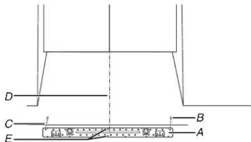
text_image
D C E A BA. Mounting Plate
B. A and B holes
C. Mounting Plate Bottom Line
D. Center Mark
E. Mounting plate center markers
- Drill holes at A and B, if the Wall studs are not located A hole, do not drill A and B hole, and follow the below instruction.
In addition to being installed on at least 1 wall stud, the mounting plate must attach to the wall at both end holes. If end holes are not over wall studs, use two 3/16-24 x 3" round-head bolts with toggle nuts; if 1 end hole is over a wall stud use 1 lag screw and one 3/16-24 x 3" round-head bolt with toggle nut; or if both end holes are over wall studs, use 2 screws. Following are 3 installation configurations.
Installation for No Wall Studs at End Holes
(Figures 1 and 2 in Find the Wall Stud(s) section)
- Drill 5/8" (1.6 cm) holes through the wall at both end holes marked in Step 3 of the "Mark Rear Wall."
- Drill 3/16" (5 mm) hole(s) into the wall stud(s) at the hole(s) marked in step 6 of the "Mark Rear Wall." Refer to figures 1 and 2 in "Possible Wall Stud Configurations" in the "Locate Wall Studs(s)" section.
Installation for Wall Stud at One End Hole (Figure 3 in Find the Wall Stud(s) section)
- Drill a 3/16" (5 mm) hole into the wall stud at the end hole marked in Step 3 of the "Mark Rear Wall."
- If installing on a second wall stud, drill a 3/16" (5 mm) hole into the wall stud at the other hole marked in Step 6 of the "Mark Rear Wall." Refer to Figure 3 in "Possible Wall Stud Configurations" in the "Locate all Stud(s)" section.
- Drill a 5/8" (1.6 cm) hole through the wall at the other end,
Installation for Wall Studs at Both End Holes (Figure 4 in Find the Wall Stud(s) section)
-
Drill 3/16" (5 mm) holes into the studs at the end holes marked in Step 3 of the "Mark Rear Wall."
-
Using a keyhole saw, cut out the rectangular wall venting cutout area. Skip this step if for recirculation venting or roof venting installation.
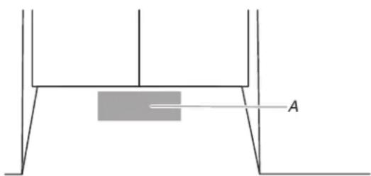
text_image
AA. Wall Venting Cutout Area
Attach Mounting Plate to Wall
- Position mounting plate on the wall.
NOTE: It may be necessary to use a number of the spacers, between the mounting plate and the wall, to achieve a more Flush' appearance. Stick spacers before position mounting plate on the wall.
Measure from the back wall to where the front bottom surface of the microwave oven needs to be to determine the number of spacers needed.
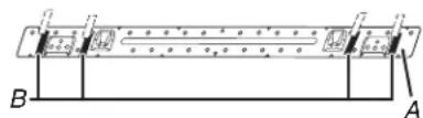
text_image
B AA. Mounting Plate
B. 1/16" (1.6 mm) thickness
| Depth of cabinet Mounting plate | |
| 12" to 13"(30.5 cm to 33 cm) | Mounting plate |
| 13^1/_16" (33.2 cm) Mounting plate + 4 pieces of spacer | |
| 13^1/_8" (33.3 cm) Mounting plate + 8 pieces of spacer | |
- Secure the mounting plate to the wall at both end holes drilled into the wall studs and/or drywall using either 3/16-24 x 3" round-head bolts and toggle nuts or 1/4 x 2" lag screws.
Refer to illustrations in “Possible Wall Stud Configurations” in the “Locate Wall Stud(s)” section, and the following sections “No Wall Studs at End Holes (Figures 1 and 2 in Find the Wa Stud(s) section)” or “Wall Stud at One End Hole (Figure 3 in Find the wall Stud(s) section)”.
- Insert lag screws into both end holes.
- Check alignment of mounting plate, making sure it is level.
- Secure the two end hole screws.
No Wall Studs at End Holes (Figures 1 and 2 in Find the Wall Stud(s) section)
NOTE: The mounting plate must be secured to the wall on at least 1 wall stud as well as at both ends.
- With the support tabs of the mounting plate facing forward, insert 3/16-24 x 3" round-head bolts through both end holes of mounting plate.
- Start toggle nuts on bolts from the back of the mounting plate. Leave enough space for the toggle nuts to go through the wall and to open.
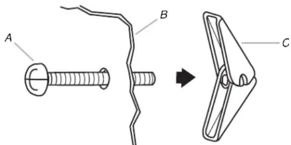
text_image
A B CA. 3/16-24 x 3" round-head bolt
B. Mounting plate
C. Spring toggle nut
-
Position mounting plate on the wall.
-
Push the 2 bolts with toggle nuts through the drywall, and finger tighten the bolts to make sure toggle nuts have open against drywall.
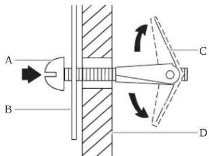
text_image
A B C DA. 3/16-24 x 3" round-head bolt
B. Mounting plate
C. Spring toggle nut
D. Drywall
- Insert lag screw(s) into the hole(s) drilled into wall stud(s) in Step 2 of "Installation for No Wall Studs at End Holes" in the "Drill Holes in Rear Wall" section.
- Check alignment of mounting plate, making sure it is level.
- Securely tighten all lag screws and bolts.
Wall Stud at One End Hole (Figure 3 in Find the Wall Stud(s) section)
- With the support tabs of the mounting plate facing forward, insert a 3/16-24 x 3" round-head bolt through the end hole that fits over the 5/8" (16 mm) hole drilled in step 3 of "Installation for Wall Stud at One End Hole" in the "Drill Holes in Rear Wall" section.
- Start a toggle nut on the bolt from the back of the mounting plate. Leave enough space for the toggle nut to go through the wall and to open.
- Position mounting plate on the wall.
- Push the bolt with toggle nut through the drywall, and finger tighten the bolt to make sure toggle nut has opened against drywall.
- Insert a lag screw into the remaining end hole.
- If installing on a second wall stud, insert a lag screw into the other hole drilled in Step 2 of "Installation for Wall Stud at One End Hole" in the "Drill Holes in Rear Wall" section.
- Check alignment of mounting plate, making sure it is level.
- Securely tighten the lag screw(s) and bolt.
Rotate Blower Motor
This section include wall and roof venting installation, both venting installation need rotate blower motor, select one ventilation type before install the microwave oven. And follow the propriated instruction to rotate the blower motor. If for recirculation installation, no need to rotate the blower motor, this section can be skip.
Rotate Blower Motor for Wall Venting Installation
- Remove screws attaching damper plate to back of microwave oven, set the screws aside.
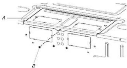
text_image
Technical diagram of a vehicle interior with labeled components A and B, showing structural layout and alignment indicators.A. Damper plate
B. Screw
- Turn and hold the damper plate vertically as shown.
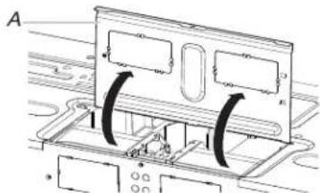
text_image
AA. Damper plate
- Remove 2 blower screws attaching blower motor to the microwave oven, and set aside.
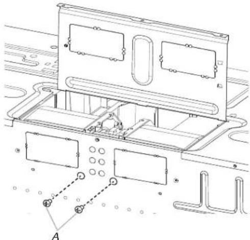
natural_image
Technical line drawing of a mechanical assembly with no visible text or symbolsA. Blower screws
- Disconnect the blower motor wire from the connector.
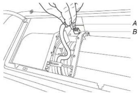
text_image
Technical diagram showing a hand connecting components labeled A and B to a mechanical or electrical component.A. Blower motor wire
B. Connector
- Lift blower motor out of microwave oven, and set aside.
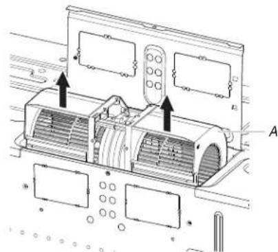
text_image
Technical diagram of a car air conditioner unit with labeled components and airflow arrowsA. Blower motor
- Using diagonal wire cutting pliers, gently snip out the rectangular damper vent covers at the perforations.
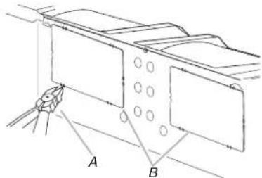
text_image
Technical diagram showing labeled components A and B with circular features and a connecting rod, likely illustrating a mechanical or electrical assembly.A. Diagonal wire cutting pliers
B. Rectangular damper vent cover
- Hold the blower motor wire, put the wire through the blower motor bridge.
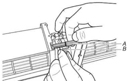
text_image
Technical diagram showing hands operating a mechanical component with labeled parts A and BA. Blower motor bridge
B. Blower motor wire
- Lower blower motor back into the microwave oven. Exhaust ports face the back of the microwave oven.
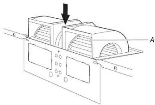
natural_image
Technical line drawing of a mechanical component with mounting holes and a downward arrow indicating force or direction (no text or symbols)A. Exhaust Port
- Reconnect the blower motor wire into the connector.

text_image
Technical diagram showing a hand connecting components labeled A and B to a mechanical or electrical component, with visible wiring and mounting brackets.A. Blower motor wire
B. Connector
- Reattach the 2 blower screws into the recessed holes in the back of the microwave.
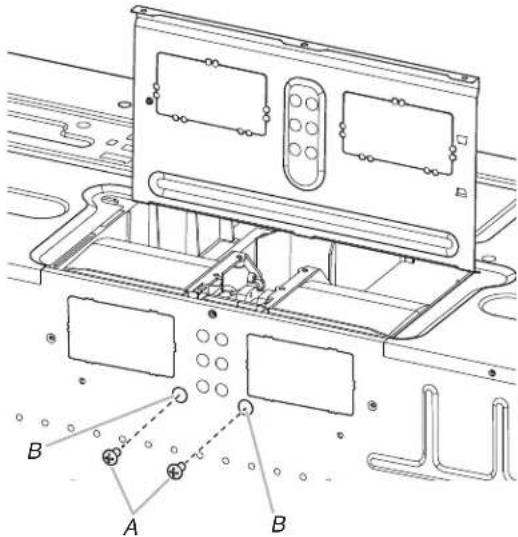
text_image
Technical diagram of an electronic device with labeled components A and B, showing internal wiring and mounting brackets.A. Screws
B. Holes
- Check to make sure the 2 screws are secured properly in blower motor screw holes, so that the motor cannot move.
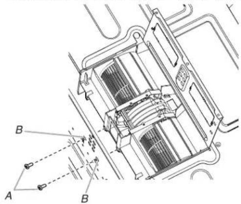
text_image
Technical diagram of a vehicle air intake system with labeled components A and B, showing internal airflow paths and structural details.A. Screws
B. Blower motor screw holes
- Return the damper plate to its original horizontal position.
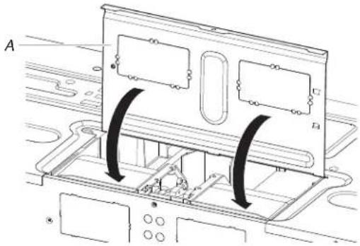
natural_image
Diagram of a computer monitor with two panels and directional arrows indicating movement or force (no text or symbols present)A. Damper plate
- Secure damper plate with 2 screws removed in Step 1.
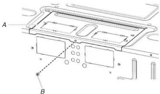
text_image
A BA. Damper plate
B. Screw
WARNING
Electrical Shock Hazard
Plug into a grounded 3 prong outlet.
Do not remove ground prong.
Do not use an adapter.
Do not use an extension cord.
Failure to follow these instructions can result in death, fire, or electrical shock.
- Plug in the microwave oven. Check if the vent fan runs with abnormal sounds, go back through the steps to see which step was skipped.
Rotate Blower Motor for Roof Venting Installation
-
Repeat Steps 1 to 5 from "Wall Venting Installation Only."
-
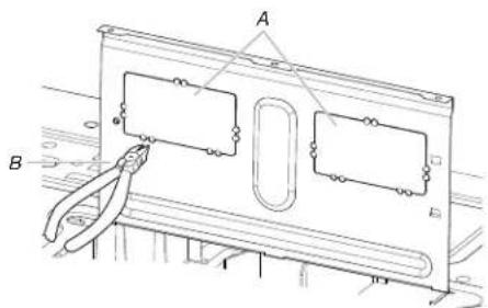
Using diagonal wire cutting pliers, gently snip out the rectangular vent covers on the damper plate at the perforations.
text_image
Technical diagram showing a mechanical assembly with labeled components A and B, including a tool inserted into a component.A. Rectangular vent covers
B. Diagonal wire cutting pliers
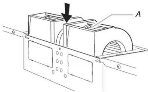
- Lower blower motor back into microwave oven. Exhaust ports face the top of microwave oven.
natural_image
Technical line drawing of a mechanical assembly with labeled component A (no text or symbols beyond label)A. Exhaust port
IMPORTANT: If blower motor is not positioned with flat side facing the back of the microwave oven (as shown), performance will be poor.
-
Reconnect the blower motor wire into the connector.
-
Reattach the 2 blower screws into the recessed holes in the back of the microwave.
-
Check to make sure the 2 screws are secured properly in the blower motor screw holes, so that the motor cannot move.
-
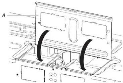
Return the damper plate to its original horizontal position.
natural_image
Technical diagram of a mechanical assembly with labeled components and directional arrows (no readable text or symbols)A. Damper plate
- Secure damper plate with screw removed in Step 1.
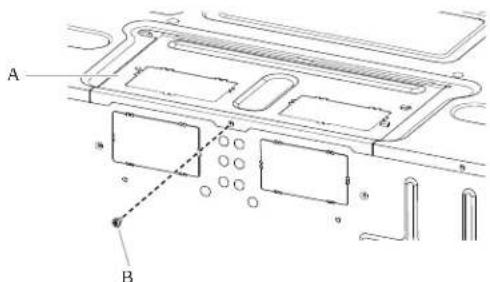
text_image
A BA. Damper plate
B. Screw
- Repeat Step 14 from "Wall Venting Installation Only."
Install Damper Assembly
If for recirculation installation, no need to install the damper assembly, this section can be skip. And save it for future use. Install Damper Assembly for Wall Venting Installation
- Check that damper blade moves freely and opens fully.
- Position the damper assembly on the back of the microwave oven so that the damper blade hinge is at the top, and the damper blade opens away from the microwave oven.
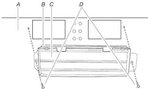
text_image
A B C DA. Back of microwave oven
B. Damper assembly
C. Damper blade D. #6 x 3/8" Sheet metal screws
- Secure damper assembly with two #6 x 3/8" sheet metal screws.
Install Damper Assembly for Roof Venting Installation
- Check that damper blade moves freely and opens fully.
- Insert damper assembly through the cabinet cutout so that the long tab of the damper assembly slides under the raised tabs of the damper plate. Then secure with #6 x 3/8" sheet metal screw.
NOTE: The screw cannot be installed if the damper assembly is not positioned as shown.
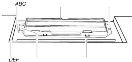
text_image
ABC DEFA. Raised tabs
D. Upper cabinet cutout
B. Damper assembly
E. Long tab
C. #6 x 3/8" Sheet metal screws
F. Damper plate
- Connect vent to damper assembly.
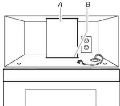
text_image
A BA. Vent
B. Damper assembly (under vent)
Install the Microwave Oven
WARNING
Excessive Weight Hazard
Use two or more people to move and install or un appliance.
Failure to do so can result in back or other injury.
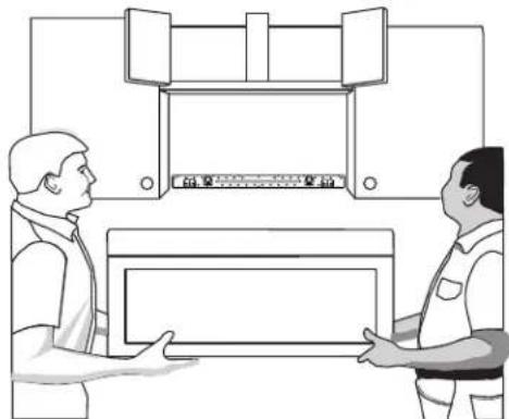
IMPORTANT: The control side of the microwave oven is the side. Handle the microwave oven gently.
- Place a washer on each 1/4-20 x 3" flat-head bolt and place inside upper cabinet near the 3/8" (10 mm) holes.
- Make sure the microwave oven door is closed and taped shut
text_image
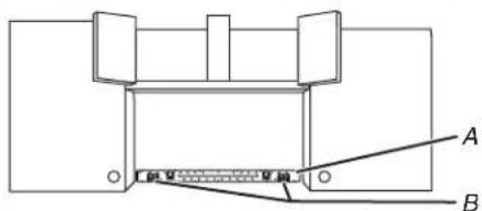
Diagram showing two workers exchanging a device with labeled components, possibly illustrating a technical or industrial process.- Using 2 or more people, lift microwave oven and hang it on support tabs at the bottom of mounting plate.
NOTE: To avoid damage to the microwave oven, do not grip or use the door or while the microwave oven is being handled.
text_image
Technical diagram showing a mechanical assembly with labeled components A and B, likely illustrating a component or assembly.A. Mounting plate
B. Support tabs
- With front of microwave oven still tilted, thread power supply cord through the power supply cord hole in the bottom of the upper cabinet.

natural_image
Simple line drawing of a ceiling-mounted cabinet with an upward arrow indicating airflow or movement (no text or symbols)- Rotate microwave oven up toward upper cabinet.
NOTE: If venting through the wall, make sure the damper assembly fits easily into the vent in the wall cutout. -
Push microwave oven against mounting plate and hold in.
NOTE: If microwave oven does not need to be adjusted, skip steps 6 through 8. -
If adjustment is required, rotate microwave oven downward. Using 2 or more people, lift microwave oven off of mounting plate, and set aside on a covered surface.
- Loosen mounting plate screws. Adjust mounting plate and retighten screws.
-
Repeat steps 3 through 6.
-
With the microwave oven centered, and with at least one person holding it in place, insert bolts through upper cabinet into microwave oven. Tighten bolts until there is no gap between upper cabinet and microwave oven.
NOTES:
■ Some upper cabinets may require bolts longer or shorter than 3" (7.6 cm). Longer or shorter bolts are available at most ce hardware stores.
■ Overtightening bolts may warp the top of the microwave oven. Nut. To avoid warping, wood filter blocks (installer to provide) may be added. The blocks must be the same thickness as the space between the upper cabinet bottom and the microwave oven.

natural_image
Line drawing of a simple indoor setup with a bed, wall-mounted sink, and electrical outlet (no text or symbols)A. Bolts
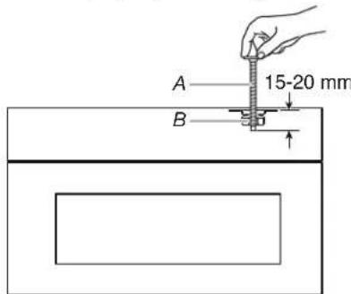
■ Avoid damage to the mounting nut, screw the bolts into the mounting nut holes around 15–20 mm by hand first, make sure the bolts thread in properly. Then tighten with tools.
text_image
A 15-20 mm BA. Bolt
B. Mounting Nut
Complete Installation
The installation is now complete.
- Check that all parts are now installed. If there is an extra leave installation instructions for future use, go back through the steps to see which step was skipped.
- Dispose of/recycle all packaging materials.
WARNING
Electrical Shock Hazard
Plug into a grounded 3 prong outlet.
Do not remove ground prong.
Do not use an adapter.
Do not use an extension cord.
Failure to follow these instructions can result in death, fire, or electrical shock.
- Plug microwave oven into grounded 3 prong outlet.
- Reconnect power.
- Check the operation of microwave oven by placing 1 cup (250 mL) of water on the cavity and programming a cook time of 1 minute at 100% power. Test vent fan and exhaust by operating the vent fan.
- Check the vent door if auto open.
- If the microwave oven does not operate:
■ Check that a household fuse has not blown, or that a circuit breaker has not tripped. Replace the fuse or reset the circuit breaker. If the problem continues, call an electrician.
■ Check that the power supply cord is plugged into a grounded 3 prong outlet.
■ See the User Instructions for troubleshooting information.
- If for roof venting and wall venting, uninstall the charcoal filter before use, by following below steps.
To uninstall the charcoal filter:
a. Disconnect power.
b. Push the finger grips back and then pull down the grease filter from the bottom plate. Set aside the grease filter. Refer to the illustration 1 for more details.
c. Pull the four hooks out to remove the charcoal filter from bottom plate. Refer to the illustration 2 for more details.
d. Put the grease filter back into the bottom plate and the springs toward the back. Push the finger grips back, until the two tongues are in position, see illustration 1.
Illustration 1
text_image
A B C DIllustration 2
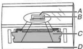
text_image
A B C DA. Tongues
B. Finger Grip
C. Grease Filter
D. Spring
A. Holes
B. Hooks
C. Charcoal Filter
D. Bottom Plate
natural_image
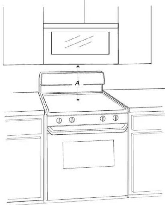
Line drawing of a kitchen oven with a mounted dish, showing top-down view and height measurement (no text or symbols)A. The height from the highest point of the stove to the bottom of the microwave oven.
| Minimum Recommendation | |
| 12 ^1/8 " (30.8 cm) 18 | ^1/8 " (46 cm) |
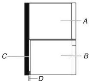
text_image
A B C DA. Cabinet
B. Microwave oven
C. Wall or back of the cabinet
D. 1/2"-3/4" (1.3-1.9 cm)
VENTING DESIGN SPECIFICATIONS
This section is intended for architectural designer and builder/contractor reference only.
NOTES:
■ Vent materials needed for installation are not provided with microwave hood combination.
■ We do not recommend using a flexible metal vent.
■ To avoid possible product damage, be sure to vent air outside, unless using recirculation installation. Do not vent exhaust air into concealed spaces, such as spaces within walls or ceilings, attics, crawl spaces or garages.
For optimal venting installation, we recommend:
■ Using roof or wall caps that have backdraft dampers.
■ Using a rigid metal vent.
■ Using the most direct route by minimizing the length of the vent and number of elbows to provide efficient performance.
■ Using uniformly sized vents.
■ Using duct tape to seal all joints in the vent system.
■ Using caulking compound to seal exterior wall or roof opening around cap.
■ Not installing 2 elbows together, for optimal hood performance.
If venting through the wall, be sure that there is proper clearance within the wall for the damper to open fully.
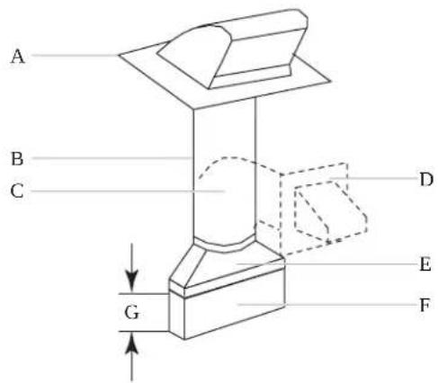
text_image
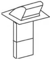
A B C D E F GA. Roof cap
B. 6" (152 mm) minimum diameter round vent
C. Elbow (for wall venting only)
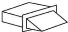
D. Wall cap
E. 3/4" x 10" to 6" (8.3 x 25.4 cm to 15.2 cm) a rectangular-to-round transition piece
F. Vent extension piece, at least 3" (7.6 cm) high
G. 3" (7.6 cm)
Recommended Standard Fittings
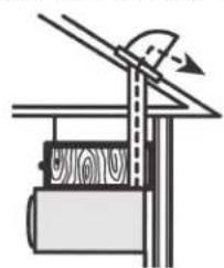
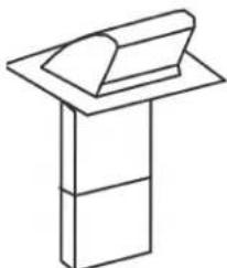
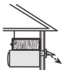
If venting through the roof, and rectangular-to-round transition is used, be sure there are at least 3" (7.6 cm) of clearance between the top of the microwave oven and the transition piece. See length. See the examples in "Recommended Vent Length." "Rectangular-to-Round Transition" illustration.
natural_image
Simple line drawing of a mechanical device with a lever and base (no text or symbols)A
natural_image
Simple line drawing of a 3D object resembling a folded paper or stand (no text or symbols)B
natural_image
Simple line drawing of a mechanical device with a cylindrical component and directional arrows (no text or symbols)C
D
A. Roof venting
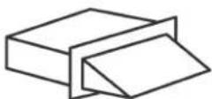
B. Roof cap
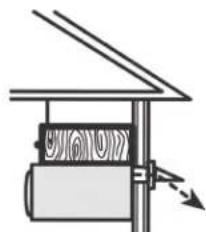
C. Wall venting
D. Wall cap
text_image
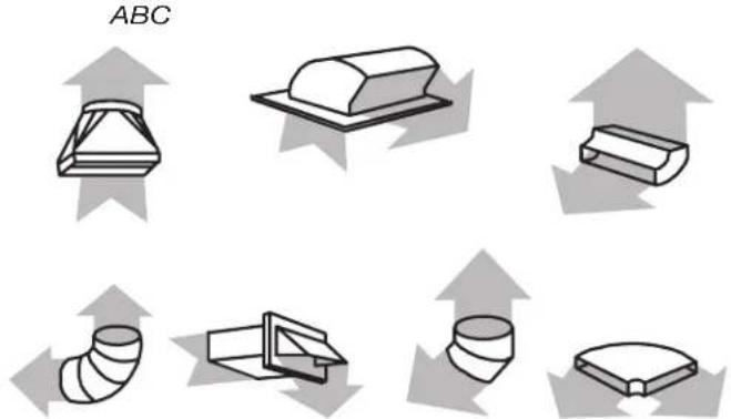
ABCDEFG
A. Rectangular-to-round transition piece: 1/3'' × 10'' to 6'' = 5 ft (8.3 x 25.4 cm to 15.2 cm = 1.5 m)
B. Roof cap: 34^ x 10" = 24 ft (8.3 x 25.4 cm = 7.3 m)
C. 90° elbow: 124 " x 10" = 25 ft (8.3 x 25.4 cm = 7.6 m)
D. 90^ elbow: 6'' = 10 ft (15.2 cm = 3 m)
E. Wall cap: 34 " x 10" = 40 ft (8.3 x 25.4 cm = 12.2 m)
F. 45^ elbow: 6'' = 5 ft (15.2 cm = 1.5 m)
G. 90^ flat elbow:1/3" x 10" = 10 ft (8.3 x 25.4 cm = 3 m)
Recommended Vent Length
A 3^1/4 " x 10" (8.3 x 25.4 cm) rectangular or 6" (15.2 cm) round vent should be used.
Rectangular-to-Round Transition
NOTE: The minimum 3" (7.6 cm) clearance must exist between the top of the microwave oven and the rectangular-to-round transition piece so that the damper can open freely and fully.
The total length of the vent system including straight vent, elbow(s), transitions and wall or roof caps must not exceed the equivalent of 140 ft (42.7 m) for either type of vent. See the "Recommended Standard Fittings" section for equivalent lengths.
For best performance, use no more than three 90° elbows.
To calculate the length of the system you need, add the equivalent lengths of each vent piece used in the system. See the following examples:
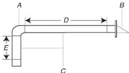
3^1/4 x 10" (8.3 x 25.4 cm) vent system = 73 ft (22.2 m) total
text_image
A D B E CA. One _4 " x 10" (8.3 x 25.4 cm) 90° elbow= 25 ft (7.6 m)
B. 1 wall cap = 40 ft (12.2 m)
C. 2 ft (0.6 m) + 6 ft (1.8 m) straight = 8 ft (2.4 m)
D. 6 ft (1.8 m)
E. 2 ft (0.6 m)
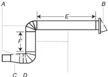
6" (152 mm) vent system = 73 ft (22.2 m) total
text_image
A E B F C DA. Two 90° elbows = 20 ft (6.1 m)
B. 1 wall cap = 40 ft (12.2 m)
C. 1 rectangular-to-round transition piece = 5 ft (1.5 m)
D. 2 ft (0.6 m) + 6 ft (1.8 m) straight = 8 ft (2.4 m)
E. 6 ft (1.8 m)
F. 2 ft (0.6 m)
If the existing vent is round, a rectangular to round transition piece must be used. In addition, a rectangular 3" (7.6 cm) extension vent between the damper assembly and rectangular to round transition piece must be installed to keep the damper from sticking.
SÉCURITÉ DU FOUR À MICRO-ONDES
text_image
WALL TEMPLATE / PLANTILLA PARA PARED UPPER CABINET TEMPLATE / PLANTILLA DEL ARMARIO SUPERIOR A0: Floor and surrounding floor A1: Upper sectional drawing floor A2: Wall working area A3: Paper outlet of sound box A4: Linger's floor A5: Tower de Balleur de la ligante portion A6: Tower de Balleur de la insulating space A7: Zone of drainage unit A8: Floor of surface of ventilation A9: Diffusion parts of drainage F G H I J K L M N O P Q R S T U V W X Y Z W X Y Z W X Y Z W X Y Z W X Y Z W X Y Z W X Y Z W X Y Z W X Y Z W X Y Z W X Y Z W X Y Z W X Y Z W Y Z W X Y Z W X Y Ztext_image
B C A E F C D A Etext_image
B A E F C D A E EE. Pattes de support
C. Axe vertical de montant de cloison
text_image
Technical diagram showing a 3D geometric structure with labeled dimensions and annotations, including points A and B.natural_image
Line drawing of a person pointing at a vertical line with labeled point A (no text or symbols beyond label)A. Axe central
text_image
Technical diagram showing mechanical assembly with labeled components and dimensions, including sectional view A and cross-sectional view with force F and torque E.text_image
A and B holesnatural_image
Pure geometric diagram of a symmetrical 3D shape with no text, numbers, or symbolsnatural_image
Technical diagram of a device with labeled components A and B, showing internal layered structure (no text or symbols beyond labels)text_image
Technical diagram of a device casing with labeled components A and B, showing internal compartments and mounting points.text_image
A B C D E F G H I J K L M N O P Q R S T U V W X Y ZA. Plaque de support du clapet
natural_image
Technical line drawing of an electronic device chassis with mounting brackets and wiring (no text or symbols)text_image
Technical diagram showing a hand connecting components labeled A and B to a mechanical or electrical component with visible wiring and mounting brackets.text_image
Technical diagram of an air conditioner unit with labeled components and airflow arrowsnatural_image
Technical line drawing of a mechanical component with labeled section A and an arrow indicating direction (no text or symbols beyond labels)text_image
Technical diagram showing a mechanical assembly with labeled components A and B, likely illustrating a cutting or fastening process.text_image
Technical diagram showing a hand connecting components labeled A and B to a mechanical or electrical component, with visible wiring and structural details.text_image
Technical diagram showing hands operating a mechanical component with labeled parts A and Btext_image
Technical diagram of an electronic device with labeled components A and B, showing internal layout and connections.A. Vis
B. Trous
text_image
Technical diagram of a mechanical or electrical component with labeled parts A and B, showing internal structure and connections.A. Vis
natural_image
Diagram of a computer monitor with two panels and directional arrows indicating movement or force (no text or symbols present)A. Plaque de support du clapet
text_image
Technical diagram showing a mechanical assembly with labeled components A and B, including a tool and pliers.natural_image
Technical line drawing of a mechanical assembly with labeled component A (no text or symbols beyond label)natural_image
Illustration of two men interacting with a control panel, no text or symbols presenttext_image
Technical diagram showing a mechanical assembly with labeled components A and BA. Plaque de montage
B. Pattes de support
natural_image
Simple line drawing of a ceiling-mounted cabinet with an upward arrow indicating airflow or movement (no text or symbols)natural_image
Line drawing of a room setup with screws, electrical outlets, and a hose (no text or symbols)A. Vis
natural_image
Diagram of a mechanical device with a lever and base, showing no text or symbolsA
natural_image
Simple line drawing of a desk with a book on top (no text or symbols)B
natural_image
Simple line drawing of a mechanical device with a spring and directional arrow (no text or symbols)C
D
text_image
A B C D E F Gflowchart
graph TD
    A["Start"] --> B["Step 1: Solid block with curved arrow"]
    B --> C["Step 2: Dashed block with curved arrow"]
    C --> D["Step 3: Solid block with curved arrow"]
    D --> E["Step 4: Solid block with curved arrow"]
    E --> F["Step 5: Solid block with curved arrow"]
    F --> G["End"]
DEFG