MTK1630P - Microwaves JennAir - Free user manual and instructions
Find the device manual for free MTK1630P JennAir in PDF.


User questions about MTK1630P JennAir
0 question about this device. Answer the ones you know or ask your own.
Ask a new question about this device
Download the instructions for your Microwaves in PDF format for free! Find your manual MTK1630P - JennAir and take your electronic device back in hand. On this page are published all the documents necessary for the use of your device. MTK1630P by JennAir.
USER MANUAL MTK1630P JennAir
MICROWAVE OVEN BUILT-IN TRIM KIT INSTALLATION INSTRUCTIONS
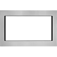
Built-In Trim Kit Models MTK1627P, MTK1630P, MTK2227P, MTK2230P
UL listed for use over any electric or gas built-in oven, up to 30^ (76.2 cm) wide
INSTRUCTIONS D'INSTALLATION DE LA TROUSSE DE GARNITURE DU FOUR À MICRO-ONDES ENCASTRE
| MICROWAVE OVEN SAFETY | 1 |
| INSTALLATION INSTRUCTIONS | 2 |
| Tools and Parts | 2 |
| Location Requirements | 2 |
| Required Cutout Dimensions | 2 |
| Trim Kit Frame Dimensions | 3 |
| Electrical Requirements | 3 |
| Prepare Microwave Oven | 4 |
| Prepare Cutout/Cabinet Opening | 4 |
| Install the Microwave Oven | 5 |
| Install Trim Kit Frame | 6 |
Your safety and the safety of others are very important.
We have provided many important safety messages in this manual and on your appliance. Always read and obey all safety messages.

This is the safety alert symbol.
This symbol alerts you to potential hazards that can kill or hurt you and others.
All safety messages will follow the safety alert symbol and either the word "DANGER" or "WARNING."
These words mean:
DANGER
WARNING
You can be killed or seriously injured if you don't immediately follow instructions.
You can be killed or seriously injured if you don't follow instructions.
All safety messages will tell you what the potential hazard is, tell you how to reduce the chance of injury, and tell you what can happen if the instructions are not followed.
INSTALLATION INSTRUCTIONS
Tools and Parts
Tools Needed
Gather the required tools and parts before starting installation. Read and follow the instructions provided with any tools listed here.
Measuring tape
■ Drill
Pencil
7/64" drill bit
Phillips screwdriver
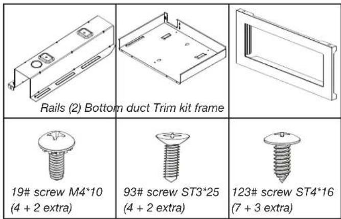
Parts Supplied (not shown to scale)
Location Requirements
The microwave oven may be installed over a built-in oven. If installing over a built-in oven, make sure there is a minimum of 3^15 / 6 (10 cm) between the top of the lower oven cutout and the microwave oven cutout floor.
The microwave oven may also be installed in a cabinet by itself (without a built-in oven below). For best usability, we recommend a minimum distance of 36^ / 16^ (91.6 cm) from the floor to the cutout floor.
Make sure the surrounding cabinetry has clearance to open and close freely. Allow a clearance of at least 2^ (5.1 cm) below the cutout floor ( 3^15 / 16 [10 cm] for installation above a built-in oven), and a clearance of at least 2^ (5.1 cm) above the cutout opening.
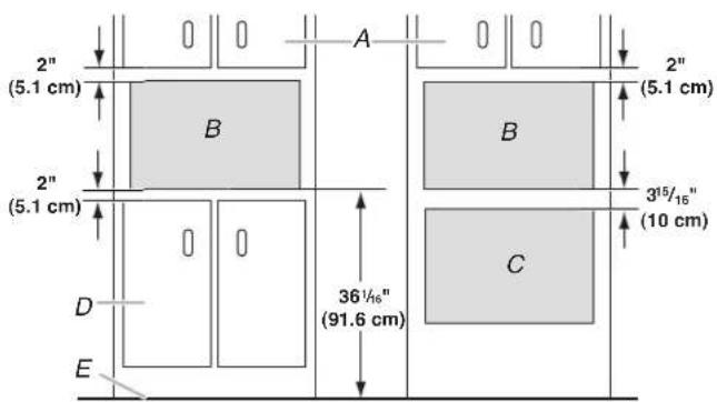
A. Upper cabinet
C. Lower oven cutout
B. Microwave oven cutout
D. Lower cabinets
E. Floor
Required Cutout Dimensions-1.6 cuft.
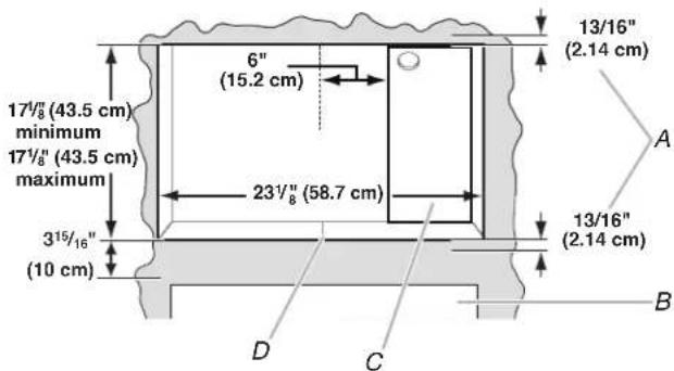
For minimum depth requirements, see chart
Required Cutout Dimensions-2.2 cuft
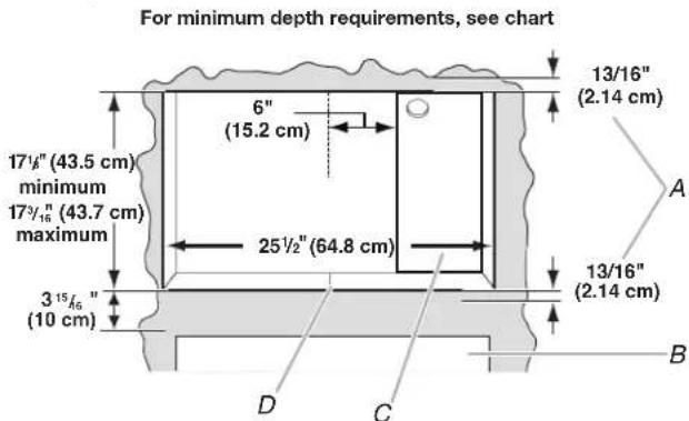
A. Trim kit frame overhang
B. Cutout for lower oven
C. Recommended region for receptacle location (no less than 6^ [15.2 cm] to the right of cutout centerline)
D. Cutout centerline
1.6 cuft.
| Receptacle Location Minimum Depth | |
| Within recommended region | 20" (50.8 cm) with flush receptacle; 23" (58.4 cm) with non-flush receptacle |
| Outside recommended region | 23" (58.4 cm) with flush receptacle; 26" (66.0 cm) with non-flush receptacle |
2.2 cuft.
| Receptacle Location Minimum Depth | |
| Within recommended region | 223/4" (57.8 cm) with flush receptacle; 263/4" (67.9 cm) with non-flush receptacle |
| Outside recommended region | 263/4" (67.9 cm) with flush receptacle; 303/4" (78.1 cm) with non-flush receptacle |
NOTES:
- Depth requirements depend upon receptacle and its location within or outside of recommended region. See illustration and chart above.
Height dimension is critical: 147(43.5cm) minimum, 17^3 / 6^n (43.7 cm) maximum.
Width measurement has ± 1 / 16 (2 mm) tolerance.
15^8'' (10 cm) minimum dimension is from lower oven cutout ceiling to microwave oven cutout floor. - Trim kit frame extends 13 / 16" (2.14 cm) above and below the cutout opening.
Trim Kit Frame Dimensions-1.6 cuft
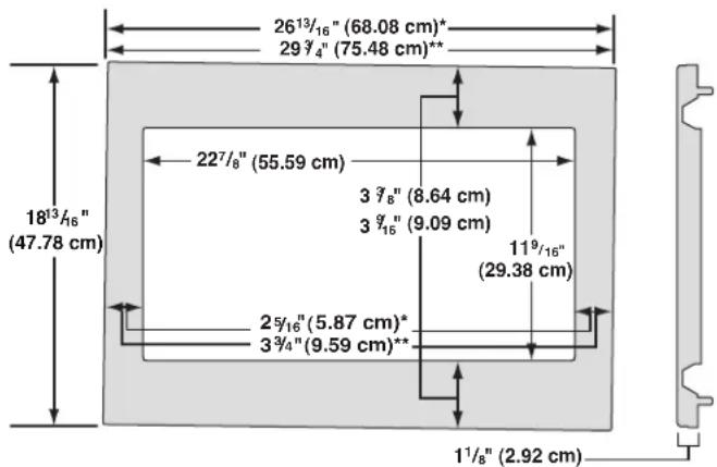
27" (68.6 cm) trim kit
*30" (76.2 cm) trim kit
Trim Kit Frame Dimensions-2.2 cuft
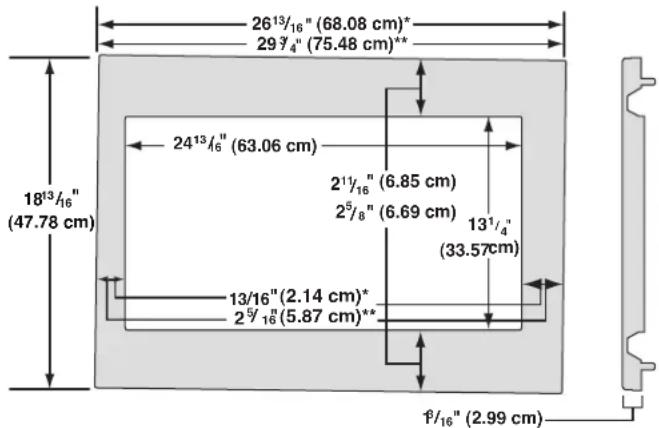
27" (68.6 cm) trim kit
*30" (76.2 cm) trim kit
Electrical Requirements
Observe all governing codes and ordinances.
Required:
A 120V 60 Hz, AC only, 15 or 20 A electrical supply with a fuse or circuit breaker.
Recommended:
A time-delay fuse or time-delay circuit breaker.
A separate circuit serving only this microwave oven.
GROUNDING INSTRUCTIONS
For all cord connected appliances:
The microwave oven must be grounded. In the event of an electrical short circuit, grounding reduces the risk of electric shock by providing an escape wire for the electric current. The microwave oven is equipped with a cord having a grounding wire with a grounding plug. The plug must be plugged into an outlet that is properly installed and grounded.
WARNING: Improper use of the grounding plug can result in a risk of electric shock. Consult a qualified electrician or serviceman if the grounding instructions are not completely understood, or if doubt exists as to whether the microwave oven is properly grounded.
Do not use an extension cord. If the power supply cord is too short, have a qualified electrician or serviceman install an outlet near the microwave oven.
SAVE THESE INSTRUCTIONS
Prepare Microwave Oven
WARNING
Excessive Weight Hazard
Use two or more people to move and install microwave oven.
Failure to do so can result in back or other injury.
- Install gasket before proceeding with installation. (PMMA Frame only)
- Unplug microwave oven before proceeding with installation.
- Remove any loose items inside microwave oven.
- Gently turn microwave oven onto its top, with the door facing forward (toward installer).
- Align the two rails on the microwave oven bottom, as shown, making sure the flanges are forward and pointing up.
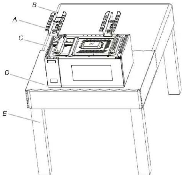
A. Rails (2)
D. Table cloth
B. 19# screws (4)
E. Table
C. Bottom duct
- Secure the rails to the microwave oven bottom using four short screws.
Prepare Cutout/Cabinet Opening
- On the cutout floor, find and mark the centerline.
- Place the bottom duct in the opening, with the flange resting against the bottom front facing of the opening.
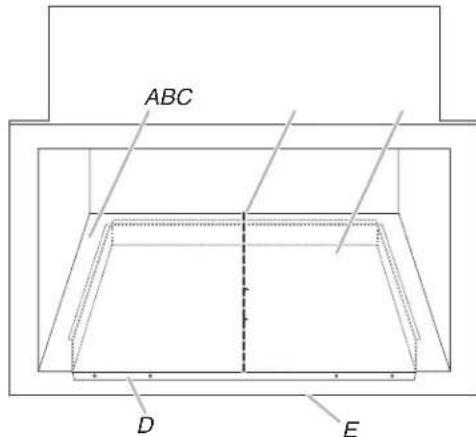
A. Cutout floor
D. Bottom duct flange
B. Centerline
E. Front facing
C. Bottom duct
- Align the center arrows on the bottom duct with the centerline drawn in Step 1 above.
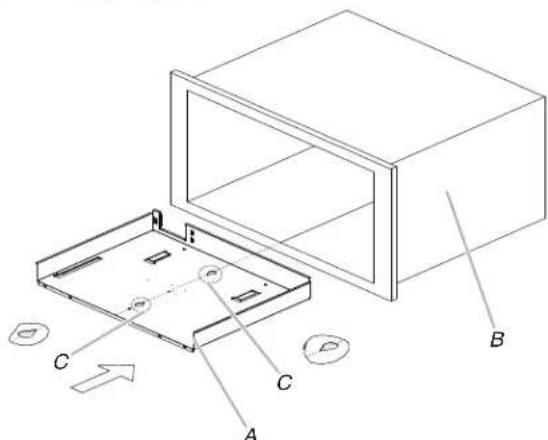
A. Bottom duct
B. Cabinet
C. Center arrows, aligned with centerline
- Mark the three mounting holes through the bottom duct onto the cutout floor.
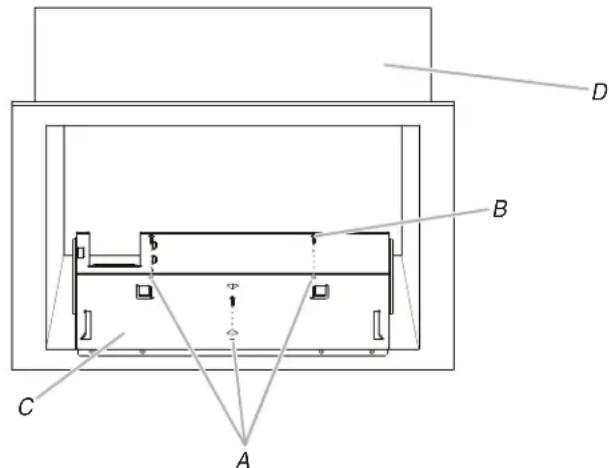
A. Bottom duct mounting holes
C. Bottom duct
B. 123# screws (3)
D. Cabinet
- Using 7 / 64'' (0.28 cm) drill, drill pilot holes into the three holes marked in Step 4.
- Realign and install the bottom duct with three short screws.
- Using 7/64'' (0.28 cm) drill, drill pilot holes through the four mounting holes of the bottom duct flange into the bottom front facing of the cutout/cabinet opening.
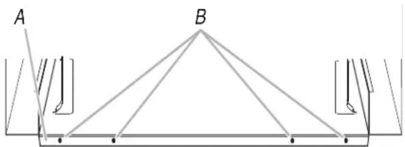
A. Bottom duct flange
B. Mounting holes
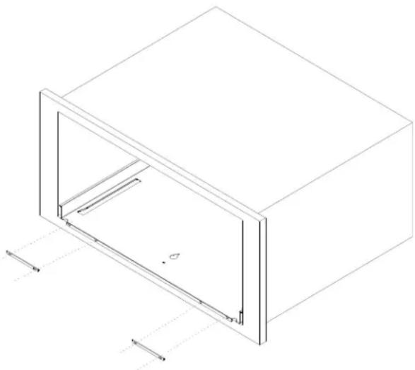
- Align the spacer holes with the bottom duct holes and proceeding with installation.
This step can be built in by using one of following trim kits.
| Kit Size Kit Model Numbers/Color |
| 27"(68.6cm) MTK1627PB/Black |
| 30"(76.2cm) MTK1630PB/Black |
| 27"(68.6cm) MTK2227PB/Black |
| 30"(76.2cm) MTK2230PB/Black |
Install the Microwave Oven
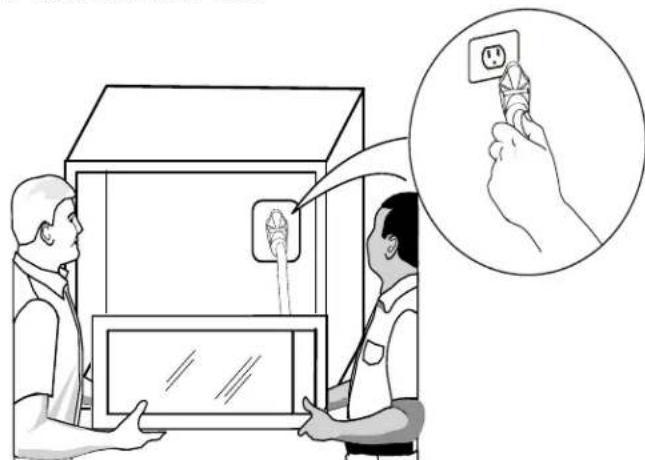
- Gently return microwave oven to its upright position.
- Position microwave oven near cutout opening.

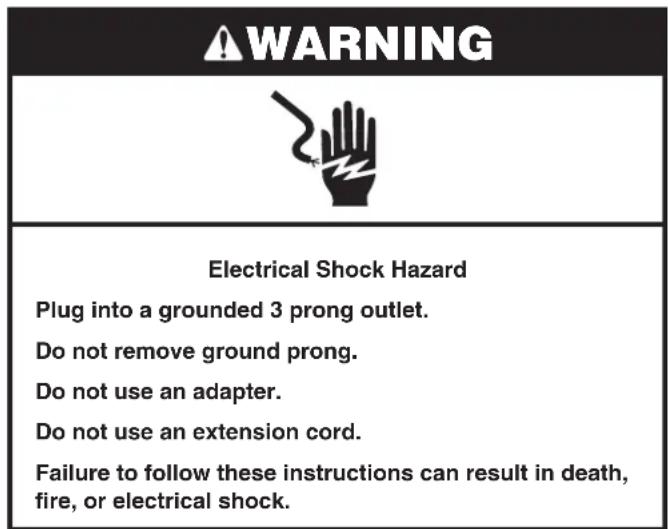
WARNING
Electrical Shock Hazard
Plug into a grounded 3 prong outlet.
Do not remove ground prong.
Do not use an adapter.
Do not use an extension cord.
Failure to follow these instructions can result in death, fire, or electrical shock.
- Plug in microwave oven.
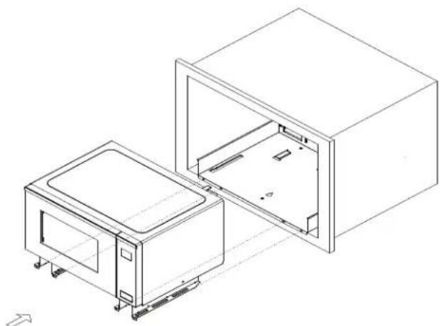
- Slide the microwave oven back and into place. The mounting holes of the rail flanges and bottom duct flange will align against the bottom front facing of the cutout/cabinet opening.
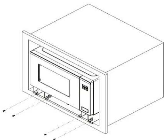
- Secure the microwave oven to the cutout/cabinet by installing four short screws into the mounting holes.
Install Trim Kit Frame
- Position trim kit frame over the opening so that the lower tabs rest on the cutout floor, as shown.
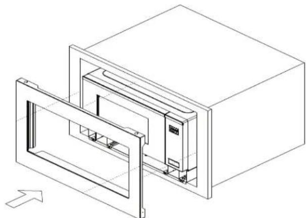
- Holding the trim kit frame in place, use 7/64" (0.28 cm) drill to drill four pilot holes into the front facing of the cutout/cabinet through the mounting hole guides in the upper and lower corners of the trim kit frame.
NOTES:
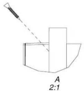
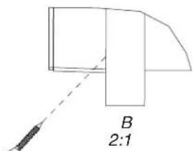
The holes will be drilled downward from the top, and upward from the bottom at an angle of about 45^ .
To avoid damage to the trim kit frame, do not overtighten screws.
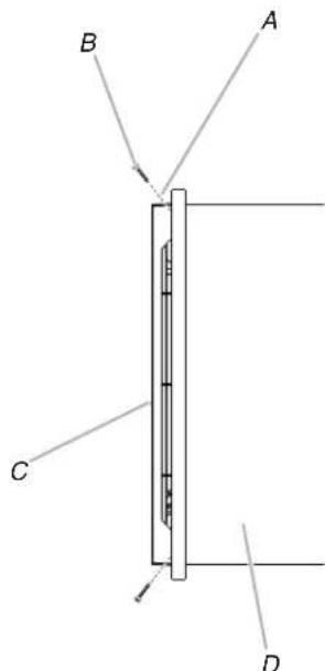
A. Mounting hole guide
C. TK Frame
B. 93# screw (4 - painted)
D. Cabinet
- Secure trim kit frame to cutout/cabinet by installing four long wood screws (painted) into the pilot holes drilled in Step 2 above.
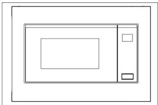
Installation is now complete. Replace any loose items that have been removed from microwave oven cavity.
Save these Installation Instructions for future reference.