
E43929 - Industrial cooling accessory IFM - Free user manual and instructions
Find the device manual for free E43929 IFM in PDF.


User questions about E43929 IFM
0 question about this device. Answer the ones you know or ask your own.
Ask a new question about this device
Download the instructions for your Industrial cooling accessory in PDF format for free! Find your manual E43929 - IFM and take your electronic device back in hand. On this page are published all the documents necessary for the use of your device. E43929 by IFM.
USER MANUAL E43929 IFM
Operating instructions
Cooling adapter for G1/2 welding adapter
E43929
Contents
1 Preliminary note 3
1.1 Symbols used 3
1.2 Warnings.... 3
2 Safety instructions.... 4
3 Intended use.... 5
4 Installation.... 6
4.1 Cooling 7
4.2 Use on tanks.... 7
4.3 Use on pipes and inline housings 8
5 Disposal 9
1 Preliminary note
You will find instructions, technical data, approvals and further information using the QR code on the unit / packaging or at documentation.ifm.com.
1.1 Symbols used
√ Requirement
Instructions
Reaction, result
[...] Designation of keys, buttons or indications
→ Cross-reference

Important note
Non-compliance may result in malfunction or interference.

Information
Supplementary note
1.2 Warnings
Warnings indicate the possibility of personal injury and damage to property. This enables safe product handling. Warnings are graded as follows:

WARNING
Warning of serious personal injury
▷ If the warning is not observed, fatal and serious injuries are possible.

CAUTION
Warning of minor to moderate personal injury
▷ If the warning is not observed, minor to moderate injuries are possible.
ATTENTION
Warning of damage to property
▷ If the warning is not observed, damage to property is possible.
2 Safety instructions
- Read this document before setting up the product and keep it during the entire service life.
- The product must be suitable for the corresponding applications and environmental conditions without any restrictions.
- Only use the product for its intended purpose (→ Intended use).
- If the operating instructions or the technical data are not adhered to, personal injury and/or damage to property may occur.
- The manufacturer assumes no liability or warranty for any consequences caused by tampering with the product or incorrect use by the operator.
- Installation, set-up, operation and maintenance of the product must be carried out by qualified personnel authorised by the machine operator.
- When using water cooling in a welding process, make sure that the coolant does not come to a standstill to prevent it from overheating.
- The cooling must not lead to the formation of condensate on the surface of the welding adapter, otherwise the welding process will be impeded.
3 Intended use
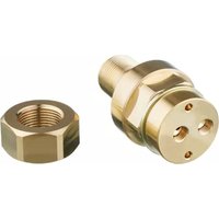
The cooling adapter for G1/2 welding adapters absorbs the heat energy during the welding process via the flowing coolant and dissipates it, thus optimising dimensional accuracy.
4 Installation

CAUTION
During the welding operation, the welding adapter, the surrounding material and the cooling adapter can increase in temperature to over 65\ °C ( 149\ °F ).
▷ Risk of burns.
▶ Allow all components to cool down.

Fig. 1: Cooling adapter with optional welding adapter.
1: Internal water cooling
2: Seal
3: External water cooling
4: Optional welding adapter (not included)
5: Nut

Fig. 2: Cooling adapter (connections, flexible hose lines not included).
6: Internal thread G 1/8 for flexible hose connections
▶ Screw the cooling adapter into the adapter to be welded in. Use on tanks, Use on pipes and inline housings ( → ☐ 8)
▶ For tank applications, fit the locknut.
▶ Fix the adapter, ensure the supply of forming gas and attach the connections and flexible hoses to the internal threads of the cooling adapter, activate the cooling. Cooling ( → ☐ 7)
4.1 Cooling
The cooling must not lead to the formation of condensate on the surface of the welding adapter, otherwise the welding process will be impeded.
▶ Circulation of the coolant must be ensured during welding.
▶ Even with internal cooling, professional welding with sufficient cooling time between the welding steps (back-step welding) is mandatory.
▶ The tightness of the flexible hose connections must be ensured so that no coolant comes into contact with the weld seam.
▶ The cooling effect must be checked by a supervising welding specialist and monitored during the welding process.
4.2 Use on tanks
The cooling adapter and the nut are to be used provided the tank is accessible from the inside after the welding process.
▶ Screw the cooling adapter into the adapter to be welded in until it is hand-tight.
▶ Screw the nut from the inside of the tank onto the cooling adapter.
▶ Activate cooling.
▶ Carry out the welding operation → Installation instructions Welding adapter.
▶ After each welding, including the cooling phase, check the thread of the welding adapter for ease of movement.
▶ After cooling, unscrew the nut from the cooling adapter.
▶ After cooling, remove the cooling adapter from the welding adapter and check that the thread and sealing edge are not damaged.
4.3 Use on pipes and inline housings

Mount the cooling adapter so that it does not touch the opposite wall.
▶ Screw the cooling adapter hand-tight into the welding adapter.
▶ Activate cooling.
▶ Carry out the welding operation → Installation instructions Welding adapter.
▶ After each welding, including the cooling phase, check the thread of the welding adapter for ease of movement.
▶ After cooling, remove the cooling adapter from the welding adapter and check that the thread and sealing edge are not damaged.
5 Disposal
▶ After use dispose of the product or components in an environmentally friendly way in accordance with the applicable national regulations.
Brand : IFM
Model : E43929
Category : Industrial cooling accessory