QWR04DGRGB - Wine cellar HAIER - Free user manual and instructions
Find the device manual for free QWR04DGRGB HAIER in PDF.

User questions about QWR04DGRGB HAIER
0 question about this device. Answer the ones you know or ask your own.
Ask a new question about this device
Download the instructions for your Wine cellar in PDF format for free! Find your manual QWR04DGRGB - HAIER and take your electronic device back in hand. On this page are published all the documents necessary for the use of your device. QWR04DGRGB by HAIER.
USER MANUAL QWR04DGRGB HAIER
Installation and User Manual
natural_image
Exterior view of a black and silver Holar air fryer cabinet (no text or symbols visible on the cabinet body)TABLE OF CONTENTS
SAFETY INFORMATION 3
USING THE APPLIANCE
Controls and Features: Wine Chiller
Temperature Control 7
Loading 8
CARE AND CLEANING....9
INSTALLATION INSTRUCTIONS 10
TROUBLESHOOTING TIPS 15
LIMITED WARRANTY....19
RECORD KEEPING....20
SAFETY INFORMATION
ATTENTION CONSUMER!
This appliance is designed for storing and cooling wine. Do not store perishable foods in this unit.
WARNING
To reduce the risk of fire, explosion, electric shock, or injury when using your appliance, follow these basic safety precautions:
- Use this appliance only for its intended purpose as described in this Owner's Manual.
- This appliance must be properly installed and located in accordance with the Installation Instructions before it is used.
- Unplug the appliance before making repairs or cleaning.
NOTE: Power to the appliance cannot be disconnected by any setting on the control panel.
NOTE: Repairs must be performed by a qualified Service Professional. - Replace all parts and panels before operating.
- Do not store or use gasoline or other flammable vapors and liquids in the vicinity of this or any other appliance.
- Do not store explosive substances such as aerosol cans with a flammable propellant in this appliance.
- Do not use an extension cord.
-
To prevent suffocation and entrapment hazards to children, remove door from this appliance before disposing of it or discontinuing its use.
-
To avoid serious injury or death, children should not stand on, or play in or with the appliance.
- Children and persons with reduced physical, sensory or mental capabilities or lack of experience and knowledge can use this appliance only if they are supervised or have been given instructions on safe use and understand the hazards involved.
- This appliance is intended to be used in household and similar applications such as: staff kitchen areas in shops, offices and other working environments; farm houses; by clients in hotels, motels, bed & breakfast and other residential environments; catering and similar non-retail applications.
- Do not apply harsh cleaners to the appliance. Certain cleaners will damage plastic which may cause parts such as the door or door handles to detach unexpectedly. See the Care and Cleaning section for detailed instructions.
CAUTION
To reduce the risk of injury when using your appliance, follow these basic safety precautions.
- Keep fingers out of the "pinch point" areas; clearances between the doors and between the doors and cabinet are necessarily small. Be careful closing doors when children are in the area.
- This unit is designed for storing and cooling wine. Do not store perishable foods in this unit.
SAFETY INFORMATION
INSTALLATION
EXPLOSION HAZARD
Keep flammable materials and vapors away from appliance. Failure to do so can result in fire, explosion, or death.
FIRE OR EXPLOSION HAZARD Flammable Refrigerant
This appliance contains isobutane refrigerant, also known as R600a, a natural gas with high environmental compatibility. However, it is also combustible. Adhere to the warnings below to reduce the risk of injury or property damage.
- When handling, installing and operating the appliance, care should be taken to avoid damage to the refrigerant tubing.
- Service shall only be performed by authorized service personnel. Use only manufacturer-authorized service parts.
- Dispose of appliance in accordance with the Federal and Local Regulations. The flammable refrigerant and insulation material used in this product require special disposal procedures. Contact your local authorities for the environmentally safe disposal of your appliance.
- Keep ventilation openings in the appliance enclosures or
in the built-in structure clear of obstruction.
- To remove frost, scrape with a plastic or wood spatula or scraper. Do not use an ice pick or a metal or sharp-edged instrument as it may puncture the appliance liner and then the flammable refrigerant tubing behind it.
- Do not use electrical appliances inside the storage compartment of the appliance.
- Do not use any electrical device to defrost your appliance.
CONNECTING ELECTRICITY
Electrical Shock Hazard.
Plug into a grounded 3-prong outlet.
Do not remove the ground prong.
Do not use an adapter.
Do not use an extension cord with this appliance.
Failure to follow these instructions can result in death, fire, or electrical shock.
Do not, under any circumstances, cut or remove the third (ground) prong from the power cord.
For personal safety, this appliance must be properly grounded.
The power cord of this appliance is equipped with a 3-prong (grounding) plug which mates with a standard 3-prong (grounding) wall outlet to minimize the possibility of electric shock hazard from this appliance.
Have the wall outlet and circuit checked by a qualified electrician to make sure the outlet is properly grounded.
If you have only a standard 2-prong wall outlet, it is your personal responsibility and obligation to have it replaced with a properly grounded 3-prong wall outlet.
NOTE: GFI (ground fault interrupter) is not recommended.
The appliance should always be plugged into its own individual electrical outlet which has a voltage rating that matches the rating plate.
This provides the best performance and also prevents overloading house wiring circuits which could cause a fire hazard from overheated wires.
Never unplug your appliance by pulling on the power cord. Always grip plug firmly and pull straight out from the outlet.
Immediately discontinue use of a damaged supply cord. If the supply cord is damaged, it must be replaced by a qualified service professional with an authorized service part from the manufacturer.
When moving the appliance away from the wall, be careful not to roll over or damage the power cord.
SAFETY INFORMATION
PROPER DISPOSAL OF THE WINE CHILLER
WARNING
SUFFOCATION AND ENTRAPMENT HAZARD
Failure to follow these disposal instructions can result in death or serious injury
IMPORTANT: Child entrapment and suffocation are not problems of the past. Junked or abandoned appliances or freezers are still dangerous even if they will sit for “just a few days.” If you are getting rid of your old appliance, please follow the instructions below to help prevent accidents.
Before You Throw Away Your Old Appliance
• Take off the door.
- Leave the shelves in place so that children may not easily climb inside.
Refrigerant and Foam Disposal:
Dispose of appliance in accordance with Federal and Local Regulations. Flammable refrigerant and insulation material used require special disposal procedures. Contact your local authorities for the environmentally safe disposal of your appliance.
USING THE APPLIANCE
CONTROLS AND FEATURES - WINE CENTER
TEMPERATURE CONTROL
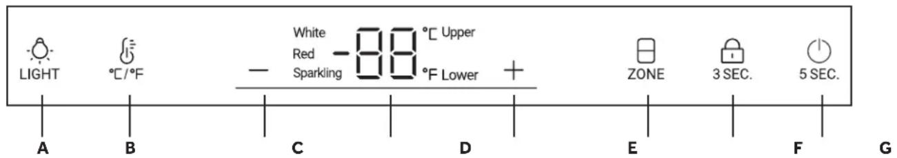
A - INTERIOR LIGHT
B - °C /°F CONVERSION
C - TEMPERATURE ADJUST: DOWN
D - DISPLAY
E - TEMPERATURE ADJUST: UP
F - TEMPERATURE ZONE SELECTION
G - LOCK BUTTON
H - POWER BUTTON
LOCKING / UNLOCKING CONTROL PANEL
The control lockout feature prevents unwanted changes to the settings of the wine center. Press and hold the 3SEC. for 3 seconds to lock / unlock the control panel.
The wine chiller has two zones. The operating temperature of both zones is from 41^ F ( 5^ C) to 61^ F ( 16^ C).
This product is designed for storing and cooling wine. It is not intended for storage of perishable foods.
As with any refrigeration-type product, there is a slight temperature variance at different locations within each zone.
Do not install the wine chiller where the temperature will go below 55^ F ( 13^ C) or above 90^ F ( 32^ C).
INTERIOR LIGHT
Press the LIGHT button to turn the cabinet lights on. The lights will turn on gradually. Press the LIGHT button again and the lights will gradually turn off.
°C /°F CONVERSION
Press the 12 button to switch between Fahrenheit and Celsius.
TEMPERATURE SETTING
Before changing the temperature press the ☐ button to select the appropriate zone. Upper or Lower will show on the display.
Press the - key or + key to decrease or increase the desired temperature in increments of one degree.
Do not set the zone to a temperature that is higher than the room temperature. The wine chiller will not achieve the desired temperature.
POWER
Press and hold the _5SEC button for 5 seconds to power on or off the wine chiller.
Sabbath Mode
Press and hold the - key and the + key for 5 seconds to enter or exit Sabbath Mode. The display will show SA when in Sabbath Mode.
Door Alarm
If the door is left open for more than 1 minute, the door alarm will sound until door is closed. The door alarm can be turned off by pressing any button on the control.
USING THE APPLIANCE
CONTROLS AND FEATURES (cont.)
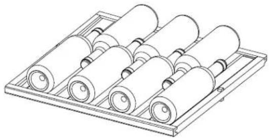
LOADING WINE BOTTLES ON THE TOP THREE WOOD SHELVES
The wine chiller has three slide out wood shelves. These shelves can hold two bottles deep, with bottle necks alternating front to back.
natural_image
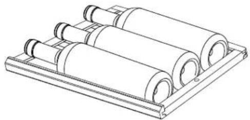
Technical line drawing of a mechanical assembly with multiple cylindrical rollers arranged in a tray (no text or symbols)LOADING WINE BOTTLES ON THE BOTTOM SHELF
Store bottles on the bottom shelf with the necks facing left or right. This area can be used for larger bottle storage like magnum bottles.
natural_image
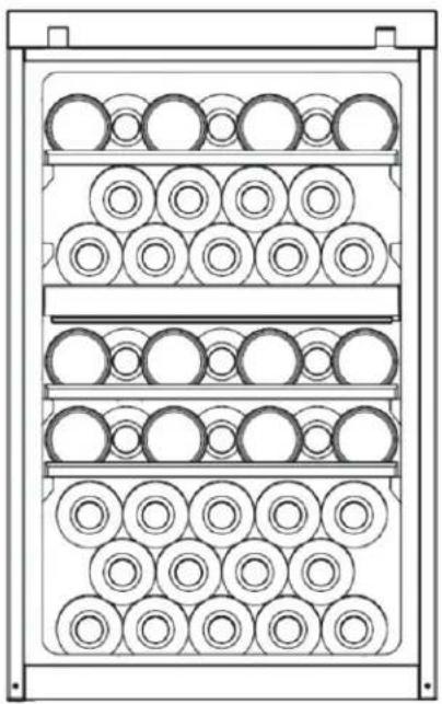
Technical line drawing of a mechanical assembly with multiple cylindrical components mounted on a base plate (no text or symbols)STACKING WINE BOTTLES
The wine chiller can store 44 regular bottles with a diameter of 3.0" (76mm) using the loading configuration below and the bottom shelf removed.
natural_image
Technical line drawing of a multi-tiered storage unit with circular components (no text or symbols)CARE AND CLEANING
CLEANING THE OUTSIDE
WARNING

Electrical Shock Hazard
Unplug the wine chiller before cleaning..
Directions for Cleaning Outside Surfaces, Door Handles, and Trim
| DO USE DO NOT USE | |
| Soft, clean cloth or sponge | Abrasive cloths, scrubbing sponges, scouring or steel wool pads |
| Mild detergent mixed with warm water | Abrasive powders or sprays Window Sprays or AmmoniaCitrus or plant oil-based cleanersAcidic or vinegar-based cleanersOven cleanersCleaners containing acetone (propanone)Any cleaner with WARNING about plastic contact |
CLEANING THE INSIDE
The vinyl door gasket may be cleaned with mild soap and water or a baking soda solution. Rinse well.
After cleaning the door gasket, apply a thin layer of paraffin wax or petroleum jelly to the door gasket at the hinge side. This helps keep the gasket from sticking and bending out of shape.
Use a slightly damp cloth or sponge when cleaning the wood shelves and areas around the lights.
Use warm water and baking soda solution—about a tablespoon (15 ml) of baking soda to a quart (1 liter) of water. This both cleans and neutralizes odors. Thoroughly rinse and wipe dry.
Other parts of the wine chiller unit—can be cleaned the same way.
Do not use detergents, scouring powders, spray cleaners or other harsh chemicals to clean the interior.
AUTOMATIC DEFROSTING
WARNING
Risk of Fire or Explosion.
Flammable Refrigerant Used..
This product defrosts automatically.
Do not use an ice pick or a metal or sharp-edged instrument to accelerate the defrosting process as it may puncture the appliance liner and then the flammable refrigerant tubing behind it.
Do not use any electrical device to defrost your appliance.
NOTE: The drain pan above the compressor may be full following defrost. Check to make sure no water spills when moving the unit.
IN THE EVENT OF A POWER FAILURE
If the power fails, open the door as infrequently as possible to maintain the temperature.
INSTALLATION INSTRUCTIONS
BEFORE YOU BEGIN
Read these instructions completely and carefully.
. IMPORTANT — Save these instructions for local inspector's use.
- IMPORTANT — Observe all governing codes and ordinances.
- Note to Installer – Be sure to leave these instructions with the Consumer.
- Note to Consumer – Keep these instructions for future reference.
WARNING
This appliance must be properly grounding the Wine Chiller."
- If you received a damaged wine chiller, you should immediately contact your dealer or builder.
- Skill Level – Installation requires basic mechanical skills. Proper installation is the responsibility of the installer. Product failure due to improper installation is not covered under the GE Appliance Warranty.
TOOLS REQUIRED
• #2 Phillips screwdriver
- 5/16" (8mm) Hex nut driver
PARTS INCLUDED
ALTERNATE HINGE CAM
ALTERNATE DOOR CAM
ALTERNATE HINGE COVER
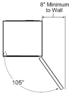
PRODUCT CLEARANCES
The wine chiller is factory set for a 105° door swing.
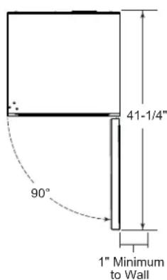
When installed in a corner:
- Allow 1" min. clearance on the hinge side for the 90° door swing and to allow racks to slide out.
- Allow 8" minimum clearance on the hinge side for a full 105° door swing.
Choose the location:
- Do not install the appliance where the temperature will go below 55^ (13°C) because it will not run often enough to maintain proper temperatures.
- Do not install the appliance where the temperature will go above 90^ (32°C) because it will not perform properly.
- Do not install the appliance in a location exposed to water (rain, etc.) or direct sunlight.
- These products are not designed to be stacked one over the other.
INSTALLATION INSTRUCTIONS
INSTALLATION SPACE
This is a freestanding wine chiller. The following air clearances are required around the product.
Top - 2" (50.8mm)
Back - 2" (50.8mm)
Sides - 1" (25.4mm)
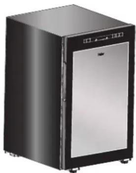
Product Dimensions
Height: 32.3in (82.0cm)
Width: 19.6in (49.7cm)
Depth: 23.0in (58.5cm)
natural_image
Exterior view of a modern black and silver refrigerator with front panel (no visible text or symbols)Additional Specifications
- A 120 volt 60Hz., 15 or 20 amp power supply is required. An individual properly grounded branch circuit or circuit breaker is
recommended. Install a properly grounded 3-prong electrical receptacle recessed into the back wall as shown. Electrical must be located on rear wall as shown.
NOTE: GFI (ground fault interrupter) is not recommended.
REMOVE PACKAGING
- Remove all packing material, tape and protective plastic coverings.
▲WARNING
Small objects are a choke hazard for
children. Remove and discard any parts not used.
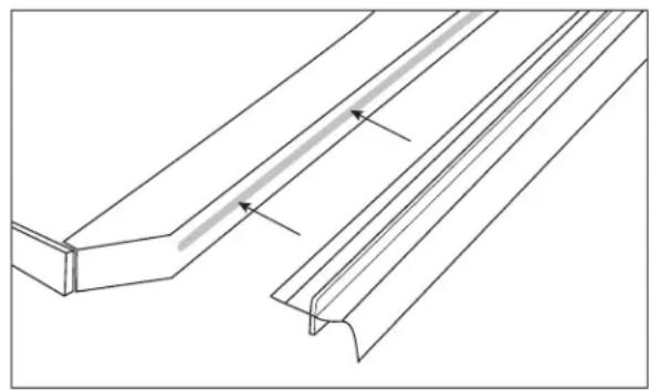
INSTALL GASKET
- Push gasket into center rail. The gasket helps with temperature performance.
natural_image
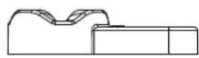
Technical line drawing of a structural component with two parallel grooves and a central notch (no text or symbols)DOOR REVERSAL INSTRUCTIONS
- Open the door and unsnap the front trim on the cabinet. Find the insert on the left side of the trim and move it to the gap on the right side of the trim.
natural_image
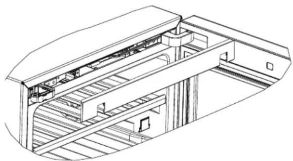
Technical line drawing of a mechanical assembly with ladder and frame (no text or symbols)UNPLUG WIRE CONNECTION
- Unplug the wire connection cable at the top of the cabinet.
natural_image
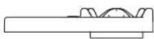
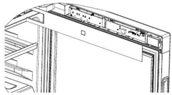
Line drawing of a mechanical assembly with no visible text or symbolsINSTALLATION INSTRUCTIONS
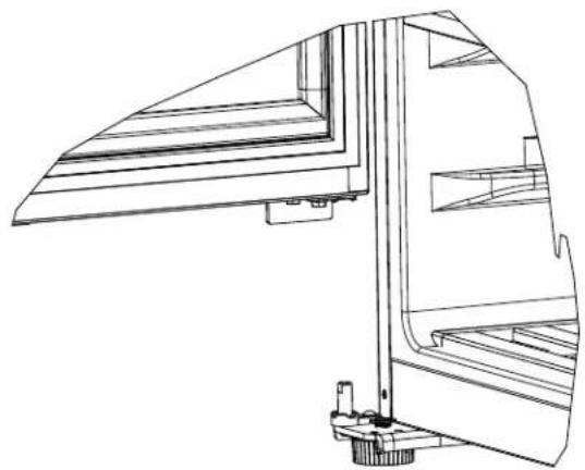
Pull-out the upper part of the door gasket, and unsnap the trim on the back side of the door. (Remove from the left side opening)
natural_image
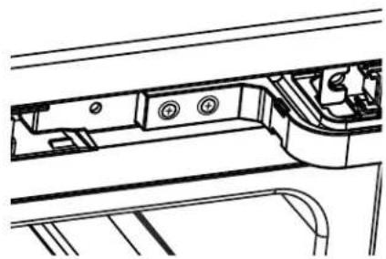
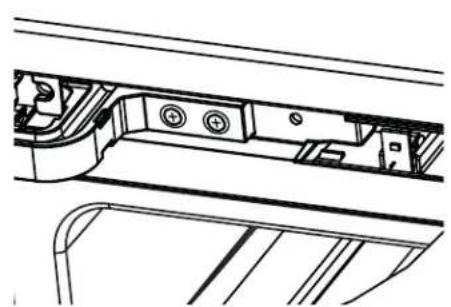
Technical line drawing of a mechanical assembly with internal components (no text or symbols)REMOVE SCREWS FROM TOP HINGE
Remove 2 screws from the top hinge and lift the door off of the bottom hinge. Remove the plastic hinge cover from the top hinge and then remove the top hinge from the door.
natural_image
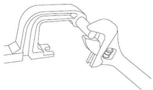
Technical line drawing of a mechanical assembly with no visible text or symbolsREVERSING TOP HINGE
Use a wrench to unscrew the hinge shaft. Install the shaft on the opposite side of the hinge
natural_image
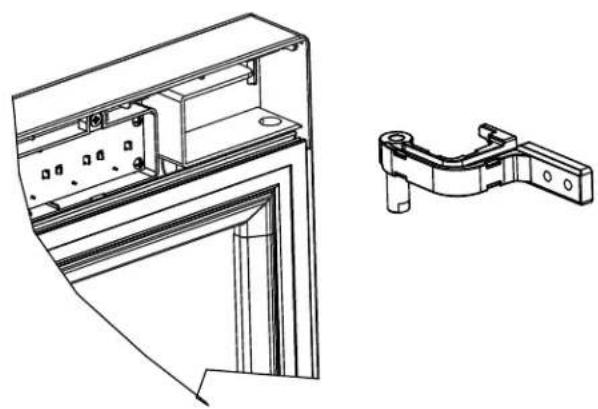
Line drawing of a hand gripping a mechanical clamp or bracket (no text or symbols)REMOVE THE DOOR CAM AND BRACKET
Remove the door cam and door bracket from the bottom of the door. Find the new door cam in the parts bag. Install the door bracket and the new door cam on the other side of the door.
natural_image
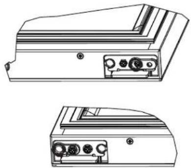
Technical line drawing of two electronic device rear panels with ports and connectors (no text or symbols)REMOVE BOTTOM HINGE ASSEMBLY
Tilt the cabinet (less than 45^ ) and remove the bottom hinge assembly (3 screws) and the other adjustable foot.
natural_image
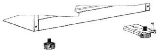
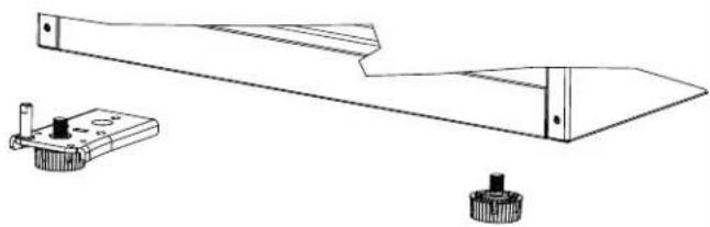
Technical line drawing of a mechanical assembly with two components (no text or symbols)REMOVE LOWER HINGE CAM AND HINGE SHAFT
Remove the lower hinge cam and hinge shaft. Install the shaft on the opposite side of the lower hinge. Take out the hinge cam from the parts bag and install it on the lower hinge shaft.
natural_image
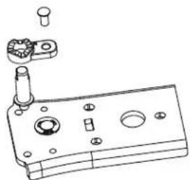
Technical line drawing of a mechanical component with mounting holes and a cylindrical part (no text or symbols)INSTALLATION INSTRUCTIONS
INSTALL LOWER HINGE ASSEMBLY
Install the lower hinge assembly on the left side of the cabinet. Lubricate the hinge cam. Install the other adjustable foot on the opposite side.
natural_image
Technical line drawing of a mechanical assembly with two components (no text or symbols)INSERT TOP HINGE
Insert the top hinge into the door.
natural_image
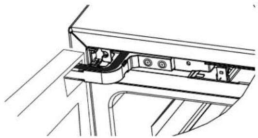
Technical line drawing of a mechanical bracket assembly (no text or symbols)ATTACH TOP HINGE
Attach the top hinge with two screws to the cabinet.
natural_image
Technical line drawing of a mechanical component with no visible text or symbolsROUTE THE DOOR WIRES
Route the door wires into the groove in the top hinge. Take the hinge cover from the parts bag and fasten it on the top hinge.
natural_image
Technical line drawing of a mechanical assembly with no visible text or symbolsINSTALL DOOR ON LOWER HINGE SHAFT
Install the door on the lower hinge shaft.
natural_image
Technical line drawing of a mechanical assembly with layered components and mounting base (no text or symbols)REPLACE DOOR TRIM
Snap in the door trim and push in the door gasket on the door.
natural_image
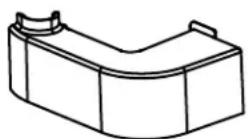
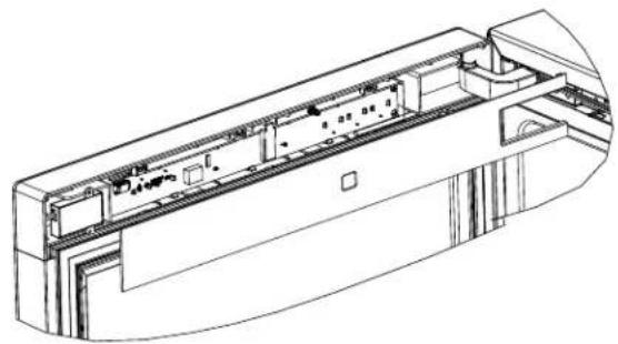
Technical line drawing of a mechanical or electronic component with internal compartments and mounting holes (no text or symbols)INSTALLATION INSTRUCTIONS
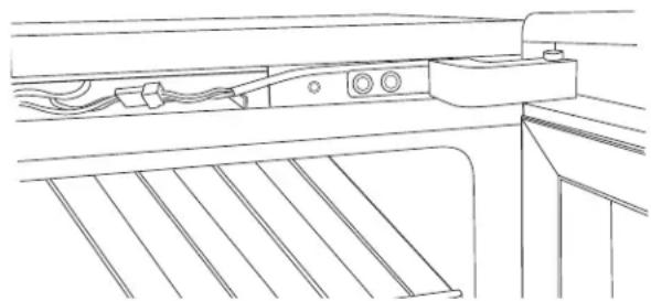
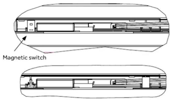
MOVE MAGNETIC SWITCH AND CONNECT DOOR WIRING
Move the magnetic switch to the right mounting slot, connect the door wiring and fasten the front trim of the cabinet. (Remove from the left side opening)
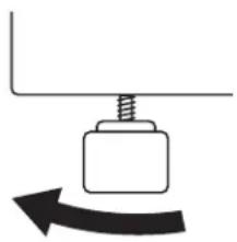
LEVEL
Adjustable legs at the front corners of the wine chiller should be set so the wine chiller is firmly positioned on the floor, with a 1/8" tilt to the back to help the door closure.
To adjust the leveling legs, turn the legs counterclockwise to raise the wine chiller, clockwise to lower it.
natural_image
Simple diagram of a screw pressing a block with an arrow indicating rotational motion (no text or symbols)To raise the appliance
CHECK DOOR FOR PROPER CLOSURE
Make sure the door is able to open and close in a good condition.
SET TEMPERATURE CONTROLS
- The temperature controls are preset. Refer to the Temperature Control section for more information. Allow 24 hours for temperature to stabilize.
CONNECT POWER
- Connect power cord plug to a properly grounded receptacle.
- Make sure power is on by opening the door to see if interior light turns on.
TROUBLE SHOOTING
Newer appliances sound different from older appliances. Modern appliances have more features and use newer technology.
HUMMM... WHOOSH...
■ The new high efficiency compressor may run faster and longer than your old appliance and you may hear a high-pitched hum or pulsating sound while it is operating.
■ Sometimes the appliance runs for an extended period, especially when the doors are opened frequently.
■ You may hear a whooshing sound when the doors close. This is due to pressure equalizing within the appliance.
WATER SOUNDS
■ The flow of refrigerant through the appliance cooling coils may make a gurgling noise like boiling water.
■ Closing the door may cause a gurgling sound due to pressure equalization.
CLICKS, POPS, CRACKS and CHIRPS
■ You may hear cracking or popping sounds when the appliance is first plugged in. This happens as the appliance cools to the correct temperature.
■ Expansion and contraction of cooling coils during and after defrost can cause a cracking or popping sound.
TROUBLE SHOOTING
| PROBLEM POSSIBLE | CAUSES WHAT TO DO | |
| Appliance does not operate | Appliance may be in defrost cycle. This is normal. Compressor does not operate for at least 40 minutes when in defrost cycle. | |
| Appliance is unplugged. Push the plug completely into the outlet. | ||
| Appliance is powered off. Power appliance back on. See “Power” in Temperature Control section. | ||
| The circuit breaker is tripped/ he fuse is blown. | Replace fuse or reset the breaker. | |
| GFI outlet is tripped. Reset outlet. | ||
| GFI outlet is not recommended. | ||
| Vibration or rattling (slight vibration is normal) | Appliance is on an uneven surface. | Adjust the leveling legs as shown in the Installation Instructions. |
| Motor operates for long periods or cycles on and off frequently | Normal when appliance is first plugged in. | Wait 24 hours for the appliance to completely cool down. |
| Often occurs when large amounts of wine or beverages are placed in the appliance. | This is normal. | |
| Door left open. Always make sure that the door is closed after opening. | ||
| Check to see if a bottle is holding door open. | ||
| Hot weather or frequent door openings. | This is normal. | |
| Temperature control set at the coldest setting. | Allow 24 hours for temperature to change. | |
| Compartment too warm | Normal when appliance is first plugged in. | Wait 24 hours for the appliance to completely cool down. |
| Often occurs when large amounts of wine or beverages are placed in the appliance. | This is normal. | |
| Temperature control not set cold enough. | See Temperature Control section. | |
| Warm weather or frequent door openings. | See Temperature Control section. | |
| Door left open. Always make sure that the door is closed after opening. | ||
| Check to see if a bottle is holding door open. | ||
| Appliance has odor Interior | needs cleaning. See Care and cleaning. | |
| Keep open box of baking soda in appliance; replace every 3 months. | ||
| Door not closing properly | Door gasket is sticking or folding over. | Apply petroleum jelly or paraffin wax to the face of the gasket. |
| The door is hitting an internal component inside the appliance. | Adjust internal components to prevent interference. | |
TROUBLE SHOOTING
| Problem Possible Causes | What To Do | |
| Moisture forms on outside of appliance | Not unusual during periods of high humidity. | If bothersome, wipe surface dry; otherwise, moisture will evaporate in time. |
| Door left open. Always make sure | that the door is closed after opening. | |
| Check to see if a bottle is holding door open. | ||
| Frost or moisture collects inside | Too frequent or too long door openings. | Appliance will dissipate moisture in time. If bothersome, wipe surface dry. |
| In humid weather, air carries moisture into appliance when door is opened. | Appliance will dissipate moisture in time. If bothersome, wipe surface dry. | |
| Temperature control set at coldest setting. | See Temperature Control section. | |
| Interior light does not operate | Appliance is unplugged. Push the plug completely into the outlet. | |
| The circuit breaker is tripped / the fuse is blown. | Replace fuse or reset the breaker. | |
| GFI outlet is tripped. Reset outlet | GFI outlet is not recommended. | |
| Hot air from bottom of appliance | Normal air flow cooling motor. | In the refrigeration process, it is normal for heat to be expelled in the area under the appliance. Some floor coverings are sensitive and will discolor at these safe and normal temperatures. |
| Appliance never shuts off Too | frequent or too long door openings. | This is normal. The appliance will cycle off after it reaches desired temperature. |
| Extreme environment temperatures | Normal operation in extreme temperatures. | |
NOTES
LIMITED WARRANTY
12 Months on Parts and Labor
For 12 months from the date of original retail purchase, GE Appliances will replace any part of the refrigerator that fails due to a defect in materials or workmanship. GE Appliances will choose, at its discretion, to replace or service the defective unit. Should GE Appliances decide to service the unit, GE Appliances will provide any part which fails due to a defect in materials or workmanship free of charge, along with any labor and related service costs to replace the defective part. During this period, should GE Appliances choose to replace the unit, it may do so by providing you with a certificate redeemable at a retailer for a replacement product.
Product must be accessible, without encumbrance and installed properly to receive warranty repair service.
NOTE: This warranty commences on the date the item was purchased, and the original purchase receipt must be presented to the authorized service representative before warranty repairs are rendered.
FOR WARRANTY SERVICE
For US Customers, all warranty service must be provided by our Factory Service Centers, or an authorized Customer Care technician. To schedule service, visit HaierAppliances.com. In Canada, visit HaierAppliances.ca.
Please have serial number and model number available when calling for service.
What is not covered by this warranty:
Service trips to your home to teach you how to use the product.
Improper installation, delivery or maintenance.
Failure of the product if it is abused, misused, or used for other than the intended purpose or used commercially.
Loss of food due to spoilage.
Damage caused after delivery.
Replacement of house fuses or resetting of circuit breakers.
Replacement of the light bulbs.
Damage to the product caused by accident, fire, floods or acts of God.
Incidental or consequential damage caused by possible defects with this appliance.
Product not accessible to provide required service.
Associated costs when GE Appliances chooses to issue the consumer a certificate as a form of product replacement.
Damage to finish, such as surface rust, tarnish, or small blemishes not reported within 48 hours of delivery.
Products which are not defective, broken, or which are working as described in the owner's manual.
EXCLUSION OF IMPLIED WARRANTIES - Your sole and exclusive remedy is product repair as provided in this Limited Warranty. Any implied warranties, including the implied warranties of merchantability or fitness for a particular purpose, are limited to one year or the shortest period allowed by law.
For US Customers: This warranty is extended to the original purchaser and any succeeding owner for products purchased for home use within the USA. If the product is located in an area where service by a GE Appliances Authorized Servicer is not available, you may be responsible for a trip charge or you may be required to bring the product to an Authorized GE Appliances Service location for service. In Alaska, the warranty excludes the cost of shipping or service calls to your home.
Some states do not allow the exclusion or limitation of incidental or consequential damages. This warranty gives you specific legal rights, and you may also have other rights which vary from state to state. To know what your legal rights are, consult your local or state consumer affairs office or your state's Attorney General.
Warrantor US:
GE Appliances, a Haier company
Louisville, KY 40225
For Customers in Canada: This warranty is extended to the original purchaser and any succeeding owner for products purchased in Canada for home use within Canada. In-home warranty service will be provided in areas where it is available and deemed reasonable by Mabe to provide.
Warrantor Canada:
MC Commercial, Inc., Burlington, Ontario, L7R 5B6
RECORD KEEPING
Thank you for purchasing this Haier product. This user manual will help you get the best performance from your new refrigerator.
For future reference, record the model number, serial number, and the date of purchase. The model/serial number plate is located on the inside wall of the refrigerator.
Staple your proof of purchase to this manual to aid in obtaining warranty service if needed.
Model number
Serial number
Date of purchase
Haier
Installation and User Manual
natural_image
Exterior view of a black and silver Holar air fryer cabinet (no text or symbols visible on the cabinet body)TABLE DES MATIÈRES
INFORMATION DE SÉCURITÉ 3
UTILISATION DE L'APPAREIL
natural_image
Technical line drawing of a multi-cylinder mechanical assembly with rollers and housing (no text or symbols)ENTREPOSAGE DE BOUTEILLES DE VIN SUR LA TABLETTE INFÉRIEURE
natural_image
Technical line drawing of a mechanical component with multiple cylindrical rollers arranged in a tray (no text or symbols)EMPILAGE DES BOUTEILLES DE VIN
natural_image
Technical line drawing of a multi-tiered storage unit with circular components (no text or symbols)NETTOYAGE DE L'EXTÉRIEUR DÉGIVRAGE AUTOMATIQUE
▲ AVERTISSEMENT AVERTISSEMENT
1" Minimum au Mur
natural_image
Exterior view of a modern black and silver refrigerator with front panel (no visible text or symbols)natural_image
Technical line drawing of a structural component with two parallel grooves and a notch (no text or symbols)INSTRUCTIONS POUR INVERSER LA PORTE
natural_image
Technical line drawing of a mechanical assembly with ladder and frame (no text or symbols)DÉBRANCHEMENT DU FIL DE RACCORDEMENT
natural_image
Line drawing of a kitchen counter with showerhead and side table (no text or symbols)INSTRUCTIONS D'INSTALLATION
SÉPARATION DU JOINT D'ÉTANCHÉITÉ DE PORTE SUPÉRIEUR
natural_image
Technical line drawing of a computer chassis with internal components and mounting brackets (no text or symbols)RETRAIT DE L'EXCENTRIQUE DE PORTE ET DU SUPPORT
natural_image
Technical line drawing of two electronic device rear panels with ports and connectors (no text or symbols)RETRAIT DES VIS DE LA CHARNIÈRE
natural_image
Technical line drawing of a mechanical component with no visible text or symbolsRETRAIT DE LA CHARNIÈRE INFÉRIEURE
natural_image
Technical line drawing of a mechanical component with flange and base mount (no text or symbols)INVERSION DE LA CHARNIÈRE SUPÉRIEURE
natural_image
Line drawing of a hand gripping a mechanical clamp or bracket (no text or symbols)RETRAIT DE L'EXCENTRIQUE DE CHARNIÈRE INFÉRIEURE ET DE SON AXE D'ARTICULATION
natural_image
Technical line drawing of a mechanical component with mounting holes and a cylindrical pin (no text or symbols)INSTRUCTIONS D'INSTALLATION
INSTALLATION DE LA CHARNIÈRE INFÉRIEURE
natural_image
Technical line drawing of a mechanical component with two views: top shows a blade and gear, bottom shows a base with a knob (no text or symbols)FIXATION DE LA CHARNIÈRE SUPÉRIEURE
natural_image
Technical line drawing of a mechanical component with no visible text or symbolsINSERTION DE LA CHARNIÈRE SUPÉRIEURE
natural_image
Technical line drawing of a mechanical bracket assembly (no text or symbols)ACHEMINEMENT DES CÂBLES DE PORTE
natural_image
Technical line drawing of a mechanical assembly with no visible text or symbolsINSTALLATION DE LA PORTE SUR L'AXE D'ARTICULATION DE CHARNIÈRE INFÉRIEURE
natural_image
Technical line drawing of a mechanical assembly with layered components (no text or symbols)RÉINSTALLATION DE LA GARNITURE DE PORTE
natural_image
Technical line drawing of a mechanical or electronic component with internal compartments and mounting holes (no text or symbols)INSTRUCTIONS D'INSTALLATION
DÉPLACEMENT DE L'INTERRUPTEUR MAGNÉTIQUE ET RACCORDEMENT DU CÂBLAGE DE PORTE
natural_image
Cross-sectional diagram of a ship's internal structure showing deck, hull, and deck layout (no text or labels)natural_image
Cross-sectional diagram of a mechanical or architectural structure with no visible text or symbolsNIVEAU
natural_image
Simple line drawing of a screw pressing a block with an arrow indicating rotational motion (no text or symbols)GE Appliances, a Haier company
Louisville, KY 40225
MC Commercial, Burlington, Ontario, L7R 5B6
DOCUMENTS À CONSERVER
Installation and User Manual
natural_image
Exterior view of a black and silver Holar refrigerator with front panel and side legs (no text or symbols visible)ÍNDICE
natural_image
Technical line drawing of a mechanical tray with multiple cylindrical rollers (no text or symbols)CARGA DE BOTELLAS DE VINO EN LA REPISA INFERIOR
natural_image
Technical line drawing of a mechanical assembly with multiple cylindrical components mounted on a base plate (no text or symbols)APILADO DE LAS BOTELLAS DE VINO
natural_image
Technical line drawing of a multi-tiered storage unit with circular components (no text or symbols)CUIDADO Y LIMPIEZA
Parte Superior - 2" (50.8 mm)
Parte Trasera - 2" (50.8 mm)
Laterales - 1" (25.4 mm)
natural_image
Exterior view of a modern black and silver refrigerator with front panel (no visible text or symbols)RETIRE EL EMBALAJE
natural_image
Technical line drawing of two parallel metal profiles with a central notch, showing no text or symbols.natural_image
Technical line drawing of a mechanical assembly or enclosure with ladder and frame (no text or symbols)natural_image
Technical line drawing of a mechanical assembly with no visible text or symbolsnatural_image
Technical line drawing of a mechanical or electronic component with no visible text or symbolsRETIRE LOS TORNILLOS DE LA BISAGRA SUPERIOR
natural_image
Technical line drawing of a mechanical assembly with no visible text or symbolsnatural_image
Line drawing of a hand gripping a mechanical clamp or bracket (no text or symbols)natural_image
Technical line drawing of a device rear panel with internal components and mounting holes (no text or symbols)RETIRE EL ENSAMBLE DE LA BISAGRA INFERIOR
natural_image
Technical line drawing of a mechanical component with base and mounting bracket (no text or symbols)RETIRE LA LEVA DE LA BISAGRA INFERIOR Y EL EJE DE LA BISAGRA
natural_image
Technical line drawing of a mechanical assembly with no visible text or symbolsnatural_image
Technical line drawing of a mechanical assembly with two components and a base (no text or symbols)ADHIERA LA BISAGRA SUPERIOR
natural_image
Technical line drawing of a mechanical assembly with no visible text or symbolsINSERTE LA BISAGRA SUPERIOR
natural_image
Technical line drawing of a mechanical bracket assembly (no text or symbols)natural_image
Technical line drawing of a mechanical assembly with no visible text or symbolsINSTALE LA PUERTA SOBRE EL EJE DE LA BISAGRA INFERIOR
natural_image
Technical line drawing of a mechanical assembly with no visible text or symbolsnatural_image
Technical line drawing of a mechanical or electronic component with internal compartments and mounting holes (no text or symbols)natural_image
Simple line drawing of a screw pressing a block with an arrow indicating rotational motion (no text or symbols)GE Appliances, a Haier company
Louisville, KY 40225
MC Commercial, Burlington, Ontario, L7R 5B6