HCR2250AES - Oven HAIER - Free user manual and instructions
Find the device manual for free HCR2250AES HAIER in PDF.

User questions about HCR2250AES HAIER
0 question about this device. Answer the ones you know or ask your own.
Ask a new question about this device
Download the instructions for your Oven in PDF format for free! Find your manual HCR2250AES - HAIER and take your electronic device back in hand. On this page are published all the documents necessary for the use of your device. HCR2250AES by HAIER.
USER MANUAL HCR2250AES HAIER
24" Electric Free-Standing Range
natural_image
Illustration of a stainless steel oven with six control knobs (no text or symbols)IMPORTANT: Save for local electrical inspector's use.
Tools and Parts....2
Location Requirements....3
Electrical Requirements 5
INSTALLATION INSTRUCTIONS....8
Step 1 - Unpack Range ....8
Step 2 - Install Anti-Tip Bracket ...... 9
Step 3 - Make Electrical Connection....10
Step 4 - Install Range....22
Step 5 - Complete Installation ....23
RANGE SAFETY
Your safety and the safety of others are very important.
We have provided many important safety messages in this manual and on your appliance. Always read and obey all safety messages.

text_image
Warning symbol with exclamation mark inside a triangleThis is the safety alert symbol.
This symbol alerts you to potential hazards that can kill or hurt you and others. All safety messages will follow the safety alert symbol and either the word "DANGER," "WARNING" or "CAUTION."
These words mean:
! DANGER
An imminently hazardous situation. You could be killed or seriously injured if you don't immediately follow instructions.
WARNING
A potentially hazardous situation which, if not avoided, could result in death or serious bodily injury.
CAUTION
A potentially hazardous situation which, if not avoided, may result in moderate or minor injury.
All safety messages will tell you what the potential hazard is, tell you how to reduce the chance of injury, and tell you what can happen if the instructions are not followed.
State of California Proposition 65 Warnings:
WARNING: This product contains one or more chemicals known to the State of California to cause cancer.
WARNING: This product contains one or more chemicals known to the State of California to cause birth defects or other reproductive harm.
WARNING

natural_image
Silhouette of a person pushing a large block on a horizontal line (no text or symbols)Tip Over Hazard
A child or adult can tip the range and be killed.
Connect anti-tip bracket to rear range foot.
Reconnect the anti-tip bracket, if the range is moved.
Failure to follow these instructions can result in death or serious burns to children and adults.
INSTALLATION REQUIREMENTS
TOOLS AND PARTS
Gather the required tools and parts before starting installation. Read and follow the instructions provided with any tools listed here.
TOOLS NEEDED
- Tape Measure
- Flat-Blade Screwdriver
• Phillips Screwdriver - Level
• Cordless Electric Drill - Hammer
- Wrench or Pliers
- Metal Saw
• Metal Snips or Large Wire Cutters
• ^15/16 " Combination Wrench
- ^3/8 " Nut Driver
- 1/4" Nut Driver
• 18 " (3.2 mm) Drill Bit (for wood floors)
- Marker or Pencil
- Masking Tape
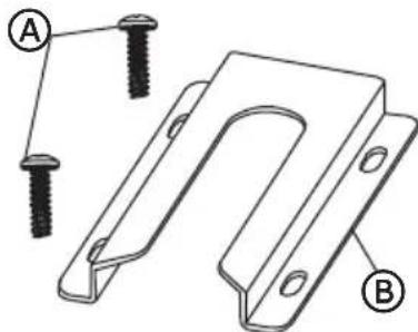
PARTS SUPPLIED
Check that all parts are included.
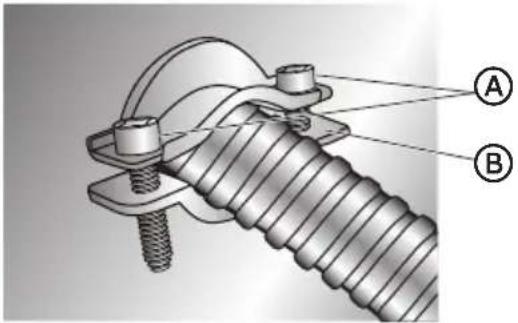
text_image
Technical diagram showing two labeled parts (A and B) of a U-shaped metal bracket with screw holes, likely illustrating a mechanical assembly or mounting design.A 16 x 1 ^5/8 " Screws (2)
B Anti-tip Bracket
NOTE: The Anti-tip bracket must be securely mounted to the subfloor. The thickness of flooring may require longer screws to anchor bracket to subfloor. Longer screws are available from your local hardware store.
PARTS NEEDED
If using a power supply cord:
- A UL listed power supply cord kit marked for use with ranges. The cord should be rated at 250 volts minimum, 40 amps or 50 amps that is marked for use with nominal 1^3/8 (3.5 cm) diameter connection opening and must end in ring terminals or open-end spade terminals with upturned ends.
• A UL listed strain relief.
If direct wiring:
• Flexible Metal Conduit
• UL Listed Conduit Connector
• 4-Wire or 3-Wire Electrical Cable (where local codes permit a 3-wire connection).
• UL Listed Wire Connectors
Check local codes. Check existing electrical supply. See the appropriate "Electrical Requirements" section. It is recommended that all electrical connections be made by a licensed, qualified electrical installer.
LOCATION REQUIREMENTS
VENTILATION
IMPORTANT: Observe all governing codes and ordinances.
- It is the installer's responsibility to comply with installation clearances specified on the model/serial rating plate. The model/serial rating plate is located on the left-hand side of the oven frame. Open oven door to view label. See label on back panel of range for additional element and oven power ratings.
TEMPERATURE
IMPORTANT: Some cabinet and building materials are not designed to withstand the heat produced by the oven for baking and self-cleaning. Check with your builder or cabinet supplier to make sure that the materials used will not discolor, delaminate or sustain other damage.
- Contact a qualified floor covering installer to check that the floor covering can withstand at least 200°F (93°C).
- Use an insulated pad or 14 " (0.64 cm) plywood under range if installing range over carpeting.
GENERAL
- The range should be located for convenient use in the kitchen.
- Recessed installations must provide complete enclosure of the sides and rear of the range.
- To eliminate the risk of burns or fire by reaching over heated surface units, cabinet storage space located above the surface units should be avoided. If cabinet storage is to be provided, the risk can be reduced by installing a range hood or microwave hood combination that projects horizontally a minimum of 5" (12.7 cm) beyond the bottom of the cabinets.
- All openings in the wall or floor where range is to be installed must be sealed.
- Do not seal the range to the side cabinets.
- Grounded electrical supply is required. See "Electrical Requirements" section.
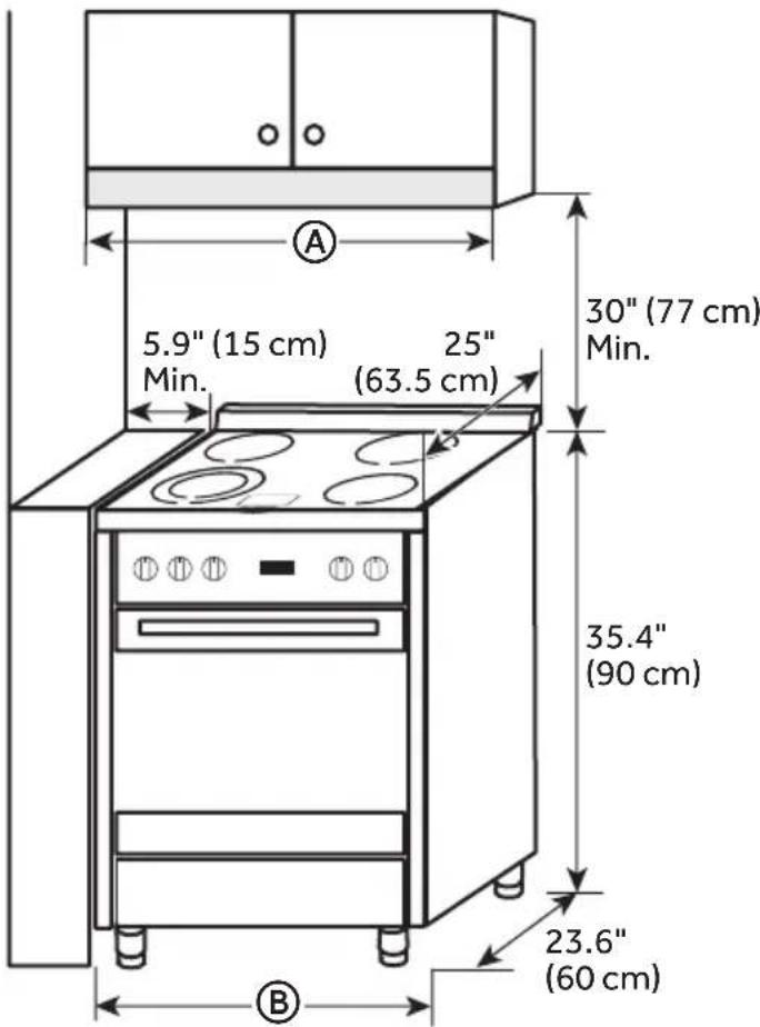
DIMENSIONS
Product/Clearance
text_image
5.9" (15 cm) Min. 25" (63.5 cm) 30" (77 cm) Min. 35.4" (90 cm) 23.6" (60 cm)| HCR2250AES HCR2250ACS | |
| A | 24" (61 cm) |
| B | 23.6" (60 cm) |
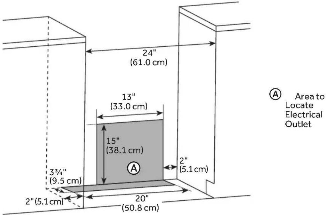
Power Supply
text_image
24" (61.0 cm) 13" (33.0 cm) 15" (38.1 cm) 3¾" (9.5 cm) 2" (5.1 cm) 20" (50.8 cm) 2" (5.1 cm) A Area to Locate Electrical OutletELECTRICAL REQUIREMENTS
IMPORTANT: Use a 3-wire, UL listed, 40-amp power supply cord (pigtail); or if local codes do not permit grounding through the neutral, use a 4-wire power supply cord rated at 250 volts, 40 amps and intended for use with ranges.
If codes permit and a separate ground wire is used, it is recommended that a qualified electrical installer determine that the ground path is adequate and wire gauge is in accordance with local codes.
To properly install your range, you must determine the type of electrical connection you will be using and follow the instructions provided for it here.
- Range must be connected to the proper electrical voltage and frequency as specified on the model/serial number rating plate. All models are dual rated, and designed to be connected to either 120/208 or 120/240V AC, 60Hz, 3-wire or 4-wire, single-phase power supply.
| Voltage and Frequency | Amps Minimum Circuit Required |
| 240V, 60 Hz 37.3A | |
| 208V, 60 Hz 32.4A |
- When a 4-wire, single phase 120/240 volt, 60 Hz., AC only electrical supply is available, a 40-amp maximum circuit protection is required (or, if specified on the model/serial rating plate, when a 4-wire, single phase 120/208 volt 60 Hz., AC only electrical supply is available, a 35-amp maximum circuit protection is required).
- For direct wire installations, install a suitable conduit box (not furnished). An appropriately sized, UL conduit connector must be used to correctly attach the conduit to the junction box.
IMPORTANT: Local Codes may vary; installation electrical connections and grounding must comply with all applicable local codes.
ELECTRICAL REQUIREMENTS - U.S.A. ONLY
Do not use an extension cord.
Be sure that the electrical connection and wire size are adequate and in conformance with the National Electrical Code, ANSI/ NFPA No. 70-latest edition and all local codes and ordinances.
A copy of the above code standards can be obtained from:
National Fire Protection Association
One Batterymarch Park
Quincy, MA 02269
WARNING

Electrical Shock Hazard
The electrical power to the oven branch circuit must be shut off while line connections are being made.
Do not use an extension cord with this appliance.
Electrical ground is required on this appliance. The free end of the green wire (the ground wire) must be connected to a suitable ground. This wire must remain grounded to the oven.
If cold water pipe is interrupted by plastic, non metallic gaskets, union connections or other insulating materials, DO NOT use for grounding.
DO NOT ground to a gas pipe.
DO NOT have a fuse in the NEUTRAL or GROUNDING circuit. A fuse in the NEUTRAL or GROUNDING circuit could result in an electrical shock.
Check with a qualified electrician if you are in doubt as to whether the appliance is properly grounded.
Failure to do so could result in death, fire or electric shock.
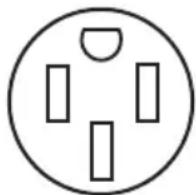
The range is not equipped with a power cord. The range can be fitted with a 3 or 4-wire NEMA 10-50 or 14-50 type SRDT or ST (as required) power cord rated at 250 volt AC minimum, 40 amp, with ring terminals or open-end spade terminals with upturned ends and marked for use with ranges.
- A UL listed strain relief must be attached to the range to hold the power cord.
- Do not use an aluminum wire receptacle with copper-wired power cord and plug (or vice versa). The proper wiring and receptacle is a copper-wired power cord with a copper-wired receptacle.
- The electrical outlet should be located so that the power cord is accessible when the range is in the installed position.
WARNING

Electrical Shock Hazard
Disconnect power before servicing.
Plug into a grounded outlet.
Do not use an extension cord.
Failure to do so can result in death, fire, or electrical shock.
Be sure that the electrical connection and wire size are adequate and in conformance with CSA Standard C22.1, Canadian Electrical Code, Part 1 - latest edition, and all local codes and ordinances.
A copy of the above code standards can be obtained from:
Canadian Standards Association
178 Rexdale Blvd.
Toronto, ON M9W 1R3 CANADA
- Check with a qualified electrical installer if you are not sure the range is properly grounded.
- This range is equipped with a CSA International Certified Power Cord intended to be plugged into a standard 14-50R wall receptacle. Be sure the wall receptacle is within reach of range's final location.
- Do not use an extension cord.
INSTALLATION INSTRUCTIONS
IMPORTANT: This appliance shall be installed only by authorized persons and in accordance with the manufacturer's installation instructions, local gas fitting regulations, municipal building codes, electrical wiring regulations, local water supply regulations.
STEP 1 - UNPACK RANGE
WARNING
Excessive Weight Hazard
Use two or more people to move and install range.
Failure to do so can result in back or other injury.
- Remove shipping materials, tape and film from the range. Keep cardboard bottom under range. Do not dispose of anything until the installation is complete.
- Remove oven racks and parts package from oven and shipping materials.
- To remove cardboard bottom, first take four cardboard corners from the carton. Stack one cardboard corner on top of another. Repeat with the other two corners. Place them lengthwise on the floor behind the range to support the range when it is laid on its back.
- Using two or more people, firmly grasp the range and gently lay it on its back on the cardboard corners.
- Remove cardboard bottom.
NOTES:
- The leveling legs can be adjusted while the range is on its back.
- To place range back up into a standing position, put a sheet of cardboard or hardboard on the floor in front of range to protect the flooring. Using two or more people, stand range back up onto the cardboard or hardboard.
WARNING

natural_image
Silhouette of a person pushing a large block on a horizontal line (no text or symbols)Tip Over Hazard
A child or adult can tip the range and be killed.
Connect anti-tip bracket to rear range foot.
Reconnect the anti-tip bracket, if the range is moved.
Failure to follow these instructions can result in death or serious burns to children and adults.
IMPORTANT:
- An anti-tip bracket kit is included with the range. Follow the instructions supplied with the anti-tip bracket.
- Do not completely remove the rear leveling leg. The anti-tip bracket uses a rear leveling leg to secure the range to the floor.
- The anti-tip bracket should be installed, so that it secures either the right or left rear leveling leg.
- After installing the leveling leg, note the distance from the side of the range to the center of the leveling leg. Mark this location on the floor.
- Attach the anti-tip bracket to the floor with 2 screws so that the rear leveling leg will be centered within the bracket once it is in its final position.
NOTE: Contact a qualified floor covering installer for the best procedure for drilling mounting holes through your type of floor covering.
STEP 3 - MAKE ELECTRICAL CONNECTION
After reading the requirements for each connection method, follow the electrical connection instructions specific to your situation.
Electrical Shock Hazard
Disconnect power before servicing.
Use a new 40 or 50 amp UL listed or CSA certified power supply cord.
Plug into a grounded outlet.
Do not use an extension cord.
Failure to do so can result in death, fire, or electrical shock.
3-WIRE CONNECTION: POWER SUPPLY CORD
IMPORTANT: Use this method only if local codes permit connecting chassis ground conductor to neutral wire of power supply cord.
- Disconnect power.
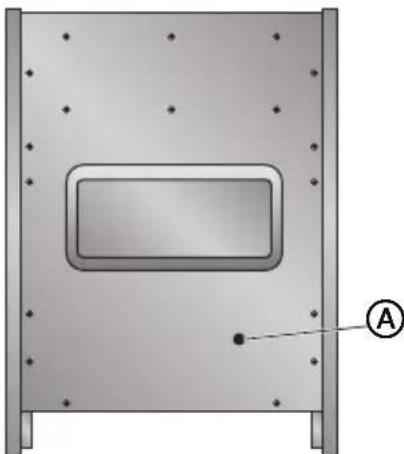
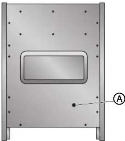
- Remove the screws fastening the back panel to the cabinet of the range. Lift off the back panel to access the electrical terminal block located in the bottom right-hand corner.
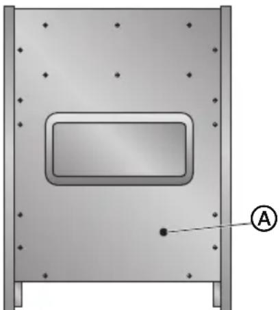
natural_image
Technical diagram of a mechanical component with mounting holes and a central rectangular cutout (no text or symbols)
Power Cord Opening
-
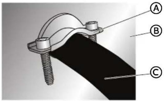
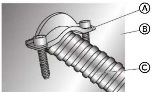
Install a UL listed strain relief (not provided) to the power cord opening in the back panel, and then completely tighten the nut.
-
With one person holding the back panel, thread the end of the power cord through the strain relief.
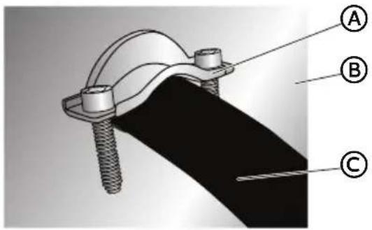
text_image
Technical diagram of a mechanical clamp or bracket assembly with labeled parts A, B, and C(A) UL Listed Strain Relief
B Back Panel
© Power Cord
NOTE: Allow enough slack to connect the wires to the terminal block.
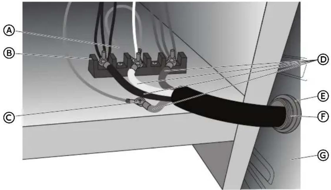
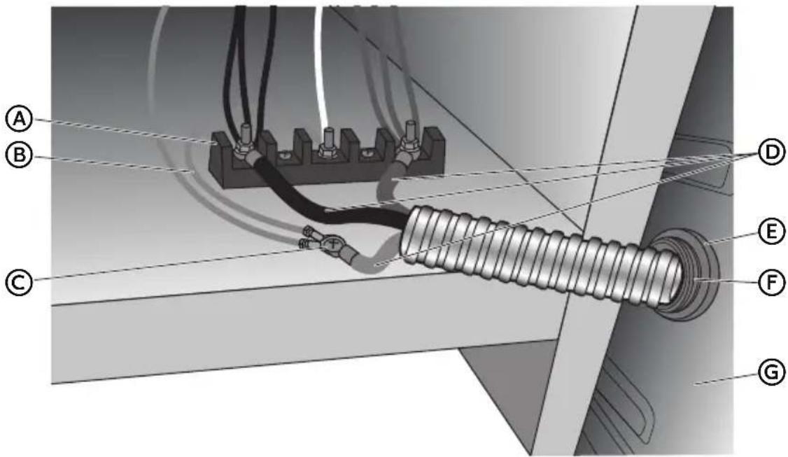
text_image
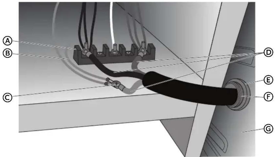
Technical diagram showing labeled components (A–G) of a cable or electrical connector assembly with wiring and connections.(A) Terminal Block
B Jumper Wire
© Ground Screw
D Power Cord Wires
E Strain Relief Nut
F UL Listed Strain Relief
G Back Panel
- Remove the ground screw. Place the green ground wire from the power cord on top of the green ground wire from the range, replace screw and tighten.
- Using 10-32 hex nuts, connect the red and black wires from the power cord to the outer posts of the terminal block with the corresponding red and black wires from the range.
- Tighten the hex nuts completely, and then verify the connection.
NOTE: For power supply cord replacement, use only a power cord rated at 250 volts minimum, 40- or 50-amps that is marked for use with nominal 1^3/8 (3.5 cm) diameter connection opening, with ring terminals and marked for use with ranges.
- Position the back panel against the back of the range, but do not fasten.
-
Gently, pull the excess power cord to the outside.
-
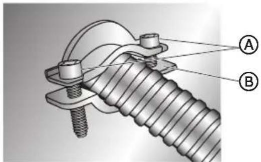
Position the lower part of the strain relief under the power cord and tighten the strain relief screws.
NOTE: Before tightening, make sure the strain relief is positioned over the cord and NOT the wires.
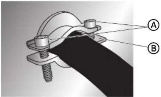
text_image
Technical diagram of a mechanical clamp or bracket assembly with labeled parts A and B
Strain Relief Screws

Lower Part of Strain Relief
- Replace the back panel screws, and then fully tighten the screws.
- Plug range into grounded outlet.
- Tuck excess power cord under the range.
4-WIRE CONNECTION: POWER SUPPLY CORD
IMPORTANT: Use this method for new branch-circuit installations (1996 NEC), mobile homes, recreational vehicles, or in an area where local codes prohibit grounding through the neutral.
- Disconnect power.
- Remove the screws fastening the back panel to the cabinet of the range. Lift off the back panel to access the electrical terminal block located in the bottom right-hand corner.
natural_image
3D diagram of a rectangular enclosure with mounting holes and a labeled point A (no text or symbols beyond label)
Power Cord Opening
-
Install a UL listed strain relief (not provided) to the power cord opening in the back panel, and then completely tighten the nut.
-
With one person holding the back panel, thread the end of the power cord through the strain relief.
text_image
Technical diagram of a mechanical clamp or bracket assembly with labeled parts A, B, and C(A) UL Listed Strain Relief
(B) Back Panel
© Power Cord
NOTE: Allow enough slack to connect the wires to the terminal block.
text_image
Technical diagram of a cable or electrical connector assembly with labeled parts A through GⒶ Jumper Wire
B Terminal Block
© Ground Screw
D Power Cord Wires
E Strain Relief Nut
(F) UL Listed Strain Relief
G Back Panel
-
Remove the green jumper wire from under the ground screw and replace with the green wire from the power cord and tighten ground screw.
-
Loop the green jumper wire removed from the ground screw back onto its end that is fastened to the center post of the terminal block.
-
Use 38 " (1.0 cm) nut driver to connect the neutral (white) wire to the center terminal block post with one of the 10-32 hex nuts.
-
Using 10-32 hex nuts, connect the red and black wires from the power cord to the outer posts of the terminal block with the corresponding red and black wires from the range.
-
Tighten the hex nuts completely, and then verify the connection.
NOTE: For power supply cord replacement, use only a power cord rated at 250 volts minimum, 40- or 50-amps that is marked for use with nominal 1^3/8 (3.5 cm) diameter connection opening, with ring terminals and marked for use with ranges.
-
Position the back panel against the back of the range, but do not fasten.
-
Gently, pull the excess power cord to the outside.
-
Position the lower part of the strain relief under the power cord and tighten the strain relief screws.
NOTE: Before tightening, make sure the strain relief is positioned over the cord and NOT the wires.
A
A
Strain Relief
B
Screws
B
Lower Part of
Strain Relief
-
Replace the back panel screws, and then fully tighten the screws.
-
Plug range into grounded outlet.
-
Tuck excess power cord under the range.
Electrical Shock Hazard
Plug into a grounded outlet.
Do not use an extension cord.
Failure to do so can result in death, fire, or electrical shock.
-
Plug into a standard 14-50R grounded wall receptacle.
-
Go to STEP 4 - INSTALL RANGE.
WARNING

Electrical Shock Hazard
Disconnect power before servicing.
Improper connection of aluminum house wiring and copper appliance leads can result in an electrical hazard or fire. If the home has aluminum wiring, only use connectors designed and UL listed for joining copper to aluminum and precisely follow the manufacturer's recommended procedure. Aluminum-to-Copper connections must conform with local codes.
Use 8 gauge copper or aluminum wire.
Electrically ground range.
Failure to do so can result in death, fire or electrical shock.
Be sure your appliance is properly installed and grounded by a qualified technician. Ask your dealer to recommend a qualified technician or an authorized repair service.
• A circuit breaker is recommended.
- The range can be connected directly to the circuit breaker box (or fused disconnect) through flexible or nonmetallic sheathed, copper or aluminum cable.
- Allow at least 6 ft (1.8 m) of slack in the line so that the range can be moved if servicing is ever necessary.
- A UL listed conduit connector must be provided at each end of the power supply cable (at the range and at the junction box).
- Wire sizes and connections must conform with the rating of the range.
- The tech sheet and wiring diagram are included with the range.
This appliance is manufactured with a green GROUND wire connected to the range chassis. After making sure that the power has been turned off, connect the flexible conduit from the range to the junction box using a UL listed conduit connector. The Grounded Neutral and Ungrounded Neutral Graphics on the following pages and the instructions provided, present the most common way of connecting the range. Your local codes and ordinances, of course, take precedence over these instructions. Complete electrical connections according to local codes and ordinances.
3-WIRE CONNECTION (GROUNDED NEUTRAL)
WARNING

Electrical Shock Hazard
Grounding through the neutral conductor is prohibited for new branch-circuit installations (1996 NEC); mobile homes; and recreational vehicles, or in an area where local codes prohibit grounding through the neutral conductor. For installations where grounding through the neutral conductor is prohibited, see the Ungrounded Neutral graphic.
Use grounding terminal or lead to ground unit.
Connect neutral terminal or lead to branch circuit neutral in usual manner.
Failure to do so could result in death, fire or electric shock.
Connect to the House Electrical Supply
IMPORTANT: Use the 3-wire cable from home power supply where local codes permit a 3-wire connection.
- Disconnect power.
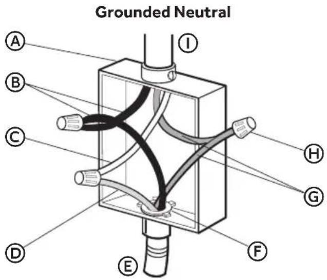
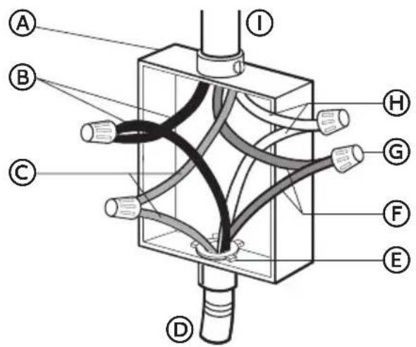
text_image
Grounded Neutral A B C D E F G H IⒶ Junction Box
B Black Wires
© Neutral (White) Wire
(D) Ground (Green or Bare) Wire
E Cable from Oven
F UL Listed Conduit Connector
G Red Wires
H UL Listed Wire Connectors
① House Electrical Supply
- Connect the 2 black wires Ⓑ together using a UL listed wire connector.
- Connect the neutral (white) wire © and the ground (green or bare) wire Ⓓ (of the oven cable) using a UL listed wire connector.
- Connect the 2 red wires Ⓖ together using a UL listed wire connector.
- Install junction box cover.
Connect to the Range
- Feed the electric cable wires through the flexible metal conduit.
NOTE: Allow enough slack to easily attach the wires to the terminal block.
- Remove the screws fastening the back panel to the cabinet of the range. Lift off the back panel to access the electrical terminal block located in the bottom right-hand corner.
natural_image
Technical diagram of a mechanical component with mounting holes and a central rectangular cutout (no text or symbols)A
Conduit Opening
- Install a UL listed strain relief (not provided) to the conduit opening in the back panel, and then completely tighten the nut.
- With one person holding the back panel, thread the end of the conduit through the strain relief.
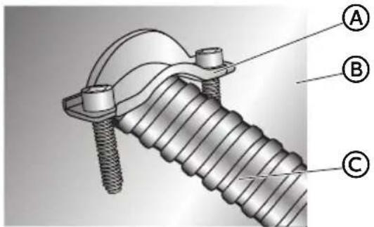
text_image
Technical diagram of a threaded fastener with labeled parts A, B, and CA
UL Listed Strain Relief
B
Back Panel
©
Conduit
NOTE: Allow enough slack to connect the wires to the terminal block.
text_image
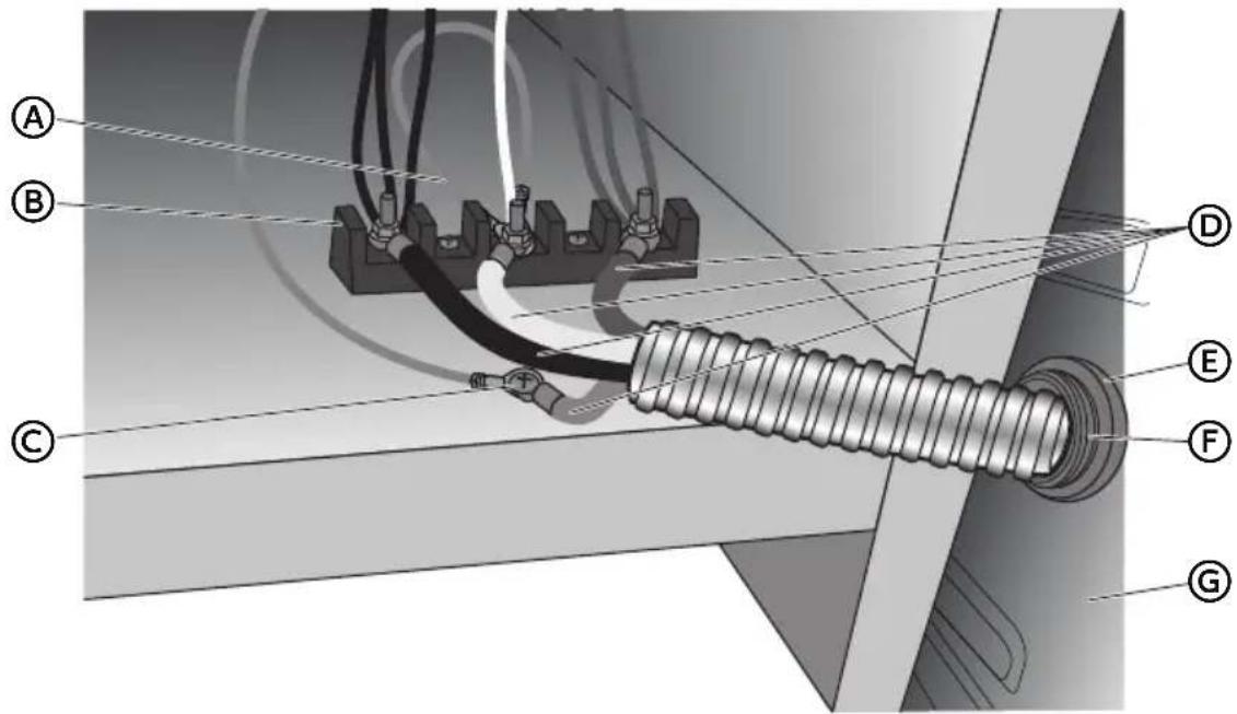
Technical diagram of a mechanical or electrical assembly with labeled components A through G, showing connections and wiring.A
Terminal Block
E
Strain Relief Nut
B
Jumper Wire
F
UL Listed Strain Relief
©
Ground Screw
G
Back Panel
D
Power Cord Wires
- Remove the ground screw. Place the green ground wire from the conduit on top of the green ground wire from the range, replace screw and tighten.
- Using 10-32 hex nuts, connect the red and black wires from the conduit to the outer posts of the terminal block with the corresponding red and black wires from the range.
- Tighten the hex nuts completely, and then verify the connection.
- Position the back panel against the back of the range, but do not fasten.
- Gently, pull the excess conduit to the outside.
- Position the lower part of the strain relief under the conduit and tighten the strain relief screws.
NOTE: Before tightening, make sure the strain relief is positioned over the conduit and NOT the wires.
text_image
Technical diagram of a mechanical assembly with labeled parts A and B, showing threaded fastener and mounting bracket.A
Strain Relief Screws
B
Lower Part of Strain Relief
- Replace the back panel screws, and then fully tighten the screws.
- Tuck excess conduit under the range.
4-WIRE CONNECTION (UNGROUNDED NEUTRAL)
Connect to the House Electrical Supply - U.S.A. Only
IMPORTANT: Use the 4-wire cable from home power supply in the U.S. where local codes do not allow grounding through neutral, new branch circuit installations (1996 NEC), mobile homes and recreational vehicles, new construction and in Canada.
- Disconnect power.
Ungrounded Neutral
text_image
A B C D I H G F EⒶ Junction Box
B Black Wires
© Red Wires
(D) Cable from Oven
E UL listed or CSA Approved Conduit Connector
(F) Ground (Green or Bare) Wires
G UL Listed Wire Connector
H Neutral (White) Wires
① House Electrical Supply
-
Connect the 2 black wires Ⓑ together using a UL listed wire connector.
-
Connect the 2 red wires © together using a UL listed wire connector.
-
Connect the 2 neutral (white) wires Ⓗ together using a UL listed wire connector.
-
Connect the ground (green or bare) wire ⑤ from the oven cable to the ground (green or bare) wire (in the junction box) using a UL listed wire connector.
-
Install junction box cover.
Connect to the Range
- Feed the electric cable wires through the flexible metal conduit.
NOTE: Allow enough slack to easily attach the wires to the terminal block.
- Remove the screws fastening the back panel to the cabinet of the range. Lift off the back panel to access the electrical terminal block located in the bottom right-hand corner.
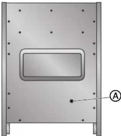
natural_image
3D diagram of a rectangular enclosure with mounting holes and a labeled point A (no text or symbols beyond label)
Conduit Opening
-
Install a UL listed strain relief (not provided) to the conduit opening in the back panel, and then completely tighten the nut.
-
With one person holding the back panel, thread the end of the conduit through the strain relief.
text_image
Technical diagram of a threaded fastener with labeled parts A, B, and C
UL Listed Strain Relief

Back Panel

Conduit
NOTE: Allow enough slack to connect the wires to the terminal block.
text_image
Technical diagram of a cable or insulator assembly with labeled components A through GA
Jumper Wire
E
Strain Relief Nut
B
Terminal Block
F
UL Listed Strain Relief
©
Ground Screw
G
Back Panel
D
Power Cord Wires
- Remove the green jumper wire from under the ground screw and replace with the green wire from the conduit and tighten ground screw.
- Loop the green jumper wire removed from the ground screw back onto its end that is fastened to the center post of the terminal block.
- Use 38 " (1.0 cm) nut driver to connect the neutral (white) wire to the center terminal block post with one of the 10-32 hex nuts.
- Using 10-32 hex nuts, connect the red and black wires from the conduit to the outer posts of the terminal block with the corresponding red and black wires from the range.
- Tighten the hex nuts completely, and then verify the connection.
- Position the back panel against the back of the range, but do not fasten.
-
Gently, pull the excess conduit to the outside.
-
Position the lower part of the strain relief under the conduit and tighten the strain relief screws.
NOTE: Before tightening, make sure the strain relief is positioned over the conduit and NOT the wires.
text_image
Technical diagram of a threaded fastener assembly with labeled parts A and BA
Strain Relief Screws
B
Lower Part of Strain Relief
- Replace the back panel screws, and then fully tighten the screws.
- Tuck excess conduit under the range.
STEP 4 - INSTALL RANGE
IMPORTANT: If the range is moved to adjust the leveling legs, make sure when you move the range back into its final location that the anti-tip bracket is engaged by repeating steps 1 through 9.
- Slide range into final location, making sure rear leveling leg slides into anti-tip bracket. Leave a 1" (2.5 cm) gap between the back of the range and the back wall.
- Place the outside of your foot against the bottom front to keep the range from moving, and then grasp the back of the range, as shown.

natural_image
Line drawing of a person leaning against the side of a refrigerator (no text or symbols)- Slowly attempt to tilt the range forward.
If you encounter immediate resistance, the range foot is engaged in the anti-tip bracket. Go to Step 8.
- If the rear of the range lifts more than 12 " (1.3 cm) off the floor without resistance, stop tilting the range and lower it gently back to the floor. The range foot is not engaged in the anti-tip bracket.
IMPORTANT: If there is a snapping or popping sound when lifting the range, the range may not be fully engaged in the bracket. Check to see if there are obstructions keeping the range from sliding to the wall or keeping the range foot from sliding into the bracket. Verify that the bracket is held securely in place by the mounting screws.
-
Slide the range forward, and verify that the anti-tip bracket is securely attached to the floor or wall.
-
Slide range back so the rear range foot is inserted into the slot of the anti-tip bracket.
-
Repeat steps 1 through 3 to ensure that the range foot is engaged in the anti-tip bracket.
If the rear of the range lifts more than 12 " (1.3 cm) off the floor without resistance, the anti-tip bracket may not be installed correctly. Do not operate the range without anti-tip bracket installed and engaged.
- Move the range into its final location. Check that the range is level by placing a level on the oven bottom.
NOTE: The range must be level for optimum cooking and baking performance.
- If needed, use a wrench to adjust the height of the leveling legs until the range is level from side to side and from front to back.
STEP 5 - COMPLETE INSTALLATION
-
Reconnect power at the circuit breaker or fuse box.
-
Turn on each element to check that it is heating correctly.
-
Turn on the oven to check that it is heating correctly.
NOTE: When the range has been on for 5 minutes, check for heat. If range is cold, turn off the range and contact a qualified technician.
- Check that the indicator lights on the control panel, and the interior oven lights illuminate correctly.
If the range does not operate correctly, check the following:
• Household fuse is intact and tight; or circuit breaker has not tripped.
- Range is plugged into a grounded outlet.
• Electrical supply is connected.
Contact a qualified electrician to verify the electrical supply.
TABLE DES MATIÈRES
SÉCURITÉ DE LA CUISINIÈRE 25
EXIGENCES D'INSTALLATION....26
text_image
Warning symbol with exclamation mark inside a triangle, commonly used to indicate caution or hazard.natural_image
Silhouette of a person pushing a large block on a horizontal line (no text or symbols)text_image
Technical diagram showing two labeled components (A and B) of a U-shaped metal bracket with screw holes and mounting holes.A
Vis de 16 x 1 ^5/8 " (2)
B
La bride antibasculement
text_image
5,9" (15 cm) Min. 25" (63,5 cm) 30" (77 cm) Min. 35,4" (90 cm) 23,6" (60 cm)| HCR2250AES HCR2250ACS | |
| A | 24" (61 cm) |
| B | 23,6" (60 cm) |
National Fire Protection Association
One Batterymarch Park
Quincy, MA 02269
AVERTISSEMENT

Canadian Standards Association
178 Rexdale Blvd.
Toronto, ON M9W 1R3 CANADA
natural_image
Silhouette of a person pushing a large block on a flat surface (no text or symbols)natural_image
Diagram of a rectangular enclosure with a central rectangular opening and mounting holes, labeled with point A (no text or symbols beyond label)
text_image
Technical diagram of a mechanical clamp or bracket assembly with labeled parts A, B, and Ctext_image
Technical diagram of electrical cable connections with labeled components A through GⒶ Bornier
B Cavalier
text_image
Technical diagram of a mechanical clamp or bracket assembly with labeled parts A and BA
Vis du serre-câble
B
natural_image
Technical diagram of a mechanical component with mounting holes and a central rectangular cutout (no text or symbols)A
text_image
Technical diagram of a mechanical clamp or bracket assembly with labeled parts A, B, and CA
text_image
A B C D E F Ga Cavalier
b Bornier
text_image
Technical diagram of a mechanical clamp or bracket assembly with labeled parts A and B
Vis du serre-câble

text_image
Technical diagram of a mechanical or electrical component with labeled parts A through I, showing internal connections and structural features.natural_image
Technical diagram of a mechanical component with mounting holes and a central rectangular cutout (no text or symbols)A
text_image
Technical diagram of a threaded fastener with labeled parts A, B, and CA
text_image
Technical diagram of a mechanical assembly with labeled components A through G, showing connections and wiring.Ⓐ Bornier
B Cavalier
text_image
Technical diagram of a mechanical assembly with labeled parts A and Btext_image
A B C D I H G F Enatural_image
Technical diagram of a mechanical component with mounting holes and a central rectangular cutout (no text or symbols)A
text_image
Technical diagram of a threaded fastener assembly with labeled parts A, B, and CA
text_image
Technical diagram of a cable or insulator assembly with labeled components A through GA
Cavalier
E
text_image
Technical diagram of a mechanical assembly with labeled parts A and B, showing threaded fastener and mounting bracket.A
Vis du serre-câble
B
natural_image
Line drawing of a person leaning against the side of a refrigerator (no text or symbols)text_image
Warning sign with exclamation mark inside a triangle, commonly used to indicate caution or hazard.natural_image
Silhouette of a person pushing a large block on a flat surface (no text or symbols)Peligro de Vuelco
text_image
5,9" (15 cm) Min. 25" (63,5 cm) 30" (77 cm) Min. 35,4" (90 cm) 23,6" (60 cm)| HCR2250AES HCR2250ACS | |
| A | 24" (61 cm) |
| B | 23,6" (60 cm) |
National Fire Protection Association
One Batterymarch Park
Quincy, MA 02269
ADVERTENCIA

Canadian Standards Association 178 Rexdale Blvd.
Toronto, ON M9W 1R3 CANADA
natural_image
Silhouette of a person pushing a large block on a horizontal line (no text or symbols)Peligro de Vuelco
natural_image
Technical diagram of a mechanical component with mounting holes and a central rectangular cutout (no text or symbols)
text_image
Technical diagram of a mechanical clamp or bracket assembly with labeled parts A and BA
natural_image
Technical diagram of a mechanical component with mounting holes and a central rectangular cavity, labeled with point A (no text or symbols beyond label)A
text_image
Technical diagram of a mechanical clamp or bracket assembly with labeled parts A, B, and Ctext_image
Technical diagram of a cable or electrical connector with labeled parts A through GⒶ Hilo de puente
E Tuerca del protector de cables
B Bloque de terminales
text_image
Technical diagram of a mechanical clamp or bracket assembly with labeled parts A and B
natural_image
Technical diagram of a mechanical component with mounting holes and a central rectangular cutout (no text or symbols)A
text_image
Technical diagram of a threaded fastener with labeled parts A, B, and CA
text_image
Technical diagram of an electrical insulator assembly with labeled components A through Gnatural_image
Technical diagram of a mechanical component with mounting holes and a central rectangular cutout (no text or symbols)A
text_image
Technical diagram of a threaded fastener with labeled parts A, B, and CA
natural_image
Line drawing of a person leaning against the side of a refrigerator (no text or symbols)If you have a problem with this product, please contact the
"Haier Customer Satisfaction Center" at
1-877-337-3639.
DATED PROOF OF PURCHASE, MODEL #, AND SERIAL #
REQUIRED FOR WARRANTY SERVICE
IMPORTANT
Issued: March 2016 Printed in China Part # 0570000768 REV B