
HCR6250AGS - Cooker HAIER - Free user manual and instructions
Find the device manual for free HCR6250AGS HAIER in PDF.

| Product Type | Freestanding Gas Range |
| Brand | Haier |
| Model | HCR6250AGS |
| Width | 60 cm (23 2/5 in) |
| Depth (with handle) | 64.28 cm (25 15/16 in) |
| Overall Height | 95.5 cm (37 5/8 in) |
| Height to Cooking Surface | 91 cm (36 in) |
| Gas Supply | Natural Gas (convertible to LPG/propane) |
| Electrical Supply | 120 V, 60 Hz, 15 A, 3-prong grounded outlet |
| Number of Burners | 4 (Auxiliary, Semi-Rapid, Triple Ring, Rapid) |
| Heat Output - Front Right Burner (Auxiliary) | 5 000 BTU/h |
| Heat Output - Rear Left Burner (Semi-Rapid) | 6 859 BTU/h |
| Heat Output - Front Left Burner (Triple Ring) | 17 357 BTU/h (NG) / 15 000 BTU/h (LPG) |
| Heat Output - Rear Right Burner (Rapid) | 6 859 BTU/h |
| Ignition System | Electronic (without pilot light) |
| Anti-Tip Bracket | Included |
| Gas Conversion | Possible (natural gas to LPG with included kit) |
| Backguard | Included |
| Gas Connection | Rigid pipe 3/4 in or CSA approved flexible connector |
| Safety | Manual gas shutoff, leak detection recommended |
| Cleaning | Manual cleaning of burners and surfaces |
Frequently Asked Questions - HCR6250AGS HAIER
User questions about HCR6250AGS HAIER
0 question about this device. Answer the ones you know or ask your own.
Ask a new question about this device
Download the instructions for your Cooker in PDF format for free! Find your manual HCR6250AGS - HAIER and take your electronic device back in hand. On this page are published all the documents necessary for the use of your device. HCR6250AGS by HAIER.
USER MANUAL HCR6250AGS HAIER
24" and 36" Gas Free-Standing Range
natural_image
Illustration of a Haier oven with control knobs and door (no text or symbols on the main body)IMPORTANT: Save for local electrical inspector's use.
Tools and Parts....4
Location Requirements....6
Electrical Requirements 9
Gas Supply Requirements 10
INSTALLATION INSTRUCTIONS....13
Step 1 - Unpack Range ....13
Step 2 - Install Backsplash....13
Step 3 - Install Anti-tip Bracket....14
Step 4 - Make Gas Connection....16
Step 5 - Make Electrical Connection....18
Step 6 - Install Range....18
Step 7 - Level the Range (if needed) ...... 19
Step 8 - Check Operation of Electronic Ignition System....20
GAS CONVERSION....21
Step 1 - Adjust the Regulator....24
Step 2 - Change Top Burner Orifices....25
Step 3 - Adjust Burner Flames ...... 26
Step 4 - Testing Flame Stability....27
Step 5 - Flame Re-Check....27
Step 6 - Change Oven Burner Orifices (HCR2250AGS)....27
Step 6 - Change Oven Burner Orifices (HCR6250AGS)....31
Your safety and the safety of others are very important.
We have provided many important safety messages in this manual and on your appliance. Always read and obey all safety messages.

This is the safety alert symbol.
This symbol alerts you to potential hazards that can kill or hurt you and others. All safety messages will follow the safety alert symbol and either the word "DANGER," "WARNING" or "CAUTION."
These words mean:
! DANGER
An imminently hazardous situation. You could be killed or seriously injured if you don't immediately follow instructions.
WARNING
A potentially hazardous situation which, if not avoided, could result in death or serious bodily injury.
CAUTION
A potentially hazardous situation which, if not avoided, may result in moderate or minor injury.
All safety messages will tell you what the potential hazard is, tell you how to reduce the chance of injury, and tell you what can happen if the instructions are not followed.
WARNING

Fire Hazard
If the information in this manual is not followed exactly, a fire or explosion may result causing property damage, personal injury or death.
- Do not store or use gasoline or other flammable vapors and liquids in the vicinity of this or any other appliance.
-
WHAT TO DO IF YOU SMELL GAS
-
Do not try to light any appliance.
- Do not touch any electrical switch.
- Do not use any phone in your building.
- Clear the room, building, or area of all occupants.
- Immediately call your gas supplier from a neighbor's phone. Follow the gas supplier's instructions.
- If you cannot reach your gas supplier, call the fire department.
- Installation and service must be performed by a qualified installer, service agency or the gas supplier.
WARNING: Gas leaks cannot always be detected by smell.
Gas suppliers recommend that you use a gas detector approved by UL or CSA.
For more information, contact your gas supplier.
If a gas leak is detected, follow the “What to do if you smell gas” instructions.
In the State of Massachusetts, the following installation instructions apply:
- Installations and repairs must be performed by a qualified or licensed contractor, plumber, or gasfitter qualified or licensed by the State of Massachusetts.
- If using a ball valve, it shall be a T-handle type.
- A flexible gas connector, when used, must not exceed 3 feet.
State of California Proposition 65 Warnings:
WARNING: This product contains one or more chemicals known to the State of California to cause cancer.
WARNING: This product contains one or more chemicals known to the State of California to cause birth defects or other reproductive harm.
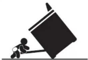
WARNING
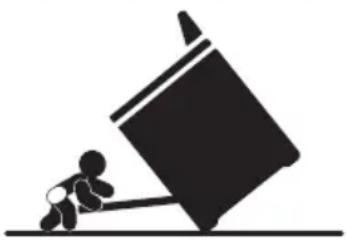
natural_image
Silhouette of a person pushing a large block on a horizontal line (no text or symbols)Tip Over Hazard
A child or adult can tip the range and be killed.
Connect anti-tip bracket to rear range foot.
Reconnect the anti-tip bracket, if the range is moved.
Failure to follow these instructions can result in death or serious burns to children and adults.
INSTALLATION REQUIREMENTS
TOOLS AND PARTS
Gather the required tools and parts before starting installation. Read and follow the instructions provided with any tools listed here.
TOOLS NEEDED
- Tape measure
- Flat-blade screwdriver
• Phillips screwdriver - Level
- Cordless electric drill
- Hammer
- Wrench or pliers
-
Pipe wrench
• 10" Adjustable Wrenches (2) -
3/8'' nut driver
- 1 14 " nut driver
• 18 " (3.2 mm) drill bit (for wood floors) - Marker or pencil
- Masking tape
- Pipe-joint compound resistant to LP gas
- 316 " carbide-tipped masonry drill bit (for concrete/ceramic floors)
• Noncorrosive leak-detection solution
For LP/Natural Gas Conversions
- 1/2'' Combination wrench
• 7 mm combination wrench
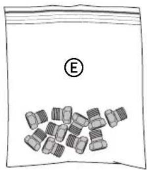
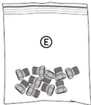
PARTS SUPPLIED
Check that all parts are included.
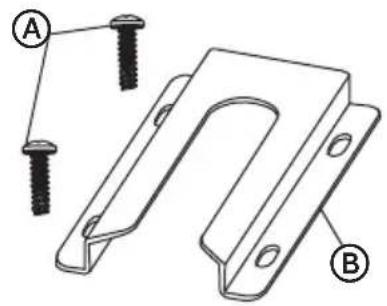
A 16 x 1 ^5/8 " Screws (2)
B Anti-tip Bracket
© Regulator
(D) Gas Pipe Adapter with Washer
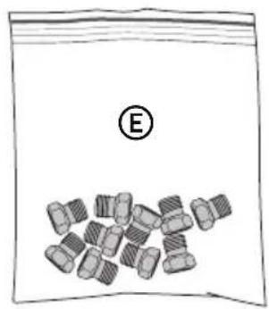
natural_image
Illustration of a bag with a pile of bolts and a labeled 'E' (no text or symbols on the bag itself)E LP/Natural Gas Conversion Kit
NOTE: The Anti-tip bracket must be securely mounted to the subfloor. Depending on the thickness of the flooring, longer screws may be required to anchor the anti-tip bracket to the subfloor. Longer screws are available from your local hardware store.
PARTS NEEDED
Check local codes and consult gas supplier. Check existing gas supply and electrical supply. See "Electrical Requirements" and "Gas Supply Requirements" sections.
• Gas Supply Line Kit (Supply line and 2 adapters)
natural_image
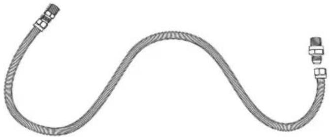
Schematic illustration of a flexible hose with connectors (no text or symbols)LOCATION REQUIREMENTS
VENTILATION
IMPORTANT: Observe all governing codes and ordinances. Do not obstruct flow of combustion and ventilation air.
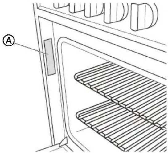
- It is the installer's responsibility to comply with installation clearances specified on the model/serial rating plate. The model/serial rating plate is located on the left-hand side of the oven frame. Open oven door to view label. See label on back panel of range for additional element and oven power ratings.
natural_image
Technical line drawing of a door with a grating and a labeled component (A), showing no text or symbols beyond the label.A
Rating Plate
TEMPERATURE
IMPORTANT: This oven has been designed in accordance with the requirements of UL and CSA International and complies with the maximum allowable wood cabinet temperatures of 194F (90°C).
- Some cabinet and building materials are not designed to withstand the heat produced by the oven for baking and self-cleaning. Check with your builder or cabinet supplier to make sure that the materials used will not discolor, delaminate or sustain other damage.
- Contact a qualified floor covering installer to check that the floor covering can withstand at least 200°F (93°C).
- Use an insulated pad or 14 " (0.64 cm) plywood under range if installing range over carpeting.
GENERAL
- The range should be located for convenient use in the kitchen.
- Recessed installations must provide complete enclosure of the sides and rear of the range.
- To eliminate the risk of burns or fire by reaching over heated surface units, cabinet storage space located above the surface units should be avoided. If cabinet storage is to be provided, the risk can be reduced by installing a range hood or microwave hood combination that projects horizontally a minimum of 5" (12.7 cm) beyond the bottom of the cabinets.
- All openings in the wall or floor where range is to be installed must be sealed.
- Do not seal the range to the side cabinets.
- Grounded electrical supply is required. See "Electrical Requirements" section.
- Proper gas supply connection must be available. See "Gas Supply Requirements" section.
DIMENSIONS
Product and Opening
Opening dimensions shown are for 25" (64.0 cm) countertop depth, 4" (61.0 cm) base cabinet depth and 36" (91.4 cm) countertop height.
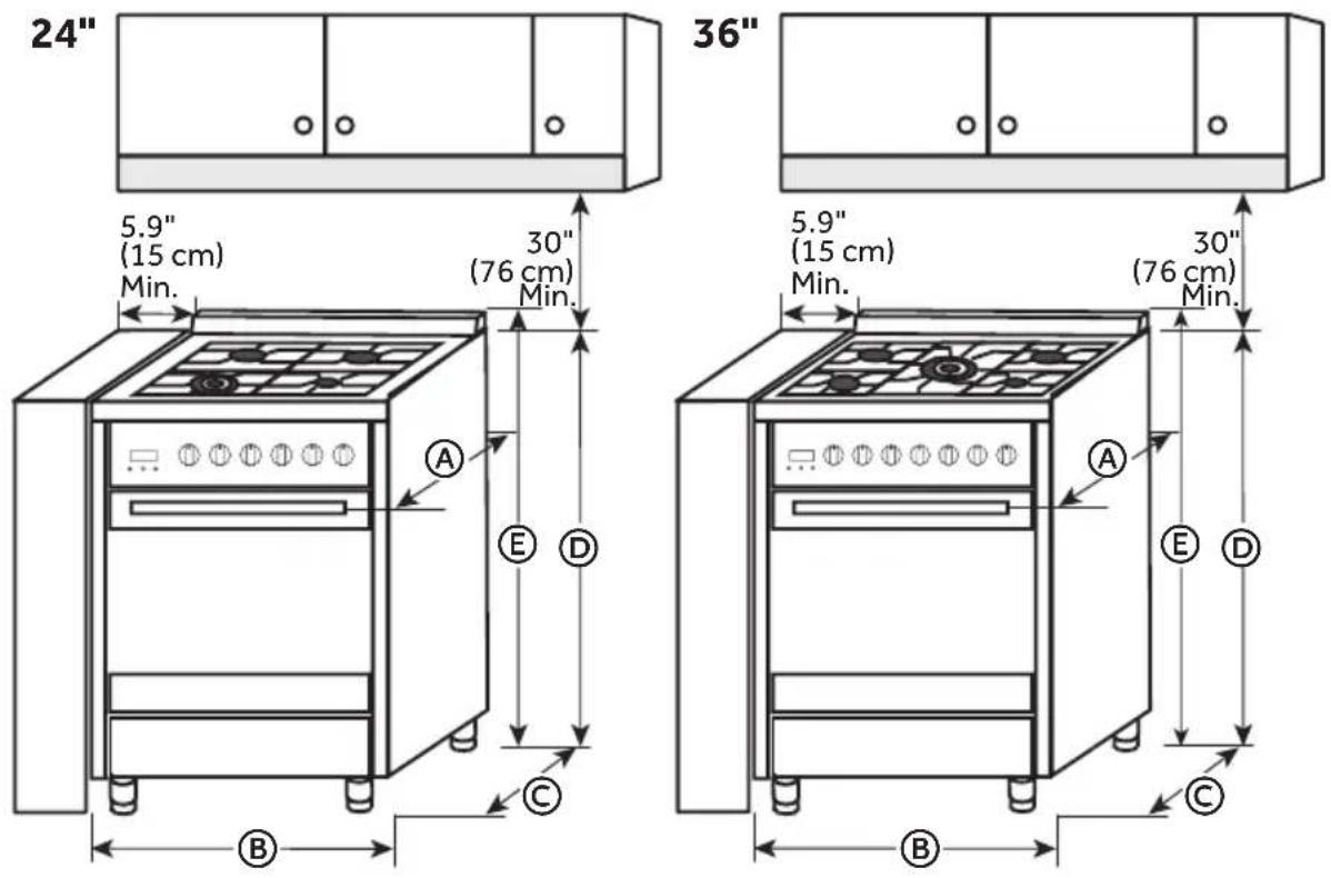
| Model Size | A. Depth w/ Handle | B. Width C. Depth | D. Height to top of Cooktop | E.Height Overall | |
| 24" | 25 15 " (64.28 cm) | 23 25 " (60 cm) | 23 35 " (60 cm) | 36" (91 cm) 37 35 " | (95.5 cm) |
| 36" | 25 15 " (64.28 cm) | 35 25 " (90 cm) | 23 35 " (60 cm) | 36" (91 cm) 37 35 " | (95.5 cm) |
NOTE: Range can be raised approximately 1" (2.5 cm) by adjusting the leveling legs. Front of door and drawer may extend farther forward depending on styling.
Back of Range
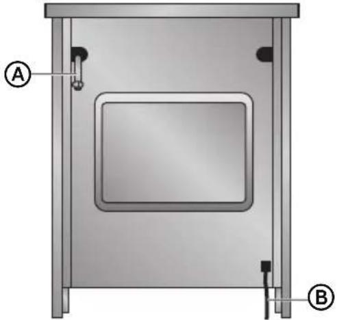
natural_image
Technical diagram of a rectangular enclosure or enclosure with labeled parts A and B, showing internal structure and mounting points (no text or symbols beyond labels)Ⓐ Gas Line from Range
B Power Cord
Power Supply
IMPORTANT: An electrical outlet in the floor, may be either recessed or surface mounted, but an electrical outlet in the wall must be recessed to make the connection.
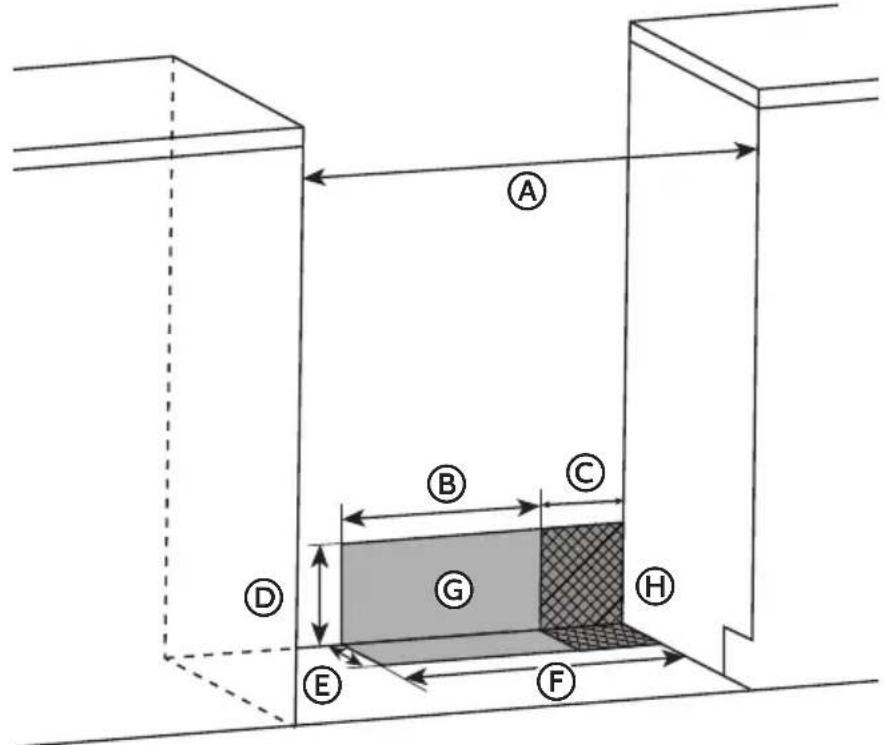
(A) 24" Model - 23 ^2/5 " (60 cm) 36" Model - 35 ^2/5 " (90 cm)
B 11½" (29.2 cm)
© 6" (15.2 cm)
(D) 7¼" (18.4 cm)
⑤ 3" (7.6 cm)
⑤ 17½" (44 cm)
G Recommended Location for Electrical Outlet
H Recommended Location for Gas Supply Connection
*NOTE: 24" (61.0 cm) minimum when bottom of wood or metal cabinet is covered by not less than 14 " (0.64 cm) flame retardant millboard covered with not less than No. 28 MSG sheet steel, 0.015" (0.4 mm) stainless steel, 0.024" (0.6 mm) aluminum or 0.020" (0.5 mm) copper.
30" (76.2 cm) minimum clearance between the cooking and the bottom of an uncovered wood or metal cabinet.
WARNING
Electrical Shock Hazard
Plug into a grounded 3 prong outlet.
Do not remove the ground prong from the power cord plug.
Do not use an adapter.
Do not use an extension cord.
Failure to do so can result in death, fire or electrical shock.
IMPORTANT: The range must be electrically grounded in accordance with local codes and ordinances, or in the absence of local codes, with the National Electrical Code, ANSI/NFPA 70 or Canadian Electrical Code, CSA C22.1.
This range is equipped with an electronic ignition system that will not operate if plugged into an outlet that is not properly polarized.
If codes permit and a separate ground wire is used, it is recommended that a qualified electrical installer determine that the ground path is adequate.
A copy of the above code standards can be obtained from:
National Fire Protection Association
1 Batterymarch Park
Quincy, MA 02169-7471
CSA International
8501 East Pleasant Valley Road
Cleveland, OH 44131-5575
- A 120 volt, 60 Hz., AC only, 15-amp fused, electrical circuit is required. A time-delay fuse or circuit breaker is also recommended. It is recommended that a separate circuit serving only this range be provided.
- Electronic ignition systems operate within wide voltage limits, but proper grounding and polarity are necessary. Check that the outlet provides 120-volt power and is correctly grounded.
- This gas range is not required to be plugged into a GFCI (Ground-Fault Circuit Interrupter) outlet. It is recommended that you not plug an electric spark ignition gas range or any other major appliance into a GFCI wall outlet as it may cause the GFCI to trip during normal cycling.
- Performance of this range will not be affected if operated on a GFCI-protected circuit. However, occasional nuisance tripping of the GFCI breaker is possible due to the normal operating nature of electronic gas ranges.
- The wiring diagram is located on the back of the range in a clear plastic bag.
NOTE: The metal chassis of the range must be grounded in order for the control panel to work. If the metal chassis of the range is not grounded, no keypads will operate. Check with a qualified electrician if you are in doubt as to whether the metal chassis of the range is grounded.
GAS SUPPLY REQUIREMENTS
WARNING
Explosion Hazard
Use a new CSA International approved gas supply line.
Install a shut-off valve.
Securely tighten all gas connections.
If connected to LP, have a qualified person make sure gas pressure does not exceed 14" (36 cm) water column.
Examples of a qualified person include:
licensed heating personnel, authorized gas company personnel, and authorized service personnel.
Failure to do so can result in death, explosion or fire.
Observe all governing codes and ordinances.
IMPORTANT: This installation must conform with all local codes and ordinances. In the absence of local codes, installation must conform with American National Standard, National Fuel Gas Code ANSI Z223.1 - latest edition or CAN/CGA B149 – latest edition.
IMPORTANT: Leak testing of the range must be conducted according to the manufacturers instructions.
TYPE OF GAS
Natural gas:
This range is design-certified by CSA International for use with Natural gas or, after proper conversion, for use with LP gas.
- This range is factory set for use with Natural gas. See “Gas Conversions” section. The model/serial rating plate located on the right side oven door trim has information on the types of gas that can be used. If the types of gas listed do not include the type of gas available, check with the local gas supplier.
LP gas conversion:
IMPORTANT: Conversion must be done by a qualified service technician.
No attempt shall be made to convert the appliance from the gas speci ed on the model/serial rating plate for use with a di erent gas without consulting the serving gas supplier. See "Gas Conversions" section.
GAS SUPPLY LINE
Provide a gas supply line of 34 " (1.9 cm) rigid pipe to the range location. A smaller size pipe on longer runs may result in insu cient gas supply. Pipe-joint compounds that resist the action of LP gas must be used. With LP gas, piping or tubing size can be 12 " (1.3 cm) minimum. Usually, LP gas suppliers determine the size and materials used in the system.
Gas Shut-off Valve:
- The gas supply line must be equipped with a manual shuto valve. This valve should be located in the same room but external to the range. It should be in a location that allows ease of opening and closing. Do not block access to shuto valve. The valve is for turning on or shutting o gas to the range.
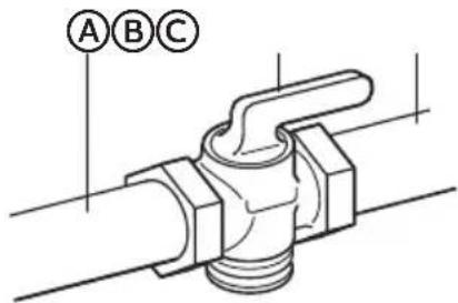
Ⓐ Gas Supply Line
⑧ Shuto Valve "Open" Position
© Flexible/Rigid Gas Line to Range
Flexible metal appliance connector:
- If local codes permit, a new CSA design-certi ed, 4 - 5 ft (122 - 152.4 cm) long, " (1.3 cm) or " (1.9 cm) I.D., exible metal appliance connector may be used for connecting range to the gas supply line.
natural_image
Line drawing of a flexible hose with connectors (no text or symbols)- A 12 " (1.3 cm) male pipe thread is needed for connection to the female pipe threads of the inlet to the appliance pressure regulator.
- Do not kink or damage the exible metal tubing when moving the range.
Rigid pipe connection:
The rigid pipe connection requires a combination of pipe fittings to obtain an in-line connection to the range. The rigid pipe must be level with the range connection. All strains must be removed from the supply and fuel lines so range will be level and in line.
natural_image
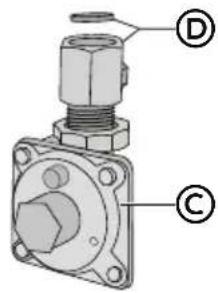
Technical line drawing of a pipe fitting with hexagonal connectors (no text or symbols)The gas pressure regulator supplied with this range must be used. The inlet pressure to the regulator should be as follows for proper operation:
Natural gas:
Minimum pressure: 5" Water Column Pressure (WCP)
Maximum pressure: 14" WCP
LP gas:
Minimum pressure: 11" WCP
Maximum pressure: 14" WCP
Contact local gas supplier if you are not sure about the inlet pressure.
Burner Input Requirements
Input ratings shown on the model/serial rating plate are for elevations up to 2,000 ft (609.6 m).
For elevations above 2,000 ft (609.6 m), ratings are reduced at a rate of 4% for each 1,000 ft (304.8 m) above sea level (not applicable for Canada).
GAS SUPPLY PRESSURE TESTING
Gas supply pressure for testing regulator must be at least 1" Water Column Pressure (WCP) above the manifold pressure shown on the model/serial rating plate.
Line pressure testing above 0.5 psi gauge (14" WCP)
The range and its individual shutoff valve must be disconnected from the gas supply piping system during any pressure testing of that system at test pressures in excess of 0.5 psi (3.5 kPa).
Line pressure testing at 0.5 psi gauge (14" WCP) or lower
The range must be isolated from the gas supply piping system by closing its individual manual shutoff valve during any pressure testing of the gas supply piping system at test pressures equal to or less than 0.5 psi (3.5 kPa).
INSTALLATION INSTRUCTIONS
IMPORTANT: This appliance shall be installed only by authorized persons and in accordance with the manufacturer's installation instructions, local gas fitting regulations, municipal building codes, electrical wiring regulations, local water supply regulations.
STEP 1 - UNPACK RANGE
WARNING
Excessive Weight Hazard
Use two or more people to move and install range.
Failure to do so can result in back or other injury.
- Remove shipping materials, tape and film from the range. Keep cardboard bottom under range. Do not dispose of anything until the installation is complete.
- Remove oven racks and parts package from oven and shipping materials.
- To remove cardboard bottom, first take 4 cardboard corners from the carton. Stack one cardboard corner on top of another. Repeat with the other 2 corners. Place them lengthwise on the floor behind the range to support the range when it is laid on its back.
- Using two or more people, firmly grasp the range and gently lay it on its back on the cardboard corners.
- Remove cardboard bottom.
NOTES:
- The leveling legs can be adjusted while the range is on its back.
- To place range back up into a standing position, put a sheet of cardboard or hardboard on the floor in front of range to protect the flooring. Using two or more people, stand range back up onto the cardboard or hardboard.
STEP 2 - INSTALL BACKSPLASH
For proper ventilation and to protect your wall from splatters, install the backsplash to the rear edge of the cooktop which extends past the back of the oven.
Parts Provided: Screws (6)
NOTE: 24" model uses (4) screws and the 36" model uses (6) screws
- Align the holes in the backsplash with the holes in the back edge of the cooktop.
- With one person holding the backsplash, and working from underneath the extended rear edge, insert screws through the bottom of the cooktop and into the bottom of the backsplash. Tighten completely.
NOTE: 24" model uses (2) screws and the 36" model uses (4) screws
24" Model
a Backsplash -Back Edge
b Backsplash - Bottom Edge
36" Model
a Backsplash -Back Edge
b Backsplash - Bottom Edge
- Insert the two screws (one on each side) through the back edge of the backsplash and into the cooktop. Tighten completely.
STEP 3 - INSTALL ANTI-TIP BRACKET
An Anti-Tip Bracket kit is provided with the range.
WARNING
natural_image
Silhouette of a small figure pushing a large block on a horizontal line (no text or symbols)Tip Over Hazard
A child or adult can tip the range and be killed.
Connect anti-tip bracket to rear range foot.
Reconnect the anti-tip bracket, if the range is moved.
Failure to follow these instructions can result in death or serious burns to children and adults.
IMPORTANT: Do not completely remove the rear leveling leg. The anti-tip bracket uses either the right-hand or left-hand, rear leveling leg to secure the range to the floor.
- Remove the anti-tip bracket from where it is taped inside the oven or storage drawer.
- Determine and mark centerline of the opening.
NOTE: The anti-tip bracket can be installed on either the left-hand side or right-hand side of the opening.
- Place the anti-tip bracket onto the floor so that the distances from the center of the bracket to the center line and to the wall is correct for your model. See the following chart for the required distances.
- Drill two 18 " (3 mm) holes through the mounting holes in the anti-tip bracket and into the floor.
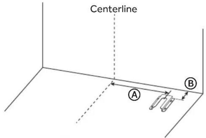
| Model Size Dimension A Dimension B | |
| 24" | 17 12 " (53.5 cm) 5" (12.7 cm) |
| 36" | 32 45 " (83.5 cm) 5" (12.7 cm) |
- Using the two screws provided, secure the anti-tip bracket to the floor.
NOTE: A rear leg of the range will be centered within the anti-tip bracket when it is moved into its final position.
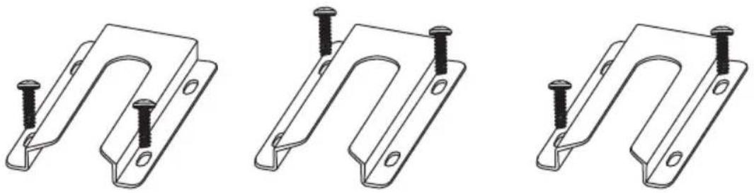
natural_image
Three technical line drawings of metal bracket components with mounting holes and bolts (no text or symbols)Front Position Rear Position Diagonal
STEP 4 - MAKE GAS CONNECTION
WARNING
Explosion Hazard
Use a new CSA International approved gas supply line.
Install a shut-off valve.
Securely tighten all gas connections.
If connected to LP, have a qualified person make sure gas pressure does not exceed 14" (36 cm) water column.
Examples of a qualified person include:
licensed heating personnel, authorized gas company personnel, and authorized service personnel.
Failure to do so can result in death, explosion or fire.
TYPICAL FLEXIBLE CONNECTION
CONNECT BSPP TO NPT ADAPTER TO GAS REGULATOR:
- Apply pipe-joint compound made for use with LP gas to the male threads of adapter ©.
- Insert adapter © into outlet of the gas pressure regulator, and then tighten using two 10" adjustable wrenches. Be sure flow arrow on regulator is pointing up toward the range gas inlet pipe.
- Install washer Ⓑ in female end of adapter Ⓒ, and then connect adapter Ⓒ to range gas inlet pipe Ⓔ via compression fitting and tighten.
NOTE: Washer Ⓑ must be used to create a leak proof seal.

Ⓐ Gas Line from Range
B Washer (provided)
© Adapter (provided)
(D) Gas Pressure Regulator (provided)
-
Apply pipe-joint compound made for use with LP gas to the tapered (NPT) threads of both adapters ^ID supplied with gas line kit.
-
Attach one adapter to the gas pressure regulator and the other to the gas shutoff valve and tighten both.
NOTE: Do Not rotate the gas pressure regulator.
- Attach the flexible gas line Ⓒ to adapters Ⓓ, one adapter at each end.
IMPORTANT: All connections must be wrench tightened (requires two 10" adjustable wrenches). Do not over-tighten the connections to the gas pressure regulator. Overtightening may crack the regulator creating a leak.
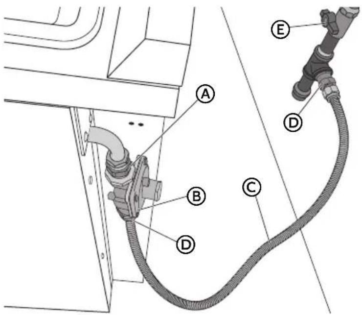
Ⓐ Adapter (provided)
B Gas Pressure Regulator
© Gas Supply Line
(D) Adapters (From Gas Supply Line Kit)
E Gas Shutoff Valve
COMPLETE CONNECTION
-
Open the manual shutoff valve in the gas supply line. The valve is open when the handle is parallel to the gas pipe.
-
Test all connections by brushing on an approved noncorrosive leak-detection solution. If bubbles appear, a leak is indicated. Correct any leak found.
STEP 5 - MAKE ELECTRICAL CONNECTION
WARNING

Electrical Shock Hazard
Plug into a grounded 3 prong outlet.
Do not remove the ground prong from the power cord plug.
Do not use an adapter.
Do not use an extension cord.
Failure to do so can result in death, fire or electrical shock.
- Slide range close to final location.
- Plug into a grounded 3 prong outlet.
STEP 6 - INSTALL RANGE
IMPORTANT: If the range is moved to adjust the leveling legs, make sure when you move the range back into its final location that the anti-tip bracket is engaged by repeating steps 1 through 8.
- Slide range into final location, making sure rear leveling leg slides into anti-tip bracket. Leave a 1" (2.5 cm) gap between the back of the range and the back wall.
- Place the outside of your foot against the bottom front to keep the range from moving, and then grasp the back of the range, as shown.
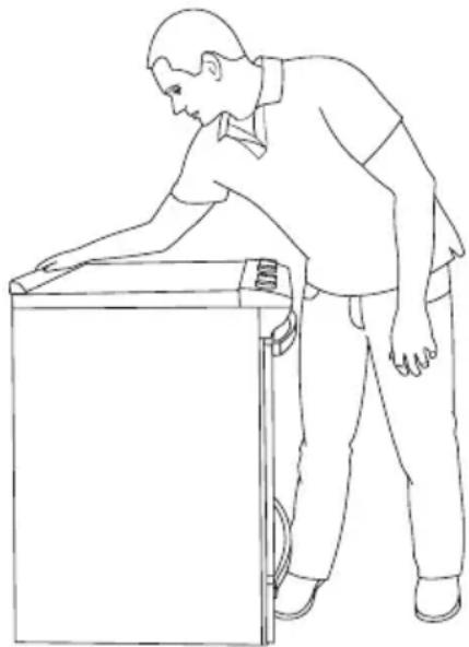
natural_image
Line drawing of a person leaning against the side of a refrigerator (no text or symbols)- Slowly attempt to tilt the range forward.
If you encounter immediate resistance, the range foot is engaged in the anti-tip bracket. Go to Step 8.
- If the rear of the range lifts more than 12 " (1.3 cm) off the floor without resistance, stop tilting the range and lower it gently back to the floor. The range foot is not engaged in the anti-tip bracket.
IMPORTANT: If there is a snapping or popping sound when lifting the range, the range may not be fully engaged in the bracket. Check to see if there are obstructions keeping the range from sliding to the wall or keeping the range foot from sliding into the bracket. Verify that the bracket is held securely in place by the mounting screws.
-
Slide the range forward, and verify that the anti-tip bracket is securely attached to the floor or wall.
-
Slide range back so the rear range foot is inserted into the slot of the anti-tip bracket.
-
Repeat steps 1 and 2 to ensure that the range foot is engaged in the anti-tip bracket.
If the rear of the range lifts more than 12 " (1.3 cm) off the floor without resistance, the anti-tip bracket may not be installed correctly. Do not operate the range without anti-tip bracket installed and engaged.
- Move the range into its final location. Place a carpenter's level on the oven floor to check that the range is level from side to side and front to back.
NOTE: The range must be level for optimum cooking and baking performance.
- If needed, use a wrench to adjust the height of the leveling legs until the range is level from side to side and front to back. See "Level the Range."
STEP 7 - LEVEL THE RANGE (IF NEEDED)
IMPORTANT: The range must be level.
The Range can be raised approximately 2" (5 cm) by adjusting the leveling legs.
- If the range is not level, pull the range forward until rear leveling leg is disengaged from the anti-tip bracket.
- Place a standard flat rack in oven.
- Place the level on the rack.
- Using a wrench or pliers, adjust the leveling legs up or down until the range is level.
- Push range back into position. Check that rear leveling leg is engaged in the anti-tip bracket.
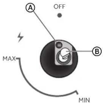
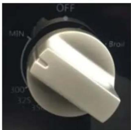
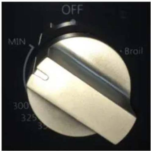
The cooktop and oven burners use electronic igniters in place of standing pilots. When the cooktop control knob is turned to the "ICON" position, the system creates a spark to light the burner.
This sparking continues, as long as the control knob is turned to "ICON."
When the oven control is turned to the desired setting, sparking occurs and ignites the gas.
Check Operation of Standard Surface Burners:
Push in and turn each control knob to the "ICON" position. The flame should light within 4 seconds. The first time a burner is lit, it may take longer than 4 seconds to light because of air in the gas line.
If burners do not light properly:
- Turn burner control knob to the "OFF" position.
- Check that the range is plugged in. Check that the circuit breaker has not tripped or the household fuse has not blown.
- Check that the gas shutoff valves are set to the "open" position.
- Check that burner caps are properly positioned on burner bases.
Repeat start-up. If a burner does not light at this point, turn the control knobs to the "OFF" position and contact your dealer or authorized service company for assistance.
To adjust flame height:
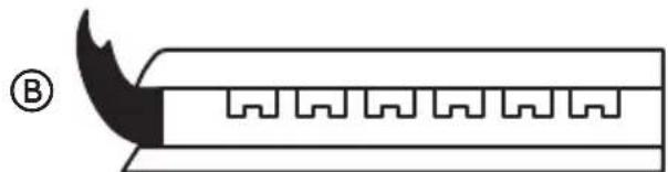
Adjust the height of burner flames. The cooktop "low" burner flame should be a steady blue flame approximately 14 " (6.4 mm) high.
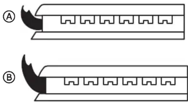
natural_image
Two identical diagrams of a mechanical component with serrated edges and triangular cutouts, labeled A and B (no text or symbols on the components themselves)A
Low Flame
B
High Flame
To adjust standard burner:
IMPORTANT: Adjustments must be made with two other burners in operation on a medium setting. This prevents the upper row of flames from being set too low, resulting in the flame being extinguished when other burners are turned on.
The flame can be adjusted using the adjustment screw in the center of the valve stem. The valve stem is located directly behind the control knob.
If the low flame needs to be adjusted:

Adjustment Screw

Control Knob Stem
- Light one burner and turn the control knob to the lowest setting.
- Remove the control knob.
-
Insert a small, flat-blade screwdriver into the adjustment screw, and slowly turn the screw until the flame appearance is correct.
-
Open the valve more if the flames are too small or fluttered.
-
Close the valve more if the flames are too large.
-
Replace the control knob.
-
Test the flame by turning the control from "LO" to "HI," checking the flame at each setting.
- Repeat above steps for each burner.
GAS CONVERSION
WARNING
Explosion Hazard
Use a new CSA International approved gas supply line.
Install a shut-off valve.
Securely tighten all gas connections.
If connected to LP, have a qualified person make sure gas pressure does not exceed 14" (36 cm) water column.
Examples of a qualified person include:
licensed heating personnel, authorized gas company personnel, and authorized service personnel.
Failure to do so can result in death, explosion or fire.
LP/PROPANE GAS CONVERSION
This appliance can be used with Natural Gas or LP/Propane gas. It is shipped from the factory for use with natural gas. A kit for converting to LP gas is supplied with your cooktop. The kit is marked "FOR LP/PROPANE GAS CONVERSION".
When the cooktop is converted for liquid petroleum (LP) gas, the LP gas supply is required to provide a minimum of 10" to a maximum of 14" water column to the cooktop regulator.
The conversion must be performed by a qualified service technician in accordance with the kit instructions and all local codes and requirements. Failure to follow instructions could result in serious injury or property damage. The qualified agency performing this work assumes responsibility for the conversion.
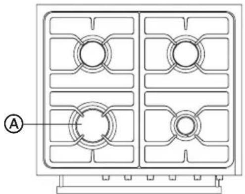
24" Burner and Orifice Characteristic Table
| Burner | Position | Orifice | Gas | Gas | Rate |
| Diam.(mm) | Type | [i.w.c.] | [BTU/h] | ||
| Auxiliary | Front R | 1.1 | NG | 4" | 5074 |
| 0.7 | LP (Propane) | 10" | 4922 | ||
| Semi-Rapid | Rear L | 1.29 | NG | 4" | 6859 |
| 0.8 | LP (Propane) | 10" | 6859 | ||
| Triple | Front L | 5 * 0.99 | NG | 4" | 17357 |
| 5 * 05.6 | LP (Propane) | 10" | 15048 | ||
| Rapid | Rear R | 1.29 | NG | 4" | 6859 |
| 0.8 | LP (Propane) | 10" | 6859 | ||
| Bake | Oven Lower | 1.7 | NG | 4" | 10710 |
| 1.0 | LP (Propane) | 10" | 10764 | ||
| Broil | Oven Upper | 1.4 | NG | 4" | 7915 |
| 0.85 | LP (Propane) | 10" | 7854 |
natural_image
Technical line drawing of a four-panel electrical panel with circular cutouts and mounting base (no text or symbols)Ⓐ Opening in grate for wok ring (provided) is located over left front burner.
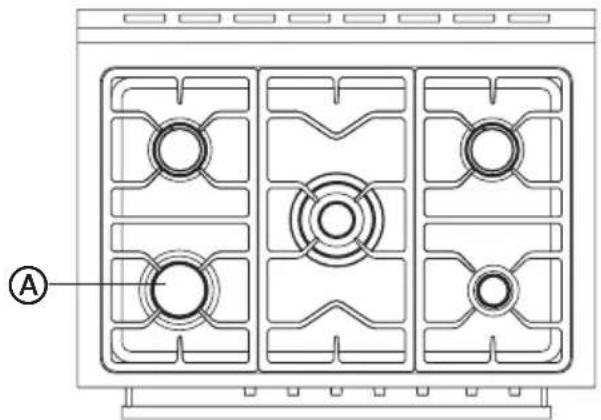
36" Burner and Orifice Characteristic Table
| Burner | Position | Orifice | Gas | Gas | Rate |
| Diam. (mm) | Type | [i.w.c.] | [BTU/h] | ||
| Auxiliary | Front R | 1.1 | NG | 4" | 5000 |
| 0.7 | LP (Propane) | 10" | 5000 | ||
| Semi-Rapid | Rear L and R | 1.29 | NG | 4" | 6859 |
| 0.8 | LP (Propane) | 10" | 6859 | ||
| Dual Burner | Middle | 0.99*5 | NG | 4" | 17357 |
| 0.56*5 | LP (Propane) | 10" | 15000 | ||
| Rapid Burner | Front L | 1.45 | NG | 4" | 8500 |
| 0.91 | LP (Propane) | 10" | 8500 | ||
| Bake | Oven Lower | 1.95 | NG | 4" | 14167 |
| 1.15 | LP (Propane) | 10" | 13868 | ||
| Broil | Oven Upper | 1.49 | NG | 4" | 9300 |
| 0.93 | LP (Propane) | 10" | 9237 |
natural_image
Technical line drawing of a four-panel electric stove fan with mounting holes and internal circuitry (no text or symbols)Ⓐ Opening in grate for wok ring (provided) is located over left front burner.
Tools Needed for Conversion:
- Wrench
• 7 mm Nut Driver - Safety Glasses
• Small Flat-head Screwdriver
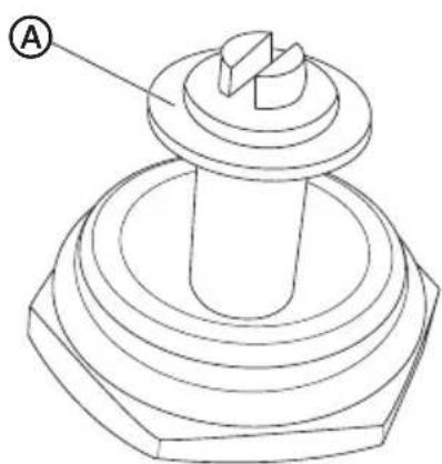
STEP 1 - ADJUST THE REGULATOR
IMPORTANT: Disconnect all electrical power, at the main circuit breaker or fuse box. Shut off the gas supply to the range by closing the manual shut-off valve.
- Unscrew the regulator cap with the wrench.
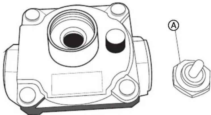
natural_image
Technical line drawing of a mechanical component with mounting holes and a labeled switch (no text or symbols present)A
Regulator Cap
- Remove the retainer pin that is currently positioned for use with Natural Gas.
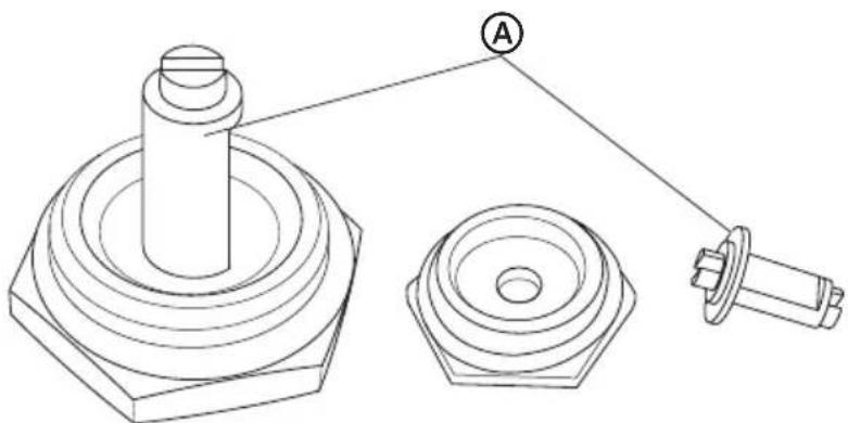
natural_image
Technical line drawing of mechanical components including a cylindrical shaft, flange, and bolt (no text or symbols)A
Retainer Pin
- Turn the retainer pin upside down and replace it into the regulator cap. It is now positioned for use with LP gas.
natural_image
Technical line drawing of a mechanical component with concentric rings and a central shaft (no text or symbols)A
Retainer Pin
- Remove the screw securing the front of the burner to the cavity. Lower burner and gently move aside to access broil orifice.
- Remove the natural gas broil orifice and replace with the 0.85 Diam. LP orifice. Reinstall burner.
- Remove the bake burner cover. It slides forward for removal.
- Remove the 2 screws securing the bake burner at the front and rear. Remove and set burner aside.
natural_image
Close-up of a metallic mechanical component with circular holes and a central shaft, showing no visible text or symbols.
natural_image
Close-up of a metallic mechanical component with evenly spaced teeth and central holes (no visible text or symbols)- Remove the natural gas bake orifice and replace with the 1.0 Diam. LP orifice. Reinstall burner.
- To adjust oven burner: The flame can be adjusted using the adjustment screw behind the oven control knob.
If the low flame needs to be adjusted: Light bake burner and turn the oven control knob to the lowest setting. Wait 5 minutes then remove knob. Insert a small, flat-blade screwdriver into the adjustment screw, and slowly turn the screw until the flame appearance is correct.
- Open the valve more if the flames are too small or fluttered.
- Close the valve more if the flames are too large.
Replace Knob.
natural_image
Close-up of a white industrial rotary knob with no visible text or symbols on the knob itself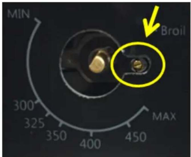
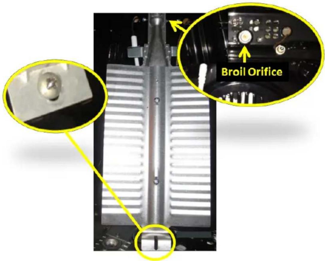
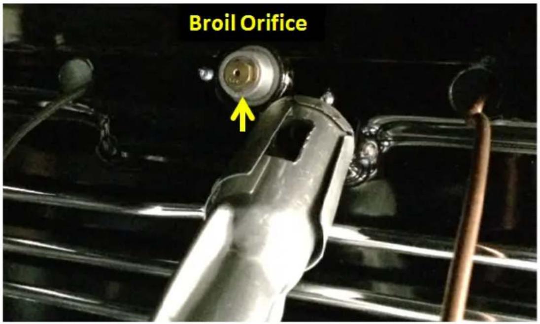
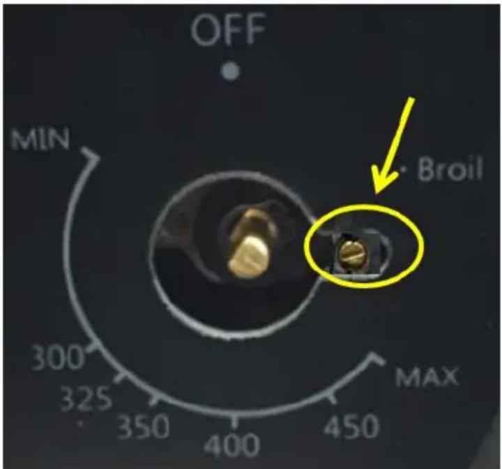
STEP 6 - CHANGE OVEN BURNER ORIFICES (HCR6250AGS)
- Disconnect power to the range.
- Locate broil burner. The broil orifice is located on the upper right of the oven cavity, behind the broil burner. The broil burner must be removed to gain access to the broil orifice.
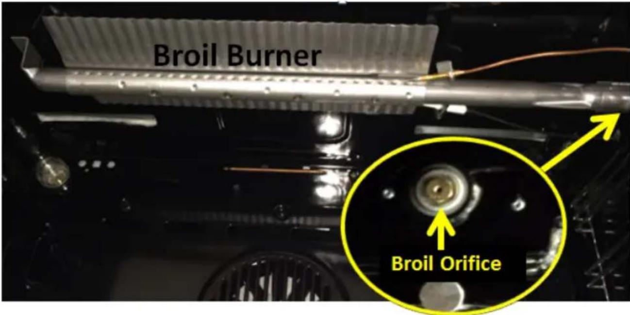
3- Remove the screw securing the front of the broil burner to the cavity. Lower burner and gently move aside to access broil orifice.
natural_image
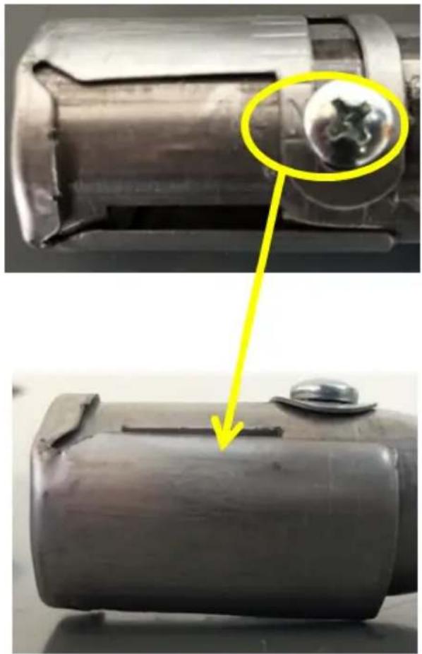
Close-up of a metallic mechanical device with a highlighted inset showing a close-up of a component (no visible text or symbols)- Remove the natural gas broil orifice and replace with the 0.85 Diam. LP orifice.
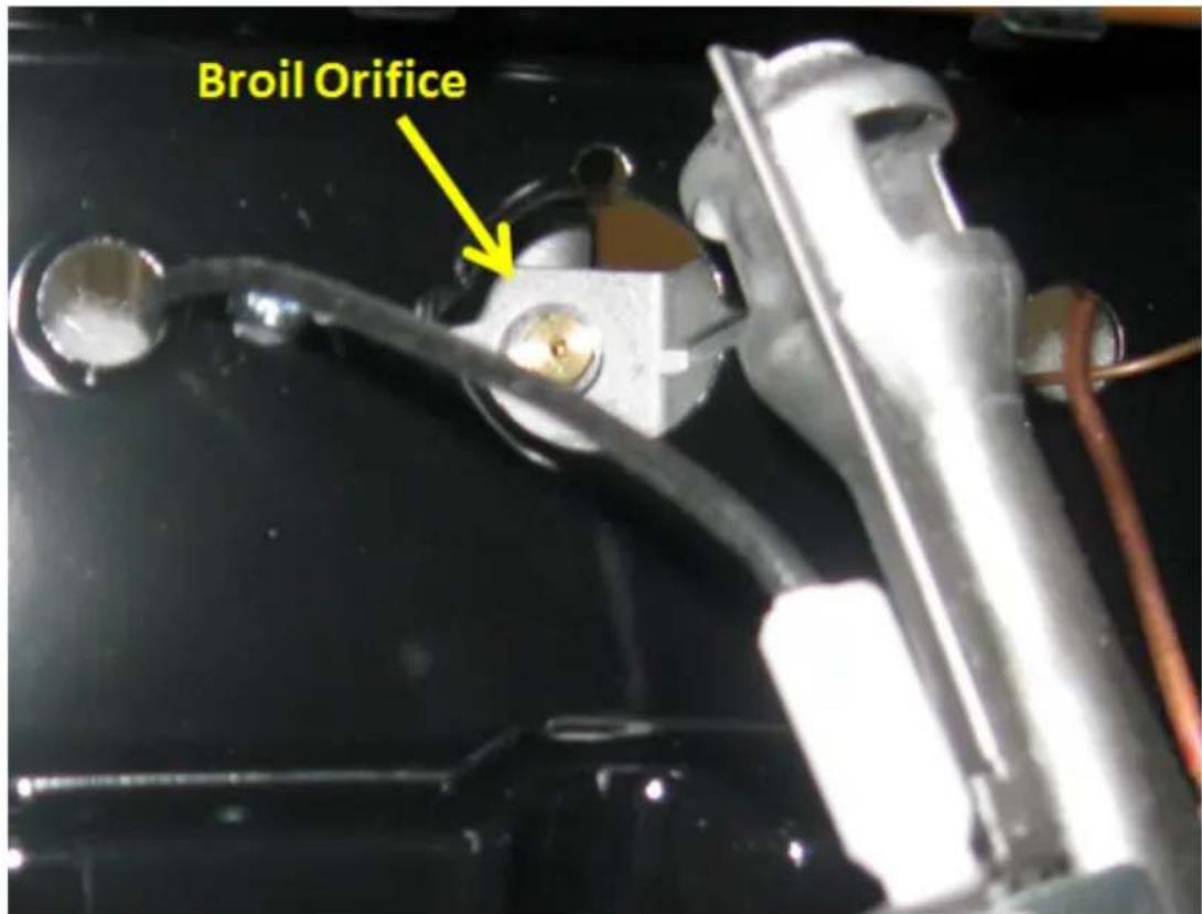
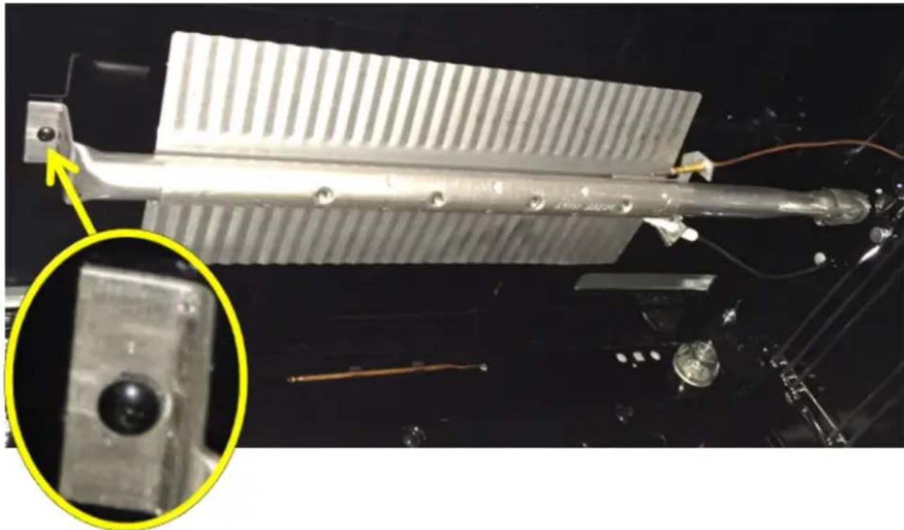
- (HCR6250AGS only) Set the burner air shutter for LP Gas. Loosen the shutter set screw and turn the shutter from the N (natural gas) position to the GPL (LP gas) position. Tighten shutter set screw and reinstall burner.
Natural Gas position
natural_image
Close-up of a damaged mechanical component with a highlighted circular feature and a yellow arrow pointing to a detail (no text or symbols visible)LP Gas position
natural_image
Close-up of a metallic mechanical component with a highlighted circular feature and a yellow arrow pointing to it (no text or symbols visible)- Remove the bake burner cover. Lift it up for removal.
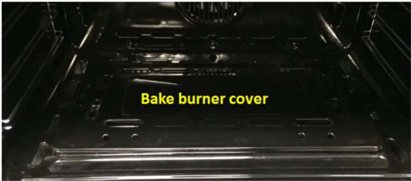
- Remove the screw securing the bake burner. Its located on the left at the end of the burner. Gently move burner aside to access the bake orifice.
natural_image
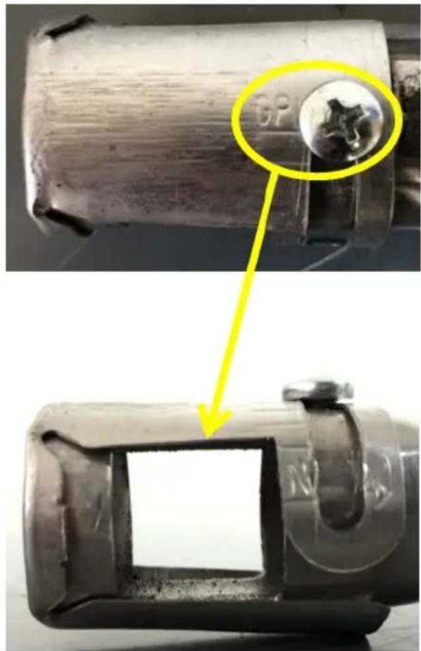
Close-up of a mechanical component with a highlighted inset showing a close-up view of a small object (no text or symbols visible)- Remove the natural gas bake orifice and replace with the 0.85 Diam. LP orifice.
- (HCR6250AGS only) Set the burner air shutter for LP Gas. Loosen the shutter set screw and turn the shutter from the N (natural gas) position to the GPL (LP gas) position. Tighten shutter set screw and reinstall burner.
Natural Gas position
natural_image
Close-up of a damaged mechanical component with a highlighted circular detail and a yellow arrow pointing to a defect (no text or symbols visible)LP Gas position
natural_image
Close-up of a metallic cylindrical component with a yellow arrow pointing to a circular feature, no visible text or symbols.- To adjust oven burner: The flame can be adjusted using the adjustment screw behind the oven control knob.
If the low flame needs to be adjusted: Light bake burner and turn the oven control knob to the lowest setting. Wait 5 minutes then remove knob. Insert a small, flat-blade screwdriver into the adjustment screw, and slowly turn the screw until the flame appearance is correct.
- Open the valve more if the flames are too small or fluttered.
- Close the valve more if the flames are too large.
Replace Knob.
IMPORTANT: Once the conversion has been completed and has passed testing, fill out the conversion sticker and include your name, organization and the date conversion is made. Apply the sticker near the cooktop gas inlet opening to alert others in the future that this appliance has been converted. If converting back to Natural Gas, please remove the sticker so others know that the appliance is set to use its original gas.
ABNORMAL OPERATION
ANY OF THE FOLLOWING ARE CONSIDERED TO BE ABNORMAL OPERATION AND MAY REQUIRE SERVICING:
• Yellow tipping of the hob burner flame.
- Sooting up of cooking utensils.
- Burners not igniting properly.
- Burners failing to remain lit.
- Burners extinguished by oven door.
• Gas valves, which are difficult to turn.
IN CASE THE APPLIANCE FAILS TO OPERATE CORRECTLY, CONTACT THE AUTHORIZED SERVICE PROVIDER IN YOUR AREA
TABLE DES MATIÈRES
SÉCURITÉ DE LA CUISINIÈRE ...... 29
EXIGENCES D'INSTALLATION....31
natural_image
Silhouette of a person pushing a large block on a horizontal line (no text or symbols)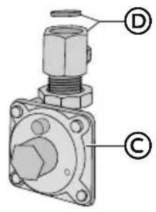
natural_image
Illustration of a bag with a pile of bolts and a labeled 'E' (no text or symbols on the objects themselves)Ⓐ Vis de 16 x 1 ^5/8 " (2)
© Détendeur
B La bride antibasculement
natural_image
Schematic illustration of a wavy, coiled cable or hose with connectors (no text or symbols)EXIGENCES D'EMPLACEMENT
VENTILATION
natural_image
Line drawing of a kitchen oven with a grater inside, showing structural layers and a labeled component (A), no text or symbols present.A
Plaque signalétique
TEMPÉRATURE
natural_image
Technical diagram of a rectangular enclosure or enclosure with labeled parts A and B, showing internal frame and side supports (no text or symbols beyond labels)National Fire Protection Association
1 Batterymarch Park
Quincy, MA 02169-7471
CSA International
8501 East Pleasant Valley Road
Cleveland, OH 44131-5575
natural_image
Schematic illustration of a flexible hose with connectors (no text or symbols)natural_image
Technical line drawing of a pipe fitting with hexagonal connectors (no text or symbols)DÉTENDEUR DE GAZ
natural_image
Silhouette of a person pushing a large block on a horizontal line (no text or symbols)natural_image
Three identical line drawings of metal bracket components with black bolts, shown from different angles (no text or symbols)natural_image
Line drawing of a person leaning against the side of a refrigerator (no text or symbols)natural_image
Pure diagram of a mechanical component with gear-like slots and a curved blade, no text or symbols presentnatural_image
Pure diagram of a mechanical component with a curved blade and zigzag grooves, no text or symbols present.natural_image
Technical line drawing of a four-panel electrical panel with mounting base (no text or symbols)natural_image
Technical line drawing of a three-panel electric stove with circular vented dividers (no text or symbols)natural_image
Technical line drawing of a mechanical component with a close-up view showing a dial and a labeled section (A), no text or symbols present.natural_image
Technical line drawing of mechanical components including a cylindrical shaft, hexagonal base, and flanged end (no text or symbols)natural_image
Technical line drawing of a mechanical component with concentric rings and a central shaft (no text or symbols)natural_image
Technical line drawing of a mechanical component with cross-sectional view (no text or symbols)ÉTAPE 2 - REMPLACEMENT DES ORIFICES DES BRÛLEURS
natural_image
Technical line drawing of a mechanical assembly with no visible text or symbols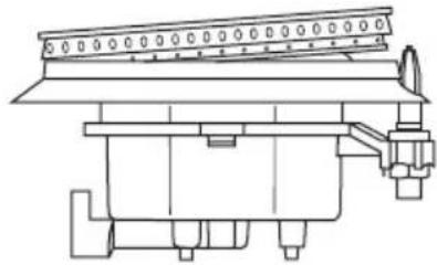
natural_image
Technical line drawing of a mechanical assembly with no visible text or symbolsInstallation correcte Installation incorrecte
ÉTAPE 3 - RÉGLAGE DES FLAMMES DES BRÛLEURS
REMARQUES :
natural_image
Pure diagram of a mechanical component with gear-like slots and a curved blade, no text or symbols presentnatural_image
Diagram of a mechanical component with a curved blade and zigzag grooves, labeled with circled B (no text or symbols on the diagram itself)natural_image
Silhouette of a person pushing a large block on a flat surface (no text or symbols)Peligro de Vuelco

natural_image
Simple line drawing of a bag with a pile of bolts and a label 'E' on the front face (no text or symbols on the bag itself)Ⓐ Tornillos #16 x 1 ^5/8 " (2)
B Soporte antivuelco
© Regulador
natural_image
Schematic illustration of a wavy cable or hose with connectors (no text or symbols)natural_image
Technical line drawing of an oven with a grating rack and labeled component (A), no text or symbols present.A
Placa indicadora
TEMPERATURA
natural_image
Technical diagram of a rectangular enclosure or chamber with labeled components A and B, showing internal structure and mounting points (no text or symbols beyond labels)A 24" Modelo - 23 ^2/5 " (60 cm) D 36" Modelo - 35 ^2/5 " (90 cm) E
⑧ 11½" (29,2 cm)
© 6" (15,2 cm)
7 ^1/4 " (18,4 cm)©
3" (7,6 cm)
17½" (44 cm)
National Fire Protection Association
1 Batterymarch Park
Quincy, MA 02169-7471
CSA International
8501 East Pleasant Valley Road
Cleveland, OH 44131-5575
natural_image
Line drawing of a wavy, coiled cable or pipe with connectors (no text or symbols)natural_image
Technical line drawing of a pipe fitting with hexagonal connectors (no text or symbols)A
A
natural_image
Silhouette of a person pushing a large block on a horizontal line (no text or symbols)Peligro de Vuelco
natural_image
Three technical line drawings of metal bracket components with mounting holes and bolts (no text or symbols)natural_image
Two identical diagrams of a mechanical component with serrated edges and triangular cutouts, labeled A and B (no text or symbols on the components themselves)natural_image
Technical line drawing of a four-panel grid structure with circular cutouts and mounting base (no text or symbols)natural_image
Technical line drawing of a four-panel electric stove with circular vented slots and a labeled component (A), no text or symbols present.natural_image
Technical line drawing of a mechanical component with concentric layers and a central shaft (no text or symbols)natural_image
Technical line drawing of a mechanical component with cross-sectional view and exploded view (no text or symbols)PASO 2 - CAMBIAR LAS BOQUILLAS DEL QUEMADOR
natural_image
Technical line drawing of a mechanical assembly with no visible text or symbols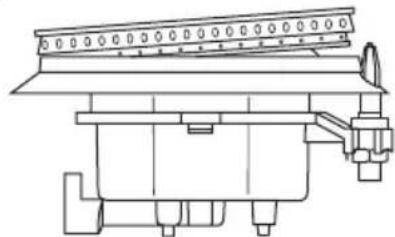
natural_image
Technical line drawing of a mechanical assembly with no visible text or symbolsnatural_image
Pure diagram of a mechanical component with no text or symbolsA
Llama baja
B
Llama alta
natural_image
Pure diagram of a mechanical component with a curved arrow and zigzag pattern, no text or symbols present.If you have a problem with this product, please contact the
"Haier Customer Satisfaction Center" at
1-877-337-3639.
DATED PROOF OF PURCHASE, MODEL #, AND SERIAL #
REQUIRED FOR WARRANTY SERVICE
IMPORTANT
Issued: April 2016 Printed in China Part # 0570000701 REV A


