
PV 16DR - Receiver PEAVEY - Free user manual and instructions
Find the device manual for free PV 16DR PEAVEY in PDF.

| Product Type | Dual Wireless Receiver |
| Brand | Peavey |
| Model | PV 16DR |
| Number of Channels | 16 UHF Channels |
| Tuning Type | Microprocessor-controlled PLL |
| Reception Method | Diversity (two antennas) |
| Audio Frequency Response | 50 Hz - 18 kHz (±3 dB) |
| Total Harmonic Distortion | 0.8% typical |
| Dynamic Range | > 100 dB (A-weighted) |
| Operating Range | 100 m (300 ft) |
| Sensitivity | -105 dBm (S/N ratio > 12 dB) |
| Image Rejection | > 60 dB |
| Audio Outputs | 1 balanced XLR output, 1 unbalanced output (jack) |
| Receiver Power Supply | 12-15 V DC (AC adapter included) |
| Transmitter Power Supply | 2 AA batteries (alkaline recommended) |
| Transmitter Battery Life | Approximately 8 hours (alkaline batteries) |
| Compatible Transmitter Types | Handheld (hand mic), bodypack (LT, GT), Lavalier, headset |
| Main Features | IR sync, AF level indicator, mute, control lock |
| Care and Cleaning | Wipe with a dry soft cloth. Avoid solvents. |
| Safety | Complies with Industry Canada RSS. Use only the provided adapter. |
Frequently Asked Questions - PV 16DR PEAVEY
User questions about PV 16DR PEAVEY
0 question about this device. Answer the ones you know or ask your own.
Ask a new question about this device
Download the instructions for your Receiver in PDF format for free! Find your manual PV 16DR - PEAVEY and take your electronic device back in hand. On this page are published all the documents necessary for the use of your device. PV 16DR by PEAVEY.
USER MANUAL PV 16DR PEAVEY
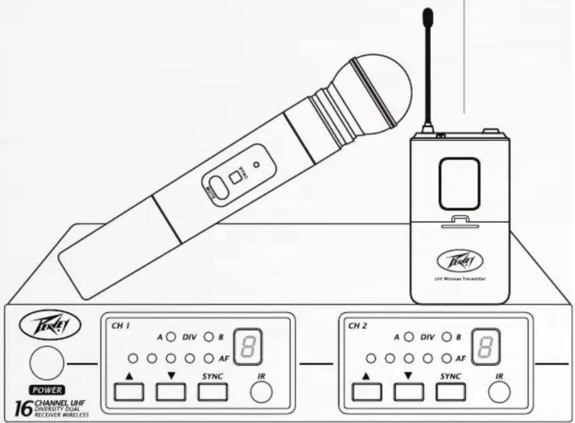
PV ^® 16-Channel Dual Receiver UHF
PLL Wireless Microphone System
This device complies with Part 15 of the FCC rules and Industry Canada license-exempt RSS Standard(s). Operation is subject to the following two conditions: (1) this device may not cause harmful interference, and (2) this device must accept any interference received, that may cause undesired operation.
Warning: Changes or modifications to the equipment not approved by Peavey Electronics Corp. can void the user's authority to use the equipment.
Note – This equipment has been tested and found to comply with the limits for a Class B digital device, pursuant to Part 15 of the FCC Rules. These limits are designed to provide reasonable protection against harmful interference in a residential installation. This equipment generates, uses, and can radiate radio frequency energy and, if not installed and used in accordance with the instructions, may cause harmful interference to radio communications. However, there is no guarantee that interference will not occur in a particular installation. If this equipment does cause harmful interference to radio or television reception, which can be determined by turning the equipment off and on, the user is encouraged to try and correct the interference by one or more of the following measures.
• Reorient or relocate the receiving antenna.
- Increase the separation between the equipment and receiver.
- Connect the equipment into an outlet on a circuit different from that to which the receiver is connected.
- Consult the dealer or an experienced radio/TV technician for help.
(IC: 3642A-UH6)
(IC: 3642A-UB7)
Caution
The equipment complies with FCC radiation exposure limits set forth for an uncontrolled environment.

INTRODUCTION
ENGLISH
Please read this manual thoroughly for correct operation and optimal performance.
PV® 16 Channel Dual Receiver PLL Wireless Receiver Features
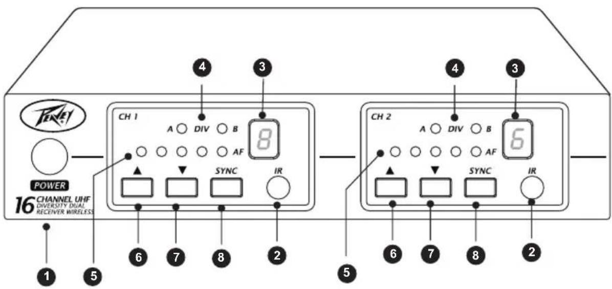
FRONT PANEL
(1) Power switch
(2) Infrared(IR) port: Broadcasts IR signal to transmitter.
(3) Channel indicator: To display system's receiving channel.
(4) DIV indicator: Antenna receiver status indicator LED.
(5) AF1 - AF5 indicator: Indicate the audio signal level.
(6) ▲P select button.
(7) DOWN select button.
(8) SYNC button: Press to synchronize transmitter and receiver frequencies.
NOTE: WHEN ch1 AND Ch2 ARE IN USE TOGETHER, PLEASE DON'T SET THEM ON THE SAME CHANNEL.
PV® 16 Channel Dual Receiver PLL Wireless Receiver Features
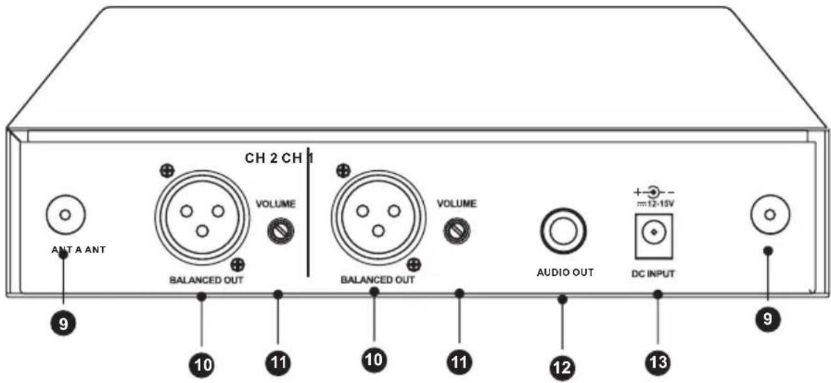
BACK PANEL
(9) Antenna connectors
(10) Balanced out Jack: XLR connector provides balanced audio output signal from this jack to the amplifier.
(11) Volume adjustment knob: Adjusts the volume level of the AUDIO OUT.
(12) Unbalanced out Jack: MIX OUTPUT, with Phone Jack provides audio output signal from this jack to the amplifier.
(13) DC input socket: Input socket for 12-15V Volt DC power. Please note that the polarity of the central pin in the socket is positive(+).
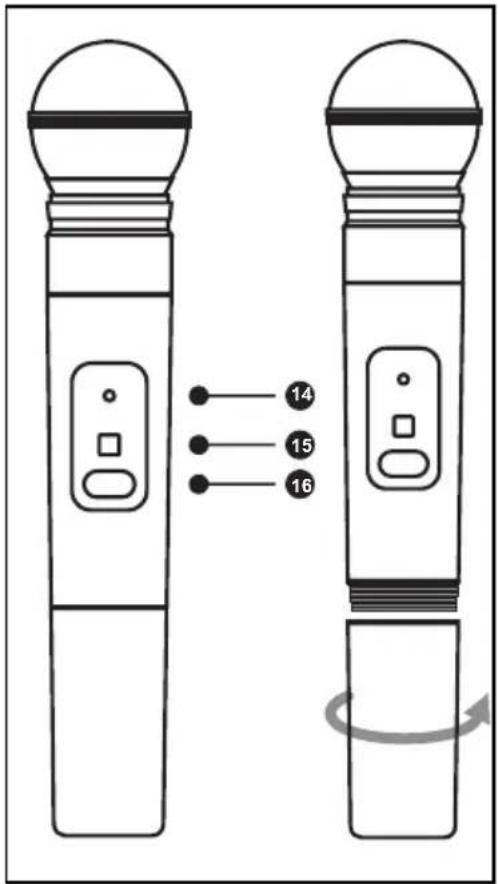
PV ^® 16 Channel Dual Receiver PLL Handheld Transmitter
(14) Power / IR mute indicator
(15) SYNC port: Receives infrared beam to synchronize frequencies
(16) On-off / mute switch: Press and hold to turn on or off. Press and release to mute or disengage mute function.
| Green | Ready |
| Flashing green | Controls locked |
| Amber | Mute on |
| Flashing red | IR transmitter in process |
| Glowing red | Battery power low |
| Pulsing red on startup | Batteries dead (transmitter cannot be turned on until batteries are changed) |
| Pulsing red after synchronization | Transmitter and receiver are incompatible |
CHANGING BATTERIES
- Expected life for alkaline batteries is approximately 8 hours.
- When the transmitter light glows red, the batteries should be replaced, as shown.
When the Transmitter is not in use:
Make sure the microphone is turned off. If the microphone will not be used for an extended period of time, please remove the batteries to avoid battery leakage that can result in damage to the battery springs and circuit.
PV ^® 16 Channel Dual Receiver Body Pack Transmitter
Green
Flashing green
Amber
Flashing red
Glowing red
Pulsing red on startup
Pulsing red after synchronization
Ready
Controls locked
Mute on
IR transmitter in process
Battery power low
Batteries dead (transmitter cannot be turned on until batteries are changed)
Transmitter and receiver incompatible
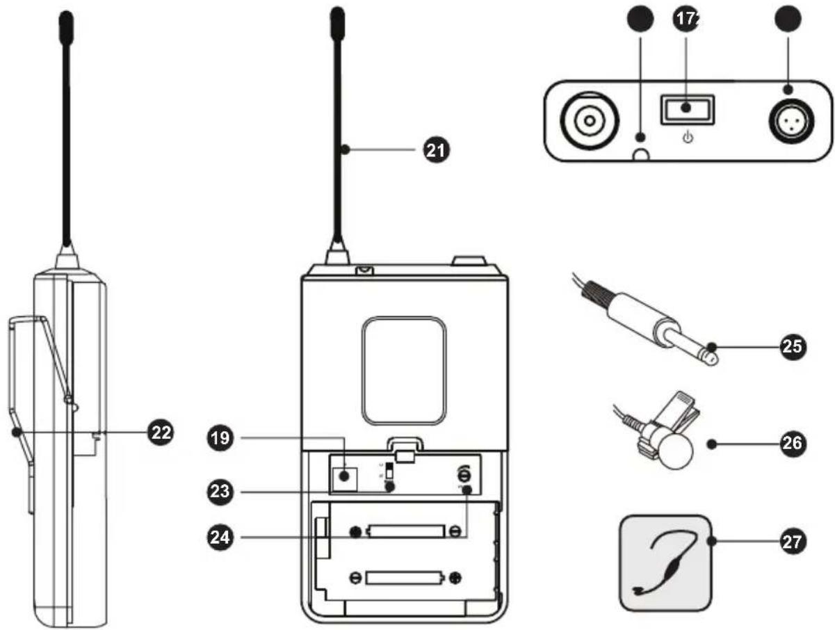
BODYPACK TRANSMITTER
(17) Power / Mute Button
(18) Mic Jack
(19) IR Port
(20) Power / IR / Mute indicator
(21) Transmitter Antenna
(22) Detachable Belt Clip
(23) Mode with LT & GT
(24) Volume Adjustment
(25) Guitar Cable for guitar wireless system
(26) Lavalier Mic for lavalier wireless system
(27) Headphone Microphone for headset wireless system
natural_image
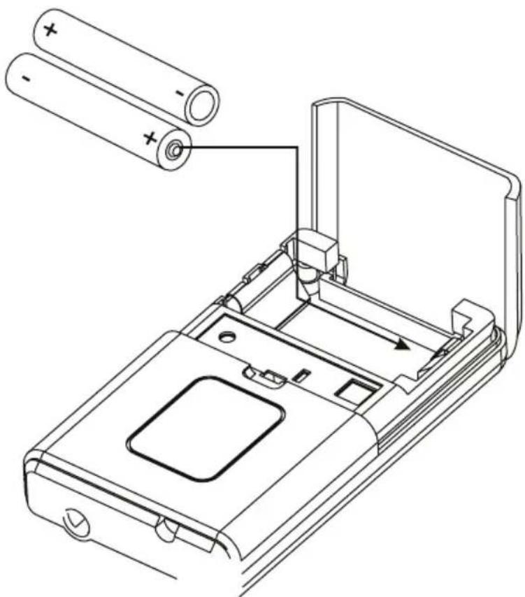
Technical line drawing of a device casing with two batteries inserted, showing internal components and a handle (no text or symbols)BODYPACK TRANSMITTER
CHANGING BATTERIES
- Expected life for alkaline batteries is approximately 8 hours.
- When the transmitter light glows red, the batteries should be replaced immediately, as shown.
When the Transmitter is not in use:
Make sure the microphone is turned off. If the microphone will not be used for an extended period of time, please remove the batteries to avoid battery leakage that can result in damage to the battery springs and circuit.
PV ^® 16 Channel Dual Receiver Body Pack Sync Function

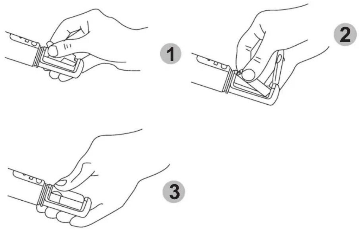
AUTOMATIC TRANSMITTER SETUP
Open the body pack transmitter battery compartment to display the infrared(SYNC) port.
With the transmitter SYNC port exposed to the receiver, press SYNC
When the receiver ready light glows, the system is ready for use.
Close the body pack transmitter battery compartment.
SPECIFICATIONS
SYSTEM FREQUENCY UHF
Audio Frequency Response Minimum: 50 Hz Maximum: 18 KHz
+/-3 dB (Overall system frequency depends on microphone element)
Total Harmonic Distortion 0.8%, typical
Ref.+/-30 KHz deviation,1 KHz tone
Dynamic Range >100 dB A-weighted
Working Range 100 m (300 ft.)
RX Oscillation Type Microprocessor controlled PLL Synthesized
Receiving Method Diversity
Frequency Stability +/- 0.005%
No. of Channels Max 16 (16 Channels)
Max Deviation >+/- 45 KHz
Sensitivity -105 dBm at S/N ratio >12 dB
Pilotone Frequency 32.768 KHz
Image Rejection >60 dB
Audio Outputs Unbalanced: 360 mV / 5 K
Balanced: 25 mV / 600
TX RF Power Output >30 mV
Spurious Emission >60 dB below Carrier
No. of Channels Max 16 (16 Channels)
Pilotone Frequency 32.768 KHz
Battery AA type*2
Battery Life (Alkaline) Estimated 8 hours
FRANÇAIS
INTRODUCTION
PANNEAU ARRIÈRE
natural_image
Technical line drawing of a device's internal components with two batteries and a handle (no text or symbols)BOÎTIER D'ÉMETTEUR
CHANGER LES PILES
Transmisor BodyPack y receptor de dos canales PV® 16

Verde
Verde destellante
Ámbar
Rojo destellante
natural_image
Technical line drawing of a device casing with two batteries inserted, showing internal components and a handle (no text or symbols)TRANSMISOR BODYPACK
natural_image
Abstract black-and-white graphic design resembling stylized figures or a bird, with no readable text or symbols.www.peavey.com
Warranty registration and information for U.S. customers available online at
www.peavey.com/warranty
or use the QR tag below

Features and specifications subject to change without notice.
Peavey Electronics Corporation
5022 Hartley Peavey Drive
Meridian, MS 39305
(601) 483-5365
FAX (601) 486-1278

Logo referenced in Directive 2002/96/EC Annex IV
(OJ(L)37/38,13.02.03 and defined In EN 50419: 2005
The bar is the symbol for marking of new waste and
is applied only to equipment manufactured after 12 August 2005
13 August 2005