
Airstage ASYE14GACH - Air Conditioning FUJITSU - Free user manual and instructions
Find the device manual for free Airstage ASYE14GACH FUJITSU in PDF.

| Product type | Indoor air conditioning, wall-mounted type, VRF system |
| Brand | Fujitsu |
| Model | Airstage ASYE14GACH |
| Power supply | 230 V ~ 50 Hz |
| Available voltage range | 198 to 264 V |
| Cooling capacity | 4.5 kW |
| Heating capacity | 5.0 kW |
| Dimensions (H x W x D) | 275 x 790 x 215 mm |
| Weight | 9 kg |
| Sound pressure level (Cooling) - High | 43 dB(A) |
| Sound pressure level (Cooling) - Med | 35 dB(A) |
| Sound pressure level (Cooling) - Low | 30 dB(A) |
| Operating modes | Cooling, Heating, Dehumidification, Automatic |
| Automatic defrost function | Yes, microcomputer-controlled |
| Automatic oil recovery | Yes, approximately 10 minutes |
| Airflow direction | Vertical (remote control) and horizontal (manual) |
| Air filters | Washable air filter, optional purification and deodorizing filter |
| Filter maintenance | Clean every 2 weeks during normal use period |
| Indoor temperature (Cooling) | 18 to 32 °C DB |
| Indoor temperature (Heating) | 10 to 30 °C DB |
| Maximum indoor humidity | Approximately 80% or less |
| Safety | Mandatory shutdown before cleaning, do not pour water, call an authorized technician for repairs |
| Repairability | Spare parts available from authorized after-sales service |
Frequently Asked Questions - Airstage ASYE14GACH FUJITSU
User questions about Airstage ASYE14GACH FUJITSU
0 question about this device. Answer the ones you know or ask your own.
Ask a new question about this device
Download the instructions for your Air Conditioning in PDF format for free! Find your manual Airstage ASYE14GACH - FUJITSU and take your electronic device back in hand. On this page are published all the documents necessary for the use of your device. Airstage ASYE14GACH by FUJITSU.
USER MANUAL Airstage ASYE14GACH FUJITSU
natural_image
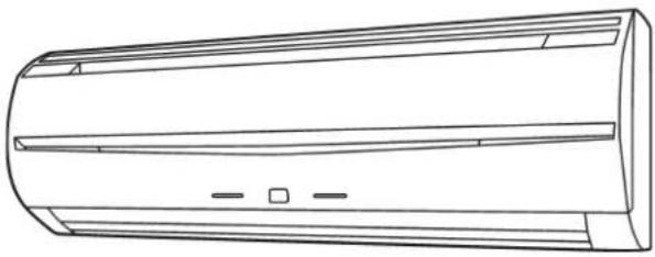
Line drawing of a cylindrical air conditioner unit with horizontal insulation bands and mounting holes (no text or symbols)ASYE07GACH / ASHE07GACH ASYE09GACH / ASHE09GACH ASYE12GACH / ASHE12GACH ASYE14GACH / ASHE14GACH ASYA07GACH / ASHA07GACH ASYA09GACH / ASHA09GACH ASYA12GACH / ASHA12GACH ASYA14GACH / ASHA14GACH
OPERATING MANUAL
INDOOR UNIT (Wall mounted type)
Keep this manual for future reference.
BEDIENUNGSANLEITUNG
VRF system indoor unit (Wall mounted type)
CONTENTS
SAFETY PRECAUTIONS 1
NAME OF PARTS 1
CLEANING AND CARE....3
TROUBLESHOOTING 4
SPECIFICATIONS....5
SAFETY PRECAUTIONS
Before using the appliance, read these "PRECAUTIONS" thoroughly and operate in the correct way.
- The instructions in this section all relate to safety; be sure to maintain save operating conditions.
"WARNING" and "CAUTION" have the following meanings in these instructions:
| This mark indicates procedures which, if improperly performed, might lead to the death or serious injury of the user. | |
| This mark indicates procedures which, if improperly performed, might possibly result in personal harm to the user, or damage to property. |
PRECAUTIONS ON USE
WARNING
- Do not keep exposing oneself to the direct wind of air conditioner for a long time.
- Do not insert fingers or objects into the outlet port or intake grilles.
Except for EMERGENCY, never turn off main as well as sub breaker of the indoor units during operation. It will cause compressor failure as well as water leakage.
First, stop the indoor unit by operating the control unit, converter or external input device and then cut the breaker.
Make sure to operate through the control unit, converter or external input device.
- If the power supply cord of this appliance is damaged, it should only be replaced by the authorized service personal, since special purpose tools and specified cord are required.
- If any refrigerant happens to leak, extinguish any flames, ventilate the room and get in touch with authorized service personnel.
CAUTION
Provide occasional ventilation during use.
- Do not use in applications involving the storage of foods, precision equipment, or art works.
- Do not place animals or plants in the direct path of the airflow.
- Do not direct airflow at fireplaces or heating apparatus.
Do not block or cover the inlet port and outlet port.
Do not climb on, or place objects on, the air conditioner.
- Do not set flower vases or water containers on top of air conditioners.
Do not hang objects from the indoor unit.
- Do not place anything below the indoor unit that should not get wet.
- Always turn off the electrical breaker whenever cleaning the air conditioner or the air filter.
- Do not pour water or cleaning solvent on the unit directly, or wash the unit with them.
Do not expose the air conditioner directly to water.
Do not operate the air conditioner with wet hands.
Check the condition of the installation stand for damage.
- Operate only with air filters installed.
Do not drink the water drained from the air conditioner. ● - Do not apply any heavy pressure to radiator fins.
- Do not use inflammable gases near the air conditioner.
Do not touch the piping during operation.
Ensure that any electronic equipment is at least 1 m away from either the indoor or outdoor units.
This appliance is not intended for use by persons (including children) with reduced physical, sensory or mental capabilities, or lack of experience and knowledge, unless they have been given supervision or instruction concerning use of the appliance by a person responsible for their safety. Children should be supervised to ensure that they do not play with the appliance.
Note: Switching the operating mode in the heat recovery system may require some time to prepare for operation. Please note that this is not a fault.
PRECAUTIONS ON INSTALLATION
CAUTION
Do not attempt to install this air conditioner by yourself.
This unit contains no user-serviceable parts.
Always consult authorized service personnel for repairs.
When moving, consult authorized service personnel for disconnection and installation of the unit.
The unit must be grounded.
Make sure drain work is implemented properly for drainage.
- Avoid installing the air conditioner near a fireplace or other heating apparatus.
When installing the indoor and outdoor unit, take precautions to prevent access to infants.
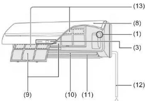
NAME OF PARTS
(1)
(3)
(8)
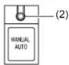
Operating Control Panel(1)
(2) MANUAL AUTO button: This is used to operate it while remote controller is not available.
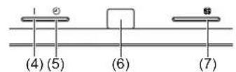
(3) Indicator Lamps
(4) OPERATION Indicator Lamp (green): It lights on while operating.
(5) TIMER Indicator Lamp (orange): It lights on while timer is working.
(6) Remote Control Signal Receiver: This is the place to receive the signals from the remote controller.
(7) FILTER Indicator Lamp (red): It lights on if the filter became dirty. Clean the filter referring to "CLEANING AND CARE". It lights off when RESET button is pressed after cleaning.
Intake Grille(8)
Air Filter(9)
Airflow Direction Louver(10)
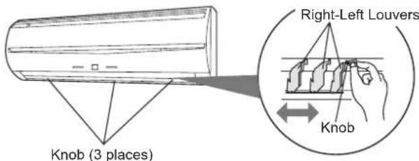
(11) Right-Left Louver (behind Airflow Direction Louver)
Drain Hose(12)
Air cleaning & deodorizing filter(13)
Control unit (optional)
| Wireless Remote Controller[3Y2T] | Wired Remote Controller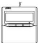 | Simple Remote Controller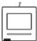 | 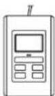 |
For operation method, please refer to the Operating Manual of each device.
Use the MANUAL AUTO operation in the event the remote control unit is lost or otherwise unavailable.

CAUTION
Do not press the MANUAL AUTO button with wet hands or pointed objects, otherwise an electric shock or malfunction may occur.
Starting Operation
Press the MANUAL AUTO button on the operating control panel.
The operation can be set in the following setting.
| Operating mode AUTO: | |
| Fan speed AUTO | |
| Setting temperature 23 °C | |
Stopping Operation
Press the MANUAL AUTO button on the operating control panel.
ADJUSTING THE DIRECTION OF AIR CIRCULATION
The vertical wind direction can be controlled with the control unit. The horizontal wind direction can be manually set by adjusting Right-Left Louvers.
Vertical direction

Cooling & Dry : (1), (2), (3), (4)
Heating : (1), (2), (3), (4)
Horizontal direction
OPERATING TIPS
Operation and Performance
About priority state and standby state
Multiple indoor units can be connected within the same system. Depending on the system, choice of operating mode are limited.
| Cooling priority state | When the other indoor units within the same system operate in cooling or dry mode, heating can not be selected at the same time. |
| Heating priority state | When the other indoor units within the same system operate in heating mode, cooling and dry mode can not be selected at the same time. |
| Standby state The | standby state activates when 2 or more indoor units start up at the same time in different mode.Any indoor unit other than priority mode will wait in standby state until priority mode changes (operation starts as soon as priority is switched).At this time, the operation indicator lamp (green) lights up and the timer indicator lamp (red) fl ashes. |
Low ambient cooling
When the outdoor temperature drops, the outdoor unit's fans may switch to Low Speed, or one of the fans may stop intermittently.
Heating performance
Heating mode operates on the heat-pump principle, absorbing heat from outdoor air and transferring that heat indoors. As a result, the operating performance is reduced as outdoor air temperature drops. If you feel that insufficient heating performance is being produced, we recommend you use this air conditioner in conjunction with another type of heating appliance.
- Heating mode heat your entire room by recirculating air throughout the room, with the result that some time may be required after first starting the air conditioner until the room is heated.
Microcomputer-controlled automatic defrosting
When using the Heating mode under conditions of low outdoor air temperature high humidity, frost may form on the outdoor unit, resulting in reduced operating performance. In order to prevent this kind of reduced performance, this unit is equipped with a Microcomputer-controlled automatic defrosting function. If frost forms, the air conditioner will temporarily stop, and the defrosting circuit will operate briefly (for about 4 to 15 minutes).
During Automatic Defrosting operation, the OPERATION indicator lamp (green) will flash.
Oil recovery operation
- Periodically, the oil recovery operation is performed in order to return compressor oil to the outdoor unit. During oil recovery operation, the OPERATION indicator lamp (green) will flash (for about 10 minutes).
Temperature and humidity range
The temperature and humidity required for operating this product is as shown in the following table.
| Cooling/Dry Mode Heating Mode | ||
| Outdoor temperature | Please refer to the specification of outdoor units. | |
| Indoor temperature | 18 to 32 °C DB 10 to | 30 °C DB |
| Indoor humidity | About 80% or less | |
If the air conditioner is operated under higher temperature conditions than those listed, the built-in protection circuit may operate to prevent internal circuit damage. Also, during Cooling and Dry modes, if the unit is used under conditions of lower temperature than those listed above, the heat-exchanger may freeze, leading to water leakage and other damage.
If the unit is used for long periods under high-humidity conditions, ● condensation may form on the surface of the indoor unit, and drip onto the floor or other objects underneath.
Do not use this unit for any purposes other than the Cooling, Heating, ● Dehumidifying, and air-circulation of rooms in ordinary dwellings.
CLEANING AND CARE

CAUTION
Before cleaning the unit, be sure to stop the unit and disconnect the power supply.
Do not stand on an unstable platform when cleaning.
- When removing and replacing the air filters, be sure not to touch the heat exchanger, as personal injury may result.
Be sure the intake grille is installed securely. - Do not clean the inside of the unit by yourself. To clean the inside, always consult authorized service personnel.
- When cleaning the unit's body, do not use water hotter than 40 °C, harsh abrasive cleansers, or volatile agents like benzene or thinner.
- If dirt is allowed to accumulate on the air filter, airflow will be reduced, lowering operating efficiency and increasing noise.
During periods of normal use, the air filters should be cleaned every 2 weeks.
Cleaning the intake grille and the air fi Iter
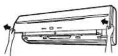
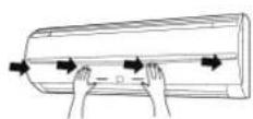
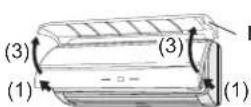
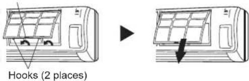
1. Remove the intake grille and the air filter.
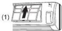
(1) Place your fingers at both lower ends of the grille panel, and lift forward.
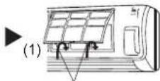
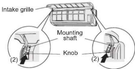
(2) Pull down the knob.
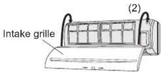
(3) Open the intake grille, and lift the intake grille upward, until the axle at the top of the intake grille is removed.
(4) Lift up the air filter's handle, disconnect the 2 lower tabs, and pull out the air filter.
Air fi Iter handle
Cleaning2.
(1) Cleaning the intake grill
Remove dust with a vacuum cleaner, wash the grille with warm water, and then dry with a clean and soft cloth.
(2) Cleaning the air fi liter
Remove dust with a vacuum cleaner or by washing. After washing, be sure to allow it to dry thoroughly in a shady place before reinstalling.
3. Replace the intake grille and the air filter.
(1) Align the sides of the air filter with the panel, and push in fully, making sure the 2 lower tabs are returned properly to their holes in the panel.
(2) The fixing axle of the intake grille is installed on the front panel.
(3) Lay down the intake grille.
Hooks (2 places)
▶
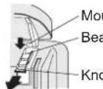
Mounting shaft
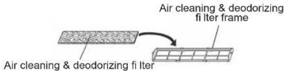
Air cleaning & deodorizing fi Iter installation
(1) Open the intake grille and remove the air filters.
(2) Set the Air cleaning & deodorizing filter into the Air cleaning & deodorizing filter frame.
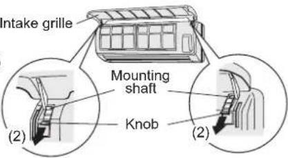
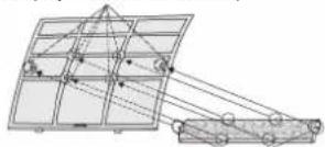
(3) Engage the 6 latches of the Air cleaning & deodorizing filter frame with the 6 hooks at the rear of the air filters.
(4) Install the 2 air filters and close the intake grille.
Hook (6 places at the rear)
natural_image
Technical line drawing of a mechanical assembly with grid and bracket components (no text or symbols)Latch (6 places)
Cleaning body
Wash the body with warm water, and then dry with a clean and soft cloth.
When not using for an extended period
Leave the breaker on for at least 12 hours before starting operation when it is to be used again.
The following conditions are not breakdowns or operation failures.
| Symptom Problem See page | |||
| Doesn't operate immediately: | If the unit is stopped and then immediately started again, the compressor will not operate for about 3 minutes, in order to prevent fuse blowouts.Whenever the electrical breaker is turned off then on again, the protection circuit will operate for about 3 minutes, preventing unit operation during that period. | — | |
| — | |||
| Airflow is weak or stops: | When Heating operation is started, indoor unit's fan may temporarily stop, to allow internal parts to warm up. | — | |
| During Heating operation, if the room temperature rises above the thermostat setting, the outdoor unit will stop, and the indoor unit's fan will stop. If you wish to warm the room further, set the thermostat for a higher setting. | — | ||
| During oil recovery operation, the airflow may stop for approximately 10 minutes. | 2 | ||
| During Heating operation, the unit will temporarily stop operation (between 4 and 15 minutes) as the Automatic Defrosting mode operates. | 2 | ||
| The fan may operate at low speed during Dry operation or when the unit is monitoring the room's temperature. | — | ||
| In the monitor AUTO operation, the fan will operate at low speed. — | |||
| Flashing lamps: The OPERATION indicator lamp (green) fl ashes: | An oil recovery operation is being performed. | 2 | |
| The OPERATION indicator lamp (green) fl ashes: | An automatic defrosting operation is being performed. | ||
| The OPERATION indicator lamp (green) and TIMER indicator lamp (orange) are fl ashing alternately: | It has recovered from a power outage. | ||
| The OPERATION indicator lamp (green) and TIMER indicator lamp (orange) are fl ashing simultaneously: | It is operating in trial operation mode.Ask a manager as there may be maintenance being conducted. | ||
| The OPERATION indicator lamp (green) lights up and the TIMER indicator lamp (orange) fl ashes: | This is the standby state. | ||
| Noise is heard: | In the following conditions there are sounds of water flowing from the indoor unit and the operation sound becomes loud. These are the sounds of the flowing of refrigerant.When operation startsWhen oil recovery operation fi nishesWhen automatic defrosting operation fi nishes | — | |
| During operation, a slight squeaking sound may be heard. This is the result of minute expansion and contraction of the panel due to temperature changes. | — | ||
| During Heating operation, a sizzling sound may be heard occasionally. This sound is produced by the Automatic Defrosting operation. | 2 | ||
| Smells: Some smell may be emitted from the indoor unit. This smell is the result of room smells (furniture, tobacco, etc.) which have been taken into the air conditioner. | — | ||
| Fog comes out of the indoor unit: | During Cooling operation, a thin mist may be seen emitted from the indoor unit. This results from the sudden Cooling of room air by the air emitted from the air conditioner, resulting in condensation and misting. | — | |
| Steam comes out of the indoor unit: | During Heating operation, the outdoor unit's fan may stop, and steam may be seen rising from the unit. This is due to the Automatic Defrosting operation. | 2 | |
| Water is produced from the outdoor unit: | During Heating operation, water may be produced from the outdoor unit due to the Automatic Defrosting operation. | — | |
The following conditions may not be breakdowns so check again.
| Symptom Items to check | See page | |
| Doesn't operate at all: Has there been a power failure? | — | |
| Has a fuse blown out, or a circuit breaker been tripped? | ||
| Is the main power switch set to the OFF position? | ||
| Are you trying to engage in an operation different from the priority state? | ||
| Is it in standby state? | ||
| The operation mode cannot be changed: | Are you trying to change to an operation different from the priority conditions? | 2 |
| Poor Cooling (or Heating) performance: | Did you adjust the room temperature settings (thermostat) correctly? | — |
| Is the air filter dirty? | 3 | |
| Are the air conditioner's inlet port or outlet port blocked? | — | |
| Is there a window or door open? | — | |
| In the case of Cooling operation, is a window allowing bright sunlight to enter? (Close the curtains.) | — | |
| In the case of Cooling operation, are there heating apparatus and computers inside the room, or are there too many people in the room? | — | |
| Is the fan speed set to low? | — | |
| Set the temperature lower than the room temperature and use it: | Temperature does not fall down well.Temperature may not fall down depending on the room conditions.(While high humidity or the room temperature is high.) | 3 |
In following situations stop operation immediately and get in touch with authorized service personnel.
The problem cannot be solved even when the troubleshooting checks have been performed.
- The OPERATION indicator lamp (green) is flashing very fast.
The wired remote controller or simple remote controller indicate Er (when connected).
It has burning smell.
SPECIFICATIONS
| MODEL | AS□E07GACH | AS□E09GACH | AS□E12GACH | AS□E14GACH | |
| POWER SOURCE 230 V ~ 50 Hz | |||||
| AVAILABLE VOLTAGE RANGE 198 to 264 V | |||||
| COOLING CAPACITY [kW] 2.2 2.8 3.6 4.5 | |||||
| HEATING CAPACITY [kW] 2.8 3.2 4.1 5.0 | |||||
| SOUND PRESSURE LEVEL | |||||
| HIGH dB [A] | 34 | 35 | 38 | 43 | |
| MED dB [A] | 32 | 32 | 34 | 35 | |
| LOW dB [A] | 30 | 30 | 30 | 30 | |
| DIMENSIONS & WEIGHT | |||||
| HEIGHT [mm] | 275 | ||||
| WIDTH [mm] | 790 | ||||
| DEPTH [mm] | 215 | ||||
| WEIGHT [kg] | 9 | ||||
| MODEL | AS☐A07GACH | AS☐A09GACH | AS☐A12GACH | AS☐A14GACH | |
| POWER SOURCE 230 V ~ 50 Hz | |||||
| AVAILABLE VOLTAGE RANGE 198 to 264 V | |||||
| COOLING CAPACITY [kW] 2.2 2.8 3.6 4.5 | |||||
| HEATING CAPACITY [kW] 2.8 3.2 4.1 5.0 | |||||
| SOUND PRESSURE LEVEL | |||||
| HIGH dB [A] | 35 | 36 | 39 | 44 | |
| MED dB [A] | 33 | 33 | 35 | 37 | |
| LOW dB [A] | 31 | 31 | 31 | 32 | |
| DIMENSIONS & WEIGHT | |||||
| HEIGHT [mm] | 275 | ||||
| WIDTH [mm] | 790 | ||||
| DEPTH [mm] | 215 | ||||
| WEIGHT [kg] | 9 | ||||
- Acoustic Noise Information: The maximum sound pressure level is less than 70 dB (A) for both indoor unit and outdoor unit.
According IEC 704-1 and ISO 3744.
BEDIENUNGSANLEITUNG
TEIL NR. 9377772084
natural_image
Diagram of a car air conditioner unit with arrows indicating airflow direction (no text or symbols)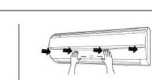
natural_image
Illustration of hands holding a cylindrical object with arrows indicating motion (no text or symbols)natural_image
Diagram showing two views of an air conditioner unit before and after installation, with no text or symbols present.Crochets (2 emplacements)
Nettoyage2.
natural_image
Technical line drawing of a mechanical lifting device with grid and pulley components (no text or symbols)Loquet (6 emplacements)
Nettoyage du corps
natural_image
Illustration of hands holding a cylindrical object with arrows indicating direction (no text or symbols)natural_image
Pure geometric diagram of a grid structure with connected lines and circles, no text or symbols presentFermi (6 punti)
Pulizia del corpo
natural_image
Illustration of hands holding a cylindrical object with arrows indicating direction (no text or symbols)natural_image
Technical line drawing of a mechanical assembly with grid and pulley components (no text or symbols)Μάνδαλο (6 θέσεις)
Καθαρισμός μονάδας
natural_image
Technical line drawing of a mechanical assembly with grid and pulley components (no text or symbols)Lingueta (6 locais)
natural_image
Diagram showing airflow or ventilation system before and after installation, with no text or symbols presentnatural_image
Diagram of a mechanical or optical setup with grid panels and connected beams (no text or symbols)natural_image
Technical line drawing of a mechanical assembly with pulleys and components (no text or symbols)المزالج (6Amakn)
تنظيف الهيكل
natural_image
Line drawing of a cylindrical air conditioner unit with two horizontal panels and ventilation slots (no text or symbols)ASYE07GACH / ASHE07GACH
ASYE09GACH / ASHE09GACH
ASYE12GACH / ASHE12GACH
ASYE14GACH / ASHE14GACH
ASYA07GACH / ASHA07GACH
ASYA09GACH / ASHA09GACH
ASYA12GACH / ASHA12GACH
ASYA14GACH / ASHA14GACH