
GXSHC40N - Water Softener Café - Free user manual and instructions
Find the device manual for free GXSHC40N Café in PDF.

| Product Type | Ion exchange resin water softener |
| Brand | Café |
| Model | GXSHC40N |
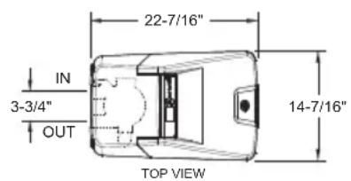
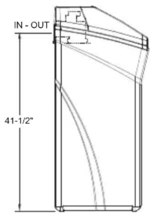
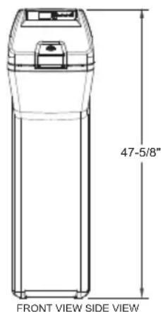
| Dimensions (L x D x H) | 22.4 in x 14.4 in x 47.6 in (57 cm x 36.6 cm x 121 cm) |
| Power supply | 120 V, 60 Hz via included external 24 V transformer |
| Nominal capacity | Up to 40,000 grains (depending on salt dose) |
| Nominal salt efficiency | 5,090 grains/lb salt (at minimum dose) |
| Service flow rate | 9.5 gal/min (36 L/min) |
| Resin tank volume | 1.11 ft³ (31.4 L) |
| Maximum incoming water hardness | 110 grains/gal |
| Maximum dissolved iron | 8 ppm |
| Required water pressure | 20 to 125 psi (1.4 to 7.0 kg/cm²) |
| Allowable water temperature | 40 to 120 °F (4 to 49 °C) |
| Regeneration | Automatic on-demand (AOD), scheduled at 2 am (adjustable) |
| Main functions | Softening, ferrous iron removal, automatic bypass during recharge, Wi-Fi connectivity, motorized shut-off valve |
| Maintenance and cleaning | Cleaning of nozzle-venturi assembly, breaking salt bridges, adding salt, periodic disinfection |
| Safety | Mandatory grounding, do not use with non-potable water without disinfection, salt cover always in place |
| Spare parts and repairability | Detailed parts list available (exploded view), 1 year parts and labor warranty, 3 years on valving, 10 years on tank |
| General information | Certified NSF/ANSI 44, CSA B483.1; reduces barium and radium; transformer and bypass valve included |
| Country of origin | Not specified in the manual |
Frequently Asked Questions - GXSHC40N Café
User questions about GXSHC40N Café
0 question about this device. Answer the ones you know or ask your own.
Ask a new question about this device
Download the instructions for your Water Softener in PDF format for free! Find your manual GXSHC40N - Café and take your electronic device back in hand. On this page are published all the documents necessary for the use of your device. GXSHC40N by Café.
USER MANUAL GXSHC40N Café
WATER SOFTENING SYSTEM
Safety Information 2
Specifications
and Performance Claims ..... 3
About the Softener 4
Before you Start 7
Installation Requirements ..... 8
Installation Instructions ..... 11
Programming the Softener ..... 18
Care and Cleaning 25
Routine Maintenance ..... 27
Before you call for Service ..... 28
Exploded View/Parts List ..... 3 4
Warranty (U.S.) 42
Warranty (Canada) 43
Consumer Support ..... 4 4
OWNER'S MANUAL AND INSTALLATION INSTRUCTIONS
Model GXSHC40N
ENGLISH/FRANÇAIS/ ESPAÑOL
Write the model and serial numbers here:
Model #
Serial # ____
To find these numbers, lift the cover and look on the rim below the control panel.

Systems tested and certified by NSF International against NSF/ANSI Standard 44 and certified to NSF/ANSI/CAN 372.
Systems Tested and Certified by the Water Quality Association against CSA B483.1.
If you have any questions or concerns when installing or maintaining your water softener, call our toll free number at 800-952-5039 (US) or 866-777-7627 (Canada), or visit GEAppliances.com. When you call, please be prepared to provide the model and serial number of your product. This information can be found on the rating decal located on the rim under the salt cover.
GE is a trademark of the General Electric Company. Manufactured under trademark license.
IMPORTANT SAFETY INFORMATION. READ ALL INSTRUCTIONS BEFORE USING
SAFETY PRECAUTIONS
WARNING
For your safety, the information in this manual must be followed to minimize the risk of electric shock, property damage or personal injury.
WARNING
A copper or
galvanized cold water pipe may be used to ground electrical outlets in the home. Failure to maintain this ground path may result in an electric shock hazard. If the cold water pipe is used to ground electric outlets, please refer to Installing the Ground Wire section before cutting the pipe.
- Check and comply with your state and local codes. You must follow these guidelines.
- Use care when handling the water softening system. Do not turn upside down, drop, drag or set on sharp protrusions.
Water softening systems using sodium chloride (salt) for recharge add sodium to the water.
Persons on sodium restricted diets should consider the added sodium as part of their overall intake. Potassium chloride can be used as an alternative to sodium chloride in your softener. - Use only lead-free solder and flux for all sweat-solder connections, as required by state and federal codes.
This water softening system must be properly installed and located in accordance with the installation instructions before it is used. - Keep the salt hole cover in place on the softener unless servicing the unit or refilling with salt.
In the state of California: You must turn the Salt Efficiency feature setting to ON. This may initiate more frequent recharges. However it will operate at 4,000 grains per pound of salt or higher. To turn on the Salt Efficiency feature, follow the instructions in the “Salt Efficiency” section of this manual.
WARNING
Do not use with
water that is microbiologically unsafe or of unknown quality without adequate disinfection before or after the system.
WARNING
Discard all unused
parts and packaging material after installation. Small parts remaining after the installation could be a choke hazard.
The water softening system works on 24 volt-60 Hz electrical power only. Be sure to use the included external power supply.
■ External power supply must be plugged into an indoor 120 volt, grounded outlet only.
Use clean water softening salts only, at least 99.5% pure. NUGGET, PELLET or coarse SOLAR salts are recommended. Do not use rock, block, granulated or ice cream making salts. These types of salts may contain dirt and sediments that might mush or cake, creating maintenance issues for the water softener.
- Avoid installing in direct sunlight. Excessive heat may cause distortion or other damage to non-metallic parts.
If installing the water softener outdoors, do not locate where it will be exposed to wet weather, direct sunlight, extreme hot or cold temperatures, or other forms of abuse.
In the Commonwealth of Massachusetts, Plumbing Code 248 CMR shall be adhered to. Consult with your licensed plumber.
Specifications and Performance Claims
This model is efficiency rated. The efficiency rating is valid only at the minimum stated salt dose. The softener has a demand initiated regeneration (D.I.R) feature that complies with specific performance specifications intended to minimize the amount of regenerant brine and water used in its operation.
The softener has a rated salt efficiency of not less than 4,000 grains of total hardness exchange per pound of salt (based on sodium chloride), and shall not deliver more salt than its listed rating or be operated at a sustained maximum service flow rate greater than its listed rating. This softener has been proven to deliver soft water for at least ten continuous minutes at the rated service flow rate. The rated salt efficiency is measured by laboratory test described in NSF/ANSI Standard 44. These tests represent the maximum possible efficiency that the system can achieve. Operational efficiency is the actual efficiency after the system has been installed. It is typically less than the efficiency, due to individual application factors including water hardness, water usage, and other contaminants that reduce the softener's capacity.
| Specifications | |
| Model GXSHC40N | |
| Rated Capacity* (Grains@ Salt Dose) 11,700 @ 2.3 lbs | 31,500 @ 8.7 lbs.40,000 @ 15.1 lbs. |
| Rated Efficiency** (Grains/Pound of Salt @ Minimum Salt Dose) 5,090 @ 2.3 lbs. | |
| Water used during Regeneration (gallons/grains) 2.7 /1000 | |
| Total Water Used per Regeneration @ Maximum Salt Dose 37.0 gallons | |
| Amount of High Capacity Ion Exchange Resin (lb/cu.ft.) 57.56/1.11 | |
| Resin Tank Nominal Size (in., dia. x height) 9 x 40 | |
| Service Flow Rate (gpm) 9.5 | |
| Pressure Drop at Rated Service Flow (psig) 12.7 | |
| Water Supply Maximum Hardness (gpg) 110 | |
| Water Supply Maximum Clear Water Iron (ppm)*** 8 | |
| Water Pressure Limits (minimum-maximum psi)**** 20-125 | |
| Water Temperature Limits (minimum-max. °F) 40-120 | |
| Maximum Flow Rate to Drain (gpm) | 2.3 |
These systems conform to NSF/ANSI 44 for the specific capacity claims as verified and substantiated by test data.
* Testing was performed using pellet grade sodium chloride as the regenerant salt.
** Efficiency rating is valid only at the lowest stated salt dosage. These softeners were efficiency rated according to NSF/ANSI 44.
*** Extent of iron removal may vary with conditions. The capacity to reduce clear water iron is substantiated by WQA test data. State of
Wisconsin requires additional treatment if water supply contains greater than 5 ppm clear water iron. Refer to Cleaning Iron Out of the Water Softening System section.
**** Canada working pressure limits: 1.4–7.0 kg/cm².
| Performance Claims | ||
| Contaminant | Influent Challenge Level | Maximum Allowable Product Water Level |
| Barium | 10 ±10% mg/L | 2.0 mg/L |
| Radium 226/228 | 25 pCi/L | 5pCi/L |
Test parameters include: pH = 7.5±0.5, flow rate = 7.5 gpm
and dynamic pressure = 35±5 psig
About the water softener system
SERVICE
When the water softening system is providing soft water, it is called “Service.” During service, hard water flows from the house main water pipe into the water softening system. Inside the water softening system resin tank is a bed made up of thousands of tiny, plastic resin beads. As hard water passes through the bed, each bead attracts and holds the hard minerals. This is called ion-exchanging. It is much like a magnet attracting and holding metals. Water without hard minerals (soft water) flows from the water softening system and to the house pipes.
After a period of time, the resin beads become coated with hard minerals and they have to be cleaned. This cleaning is called recharge. Recharge is started at 2:00 AM (factory setting) by the water softening system control, and consists of five stages or cycles. These are FILL, BRINING, BRINE RINSE, BACKWASH and FAST RINSE.
AUTOMATIC HARD WATER BYPASS DURING RECHARGE
During recharge the water softener is automatically put in bypass mode allowing hard water to be available to the home. Once the softener is recharged water is directed back through the softener to be conditioned.
However, you should avoid using HOT water because the water heater will fill with the hard water.
FILL
Salt dissolved in water is called brine. Brine is needed to clean the hard minerals from resin beads. To make the brine, water flows into the salt storage area during the fill stage.
BRINING
During brining, brine travels from the salt storage area into the resin tank. Brine is the cleaning agent needed to remove hard minerals from the resin beads. The hard minerals and brine are discharged to the drain.
The nozzle and venturi create a suction to move the brine, maintaining a very slow rate to get the best resin cleaning with the least salt.
BRINE RINSE
After a pre-measured amount of brine is used, the brine valve closes. Water continues to flow in the same path as during brining, except for the discontinued brine flow. Hard minerals and brine flush from the resin tank to the drain.
BACKWASH
During backwash, water travels up through the resin tank at a fast flow rate, flushing accumulated iron, dirt and sediments from the resin bed and to the drain.
FAST RINSE
Backwash is followed by a fast flow of water down through the resin tank. The fast flow flushes brine from the bottom of the tank, and packs the resin bed.
After fast rinse, the water softening system returns to soft water service.
About the water softener system
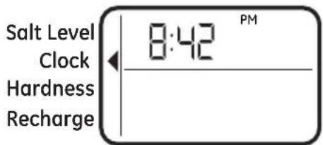
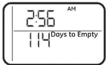
NORMAL OPERATION, CONTROL DISPLAYS
During normal operation, the present time of day and AM or PM and DAYS TO EMPTY show in the control display area.
The system will automatically recharge at the preset recharge time as needed.
FEATURE: OPTIONAL RECHARGE CONTROLS
Sometimes, a manually started recharge may be desired or needed. Two examples:
- You have used more water than usual (house guests, extra washing, etc.) and you may run out of soft water before the next recharge.
The system ran out of salt.
Use one of the following features to start a recharge immediately, or at the next preset recharge start time.
RECHARGE TONIGHT
Touch (do not hold) the RECHARGE button. RECHARGE TONIGHT flashes in the control display area. A recharge will occur at the next preset recharge start time. If you decide to cancel this recharge, touch the same button once more.
RECHARGE NOW
Press and hold the RECHARGE button until RECHARGE NOW starts to flash in the control display area. The water softening system begins an immediate recharge and, when over in about two hours, you will have a new supply of soft water. Once started, you cannot cancel this recharge.
FEATURE: MEMORY
If electrical power to the water softening system is interrupted, the control display is blank, and the blue indicator light is off, but the control keeps correct time for 24 hours. When power is restored, you have to reset the present time only if the display and blue indicator light are flashing. All other settings are maintained and never require resetting unless a change is desired.
If the time is flashing after a long power outage, the water softening system continues to work as it should to provide you with soft water. However, recharge may occur at the wrong time of day until you reset the control to the correct time of day.
FEATURE/SERVICE: AUTOMATIC ELECTRONIC DIAGNOSIS
The control computer has a self-diagnostic function for the electrical system (except input power and water meter). The computer monitors the electronic components and circuits for correct operation. If a malfunction occurs, an error code appears in the control display.
WATER CONDITION INFORMATION IRON
Iron in water can cause stains on clothing and plumbing fixtures. It can negatively affect the taste of food, drinking water, and other beverages. Iron in water is measured in parts per million (ppm). The total* ppm of iron, and type or types*, is determined by chemical analysis. Four different types of iron in water are:
■ Ferrous (clear water) iron
- Ferric (red water) iron
■ Bacterial and organically bound iron
■ Colloidal and inorganically bound iron (ferrous or ferric)
Ferrous (clear water) iron is soluble and dissolves in water. This water softener will reduce moderate amounts of this type of iron (see specifications).**Ferrous (clear water) iron is usually detected by taking a sample of water in a clear bottle or glass. Immediately after taking, the sample is clear. As the water sample stands, it gradually clouds and turns slightly yellow or brown as air oxidizes the iron. This usually occurs in 15 to 30 minutes.
When using the softener to reduce Ferrous (clear water) iron, add 5 grains to the hardness setting fore very 1 ppm of Ferrous (clear water) iron. See “Set Water Hardness Number” section.
Ferric (red water), and bacterial and organically bound irons are insoluble. This water softener will not remove ferric or bacterial iron. This iron is visible immediately when drawn from a faucet because it has oxidized before reaching the home. It appears as small cloudy yellow, orange, or reddish suspended particles. After the water stands for a period of time, the particles settle to the bottom of the container. Generally these irons are removed from water by filtration. Chlorination is also recommended for bacterial iron.
Colloidal and inorganically bound iron is of ferric or ferrous form that will not filter or exchange out of water. This water softener will not remove colloidal iron. In some instances, treatment may improve colloidal iron water. Colloidal iron water usually has a yellow appearance when drawn. After standing for several hours, the color persists and the iron does not settle, but remains suspended in the water.
SEDIMENT FILTER (BUILT IN)
Sediment is fine, foreign material particles suspended in water. This material is most often clay or silt. Extreme amounts of sediment may give the water a cloudy appearance. The built in sediment filter keeps larger particles of sediment from entering the home plumbing system. As water passes through the softener, the larger sediment particles are collected in the integrated basket and then rinsed to the drain before each regeneration. The sediment filter feature provides added protection for water using appliances by reducing the chance of larger particles entering the various products valves and screens.
IMPORTANT: The sediment filter is not intended to replace pretreatment filtration. For problem water applications, additional sediment filtration is recommended.
CHLORINE
Softener resins may degrade in the presence of chlorine above 2 ppm. If you have chlorine in excess of this amount, you may experience reduced life of the resin. In these conditions, you may wish to consider purchasing a GE Appliances point-of-entry household filtration system with a chlorine reducing filter.
* Water may contain one or more of the four types of iron and any combination of these.
Total iron is the sum of the contents.
** Capacity to reduce clear water iron is substantiated by WQA test data.
BEFORE YOU START
The water softener requires a minimum water flow of 3 gallons per minute at the inlet. Maximum allowable inlet water pressure is 125 psi. If daytime pressure is over 80 psi, nighttime pressure may exceed the maximum. Use a pressure reducing valve if necessary (Adding a pressure reducing valve may reduce the flow). If your home is equipped with a back flow preventer, an expansion tank must be installed in accordance with local codes and laws.
The water softener uses a direct plug-in external power supply (included). Be sure to use the included power supply and plug it into a nominal 120V, 60 cycle household outlet that is in a dry location only, grounded and properly protected by an over current device such as a circuit breaker or fuse.
■ WiFi communication requires WiFi connectivity and electrical power at the location of the softener. App connectivity will not function should either fail. (Check for both before the system is fully installed.)
Do not use this system to treat water that is microbiologically unsafe or of unknown quality without adequate disinfection upstream or downstream of the system.
TOOLS AND MATERIALS REQUIRED FOR INSTALLATION
Pliers
Screwdriver
Razor knife
■ Two adjustable wrenches
Teflon tape
2 fittings to connect household plumbing to 1" NPT threads on softening adaptors.
■ Additional installation parts may be required:
- UL-approved grounding clamps and 6-gauge copper grounding wire.
INSPECT SHIPMENT
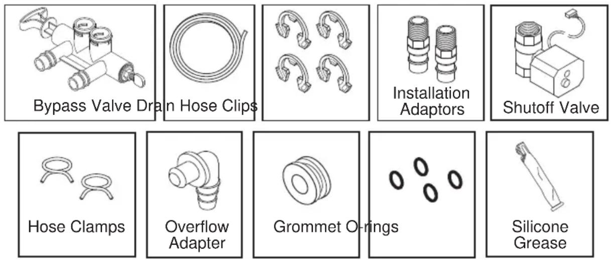
Make sure all the parts shown below are present. Additional parts must be purchased to complete the installation. Thoroughly check the water softener for possible shipping damage and parts loss. Also inspect and note any damage to the shipping carton.
Remove and discard (or recycle) all packing materials. To avoid loss of small parts, we suggest you keep the small parts in the parts bag until you are ready to use them.

Discard all unused parts and packaging material after installation. Small parts remaining after the installation could be a choke hazard.
NOTE: Failure to comply with these installation instructions will void the product warranty, and the installer will be responsible for any service, repair or damages caused thereby.
LOCATION REQUIREMENTS
Consider all of the following when selecting an installation location for the water softener.
Do not locate the water softener where freezing temperatures occur. Do not attempt to treat water over 120^ F. Freezing temperatures or hot water damage voids the warranty.
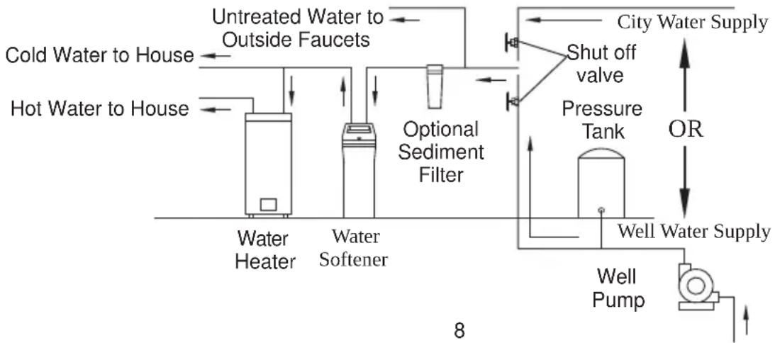
To condition all water in the home, install the water softener close to the water supply inlet, and upstream of all other plumbing connections, except outside water pipes. Outside faucets should remain on hard water to avoid wasting conditioned water and salt.
A nearby drain is needed to carry away regeneration discharge (drain) water. Use a floor drain, laundry tub, sump, standpipe, or other options(check your local codes). See “Air Gap Requirements” and “Valve Drain Requirements” sections.
The water softener uses a direct plug-in external power supply (included). Be sure to use the included power supply and plug it into a nominal 120V, 60 cycle household outlet that is in a dry location only, grounded and properly protected by an over current device such as a circuit breaker or fuse.
■ Always install the water softener between the water inlet and water heater. Any other installed water conditioning equipment should be installed between the water inlet and water softener (See Figure below).
If installing the water softener outdoors, do not locate where it will be exposed to wet weather, direct sunlight, extreme hot or cold temperatures, or other forms of abuse.
■ DO NOT RUN HOT WATER THROUGH THE SOFTENER. Temperature of water passing through the softener must be less than 120^ F.
- Avoid installing in direct sunlight. Excessive sun heat may cause distortion or other damage to non-metallic parts.
- When installing in an outside location you must take steps necessary to assure the softener, installation plumbing and wiring, are protected from the elements, direct sunlight, contamination, vandalism, insects, vermin, etc.
- Do not install the softener where it would block access to the water heater or access to the main water shutoff.
DIMENSIONS
PROPER ORDER TO INSTALL WATER TREATMENT EQUIPMENT
flowchart
graph LR
    A["Hot Water to House"] --> B["Water Heater"]
    C["Cold Water to House"] --> D["Water Softener"]
    E["Untreated Water to Outside Faucets"] --> F["Optional Sediment Filter"]
    G["City Water Supply"] --> H["Shut off valve"]
    H --> I["Pressure Tank"]
    I --> J["Well Pump"]
    J --> K["Well Water Supply"]
    L["OR"] --> M["Well Water Supply"]
    N["8"] --> O["Water Heater"]
    N --> P["Water Softener"]
PLUMBING CODES
All plumbing must be completed in accordance with national, state and local plumbing codes. In the state of Massachusetts: The Commonwealth of Massachusetts plumbing code 248-CMR shall be adhered to. A licensed plumber shall be used for this installation.
AIR GAP REQUIREMENTS
A drain is needed for regeneration water (See Figure 1). A floor drain, close to the water softener, is preferred. A laundry tub, standpipe, etc. are other drain options. Secure valve drain hose in place. Leave an air gap of 1-1/2" between the end of the hose and the drain. This gap is needed to prevent back flow of sewer water into the water softener. Do not put the end of the drain hose into the drain.
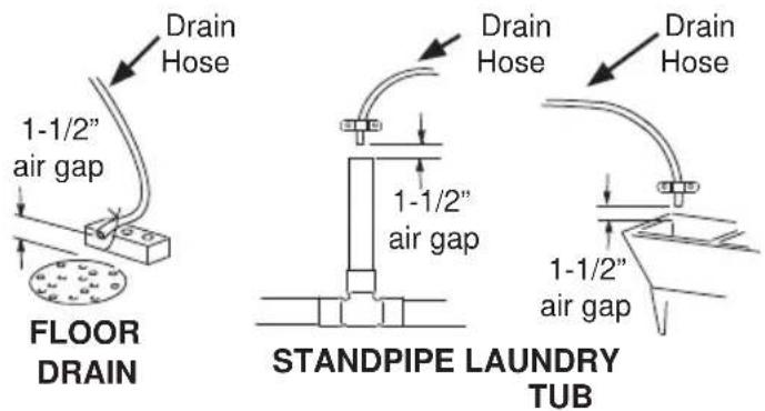
Figure 1
VALVE DRAIN REQUIREMENTS
Using the flexible drain hose (included) (See Figure 2), measure and cut to the length needed. Flexible drain hose is not allowed in all localities (check your plumbing codes). If local codes do not allow use of a flexible drain hose, a rigid valve drain run must be used. Purchase a compression fitting (1/4 NPT x 1/2 in. minimum tube) and 1/2" tubing from your local hardware store. Plumb a rigid drain as needed (See Figure 3).
NOTE: Avoid drain hose runs longer than 30 feet. Avoid elevating the hose more than 8 feet above the floor. Make the valve drain line as short and direct as possible.
FLEXIBLE DRAIN LINE
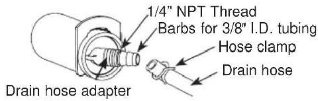
Figure 2
RIGID DRAIN LINE
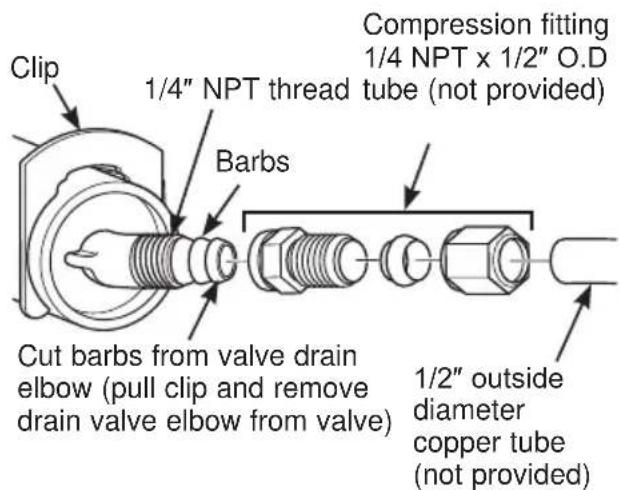
Figure 3
INLET/OUTLET PLUMBING REQUIREMENTS
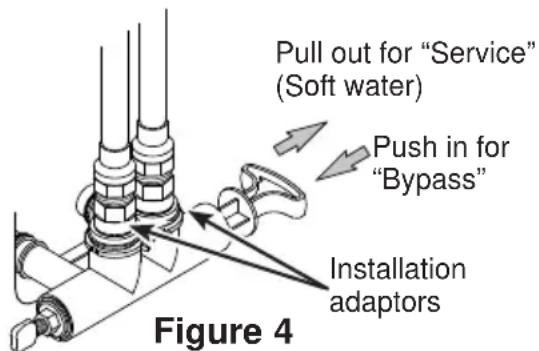
Always install either a single bypass valve (provided), as shown in Figure 4, or, if desired, parts for a 3 valve bypass system (not included) can be purchased and assembled, as shown in Figure 5. Bypass valves allow you to turn off water to the softener for maintenance if needed, but still have water in house pipes.
Pipe fittings must be 1/2" minimum.
Use:
Copper pipe
Threaded pipe
■ PEX (Crosslinked Polyethylene) pipe
CPVC plastic pipe
- Other pipe approved for use with potable water
IMPORTANT: Do not solder with plumbing attached to installation adaptors and single bypass valve. Soldering heat will damage the adaptors and valve.
SINGLE BYPASS VALVE
WARNING
A copper or
galvanized cold water pipe may be used to ground electrical outlets in the home. Failure to maintain this ground path may result in an electric shock hazard. If the cold water pipe is used to ground electric outlets, please refer to Installing the Ground Wire section before cutting the pipe.
3-VALVE BYPASS SYSTEM
For soft water service: Open the inlet and outlet valves and close the bypass valve.
For bypass hard water: Close the inlet and outlet valves and open the bypass valve.
3 VALVE BYPASS
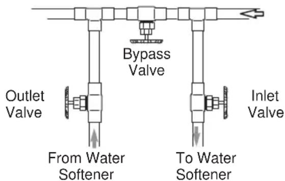
Figure 5
Installation Instructions
TYPICAL INSTALLATION
| Clamp(not included) | Ground Wire(not included) | 1" NPTMThreadedAdaptor (notincluded) | Pipe | |
| Hard Waterto OutsideFaucets | ConditionedWater | |||
| Main Water Pipe | ||||
| IncomingHard Water | TopCover | Plug intocontroller | 1" NPTFSweatAdaptor(notincluded) | |
| Plug-inTransformer | Motorized WaterShutoff valve | |||
| Clips | 1" NPTMThreadedAdaptorO-ring | |||
| ToController | Outlet | |||
| OverflowAdapter | Inlet | |||
| Drain HoseAdapter | Brine TankOverflow Hose* | |||
| Valve DrainHose* | LubricatedO-ring | |||
| Brine Tank(Salt Storage) | Clips | Single BypassValveFigure 7 | ||
| Secure Valve DrainHose in place over FloorDrain | ||||
| *Do not connect the watersoftener valve drain hose tothe brine tank overflow | Floor Drain | 1-1/2"air gapNOTE: See "Air Gap Requirements" section. | ||
Figure 6
- Remove plastic shipping plug and wire from valve outlet.
Turbine
Valve outlet
Plastic shipping plug
Turbine shaft and support
Figure 8
NOTE: Be sure the turbine and support are firmly in place in the valve outlet. Blow into the valve port and observe the turbine for free rotation.
TURN OFF WATER SUPPLY
- Close the main water supply valve, located near the well pump or water meter.
- Open all faucets to drain all water from house pipes.
NOTE: Be sure not to drain water from the water heater, as damage to the water heater elements could result.
INSTALL BRINE TANK OVERFLOW ADAPTER
Install the brine tank overflow grommet and adapter in the 13/16" diameter hole in the back of the salt storage tank sidewall, (see Figure 9).
NOTE: The brine tank overflow adapter accepts either 1/2" or 3/8" I.D. hose.
INSTALL THE BYPASS VALVE
NOTE: For easier installation, remove the top cover. Release 2 clips at rear of cover. Rotate cover forward and lift up.
- Remove two clips from the water softener valve inlet and outlet ports and visually check and remove any debris, (see Figure 7).
- Make sure the turbine assembly spins freely in the "out" port of the valve, (see Figure 8).
- If not already done, put a light coating of silicone grease (provided) on the single bypass valve o-rings, (see Figure 7).
- Push the single bypass valve into the softener valve as far as it will go. Snap the two large holding clips into place, from the top down, (see Figure 7 and 10).
IMPORTANT: Be sure the clips snap firmly into place so the single bypass valve will not pull out.
MOVE WATER SOFTENER INTO PLACE

Excessive Weight Hazard
Use two or more people to move and install water softener. Failure to do so can result in back or other injury.
- Move the water softener into the desired location. Set it on a solid, level surface.
IMPORTANT: Do not place shims directly under the salt storage tank to level the softener. The weight of the tank, when full of water and salt, may cause the tank to fracture at the shim.
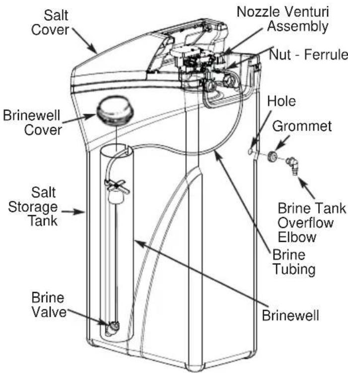
Figure 9
NOTE: Unit is shown with top cover removed.
SINGLE BYPASS VALVE
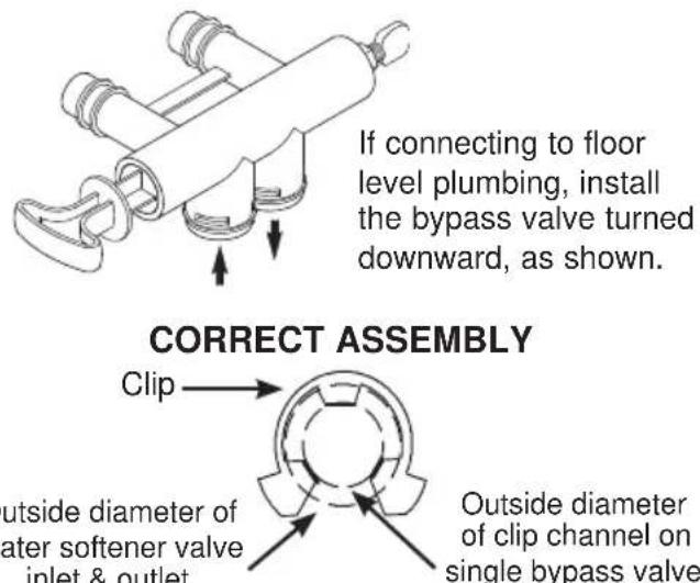
Figure 10
NOTE: Be sure all 3 tabs of the clip go through the matching holes on the water softener valve inlet or outlet, and fully into the channel on the single bypass valve. Make sure that the tabs are fully seated.
Installation Instructions
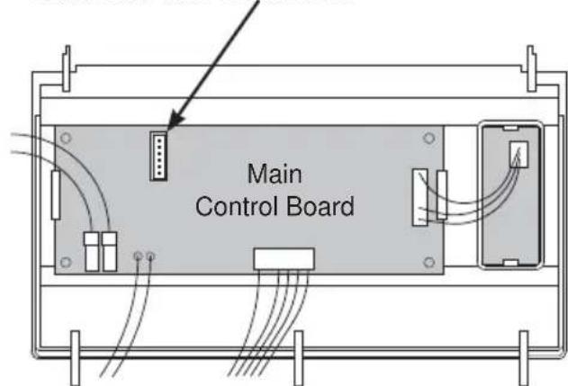
GETTING ACCESS TO MAIN CONTROL BOARD
(TO PLUG IN WATER SHUTOFF VALVE)
INSTALL MOTORIZED WATER SHUTOFF VALVE
Install the included water shutoff valve on the threaded installation adapter leading to the water softener's INLET. Optionally, it may be installed elsewhere in the plumbing upstream of the water softener inlet, making sure that the 10 foot long cable will reach the water softener's main control board (see illustration). The shutoff valve's inlet and outlet are female 1" NPT. Support the weight of the shutoff valve.
After completing plumbing, make sure that the water softener is not powered up, and plug the cable from the shutoff valve into the corresponding connector on the main control board (see illustration at right).
NOTE: The shutoff valve may be operated manually by pulling out and turning the knob on the shutoff valve body, although there is no need to do this when installing.
CAUTION
Do not place fingers into the motorized shutoff valve
when it is plugged into the electronic controller.
- Pull out both tabs on back of the top cover to unlock cover.
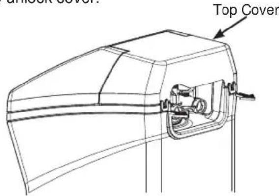
- Tilt top cover upward and lift off.
- Open salt lid and tilt back until is rests.
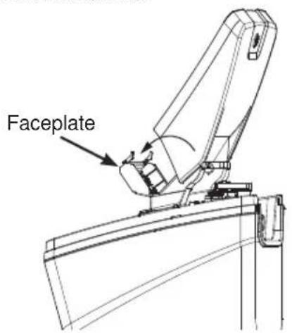
- Pull both tabs toward center to unlock faceplate.
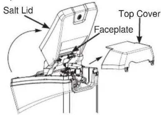
- Tilt faceplate forward to expose back of the control board.
Installation Instructions
- With power off, plug the shutoff valve's cable into this connector.
Back of Faceplate Assembly
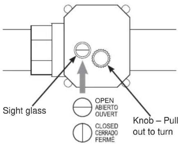
MOTORIZED WATER SHUTOFF VALVE
To manually operate the motorized water shutoff valve, pull out the round knob on the valve and turn it until the red line in the sight glass matches the desired (open or closed) position. See illustration below.
Motorized Water Shutoff Valve
COMPLETE INLET AND OUTLET PLUMBING
WARNING
A copper or
galvanized cold water pipe may be used to ground electrical outlets in the home. Failure to maintain this ground path may result in an electric shock hazard. If the cold water pipe is used to ground electric outlets, please refer to Installing the Ground Wire section before cutting the pipe.
IMPORTANT: This water softener has a non-metallic valve system. Installing it on metal plumbing will break electrical continuity, which may interrupt grounding for the home. You must restore electrical continuity in your metal plumbing system.
If you install a 3-valve bypass system (Figure 5), electrical continuity will be maintained. If you install the non-metallic bypass valve (Figure 11), please refer to the Installing the Ground Wire section before cutting the pipe.
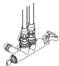
natural_image
Technical line drawing of a mechanical assembly with multiple cylindrical components and a handle (no text or symbols)Figure 11
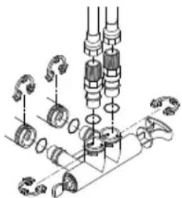
natural_image
Mechanical assembly diagram showing gears and shafts in a mechanical assembly (no text or labels)Measure, cut, and loosely assemble pipe and fittings from the main water pipe to the inlet and outlet ports of the water softener valve. Be sure to keep fittings fully together, and pipes squared and straight.
BE SURE INCOMING HARD WATER SUPPLY IS DIRECTED TO THE SOFTENER VALVE INLET PORT.
NOTE: Inlet and outlet are marked on the water softener valve. Trace the water flow direction to be sure hard water is to inlet.
IMPORTANT: Be sure to fit, align and support all plumbing to prevent putting stress on the water softener valve inlet and outlet. Stress from misaligned or unsupported plumbing may cause damage to the valve.
- If making a soldered copper installation, do all sweat soldering before connecting pipes to the NPT adapters and bypass valve. Torch heat will damage plastic parts.
WARNING
If solder is used to
make pipe connection use only lead free solder and flux to prevent lead poisoning.
- When turning threaded pipe fittings onto plastic fittings, use care not to cross-thread.
- Use Teflon Tape on all external pipe threads. Complete the inlet and outlet plumbing for the type of pipe you will be using. Secure ground clamp to metal pipes.
INSTALLING THE GROUND WIRE
NOTE: If your house plumbing is plastic, it would not be used as a grounding path, and this step should be skipped.
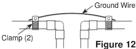
IMPORTANT: A copper or galvanized cold water pipe is often used to ground electrical outlets in the home. Grounding protects you from electrical shock. The water softener may have broken this ground path. To restore connection, install a 12"-long, 6-gauge copper wire across and tightly clamp using UL-approved 1/2"-1" bronze grounding clamps at both ends as shown (Figure 12). Zinc clamps should not be used on copper plumbing. Wire and clamps may be purchased separately from your local hardware store.
- Clean copper pipe and ends of wire with emery paper. Bare wire is recommended. If insulated wire is used, is should be stripped 3/4" at each end before cleaning with emery paper.
- Attach bronze clamps to pipe. Tighten screws.
- Attach to clamps as shown. Tighten screws.
NOTE: If you are installing a sediment filter or other item(s) into the plumbing system, along with the water softener, be sure to restore electrical continuity across all removed metal pipe sections.
INSTALL VALVE DRAIN HOSE
- Measure and connect the 3/8"drain line (provided) to the water softener valve drain fitting. Use a hose clamp to hold the hose in place.
NOTE: Avoid drain hose runs longer than 30 feet. Avoid elevating the hose more than 8 feet above the floor. Make the valve drain line as short and direct as possible.
IMPORTANT: If codes require a rigid drain line see "Valve Drain requirements" section.
-
Route the drain hose or copper tubing to the floor drain or other suitable drain point. Secure drain hose. This will prevent "whipping" during regenerations. See "Air Gap Requirements" section (Figure 1).
-
Cut and secure the hose.
NOTE: The softener will not work if the water cannot exit the drain hose during recharge.
INSTALL BRINE TANK (SALT STORAGE) OVERFIOW HOSE
- Measure, cut to needed length and connect the 3/8"drain line (provided) to the salt storage tank overflow elbow and secure in place with a hose clamp.
- Route the hose to the floor drain, or other suitable drain point no higher than the drain fitting on the salt storage tank (This is a gravity drain). If the tank overfills with water, the excess water flows to the drain point. Cut the drain line to the desired length and route it neatly out of the way.
IMPORTANT: For proper operation of the water softener, do not connect the water softener valve drain tubing to the salt storage tank overflow hose.
RINSE OUT CARBON FINES
Small particles of carbon filtration material are generated during manufacturing and shipping. These particles will exit the media tank with the first water that flows through the softener. These carbon “fines” are not harmful, but give the water a gray color and should be rinsed down the drain before any water from the softener is directed to the home’s faucets or water heater.
TEST FOR LEAKS
To prevent air pressure in the water softener and plumbing system, complete the following steps in order:
- Fully open two or more softened cold water faucets close to the water softener, located down stream from the water softener.
- Place the bypass valve (single or 3 valve) into the "bypass" position (see Figures 4 or 5).
-
Slowly open the main water supply valve. Run water until there is a steady flow from the opened faucets, with no air bubbles.
-
Place bypass valve(s) in "service" or soft water position as follows:
-
Single bypass valve (Figure 4): Slowly move the valve stem toward “service,” pausing several times to allow the water softener to fill with water.
-
3 valve bypass (Figure 5): Fully close the bypass valve and open the outlet valve. Slowly open the inlet valve, pausing several times to allow the water softener to fill with water.
-
After about three minutes, open a hot water faucet until there is a steady flow and there are no air bubbles, then close this faucet.
-
Close all cold water faucets and check for leaks at the plumbing connections that you made.
-
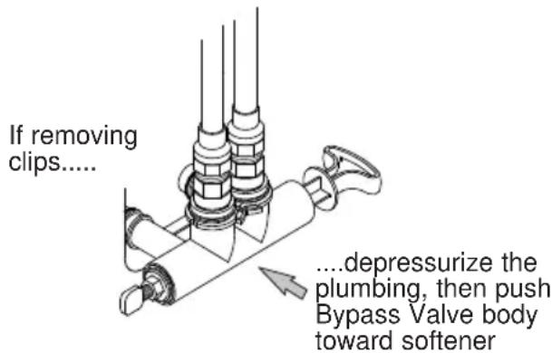
Check for leaks around clips at softener's inlet and outlet. If a leak occurs at a clip, depressurize the plumbing (turn off the water supply and open faucets) before removing clip. When removing clips at the softener's inlet or outlet, push the single bypass valve body toward the softener (See Figure 13). Improper removal may damage clips. Do not reinstall damaged clips.
ADD WATER AND SALT TO THE SALT STORAGE TANK
WARNING
EXCESSIVE WEIGHT HAZARD:
Use two or more people to move and lift salt bags. Failure to do so can result in back or other injuries.
- Using a container, add about three gallons of clean water into the salt storage tank.
- Add salt to the storage tank. Use nugget, pellet or coarse solar salts with less than 1% impurities.
PLUG IN THE WATER SOFTENER
- Plug the water softener into an electrical outlet that is not controlled by a switch.
- Replace the top cover.
- Replace the salt hole cover.
NOTE: The water heater is filled with hard water and, as hot water is used, it will refill with conditioned water. In a few days, the hot water will be fully conditioned. To have fully conditioned hot water immediately, wait until the initial recharge is over. Then, drain the water heater(following instructions for water heater) until water runs cold.
WARNING
Discard all unused
parts and packaging material after installation. Small parts remaining after the installation could be a choke hazard.
SANITIZE THE WATER SOFTENER / SANITIZE AFTER SERVICE
- Open salt hole cover, remove the brinewell cover and pour about 3 oz. (6 tablespoons) of household bleach into the softener brinewell. Replace the brinewell cover.
- Make sure the bypass valve(s) is in the "service"(open) position.
- Start a recharge (regeneration) as follows: Press the RECHARGE button and hold for three seconds, until "RECHARGE NOW" begins to flash in the display, starting a recharge. This recharge draws the sanitizing bleach or brine into and through the water softener. Any air remaining in the water softener is purged to the drain. During this time periodically check for leaks.
NOTE: As with all other water system applications, leaks may occur. Leaks may not be immediately apparent. Recheck 24 hours after first recharge cycle is complete. - After the recharge has completed, fully open a cold water faucet, downstream from the softener, and allow 50 gallons of water to pass through the system. This should take at least 20 minutes. Close the faucet.
Programming the Water Softener
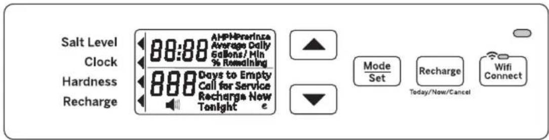
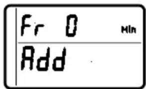
When the transformer is plugged into the electrical outlet, a model code and test number (example: y4.1 & H40) are shown in the display. Then, "12:00 PM" begins to flash. An arrow ◀ is displayed next to CLOCK on the face plate decal.
CONTROL OPERATION:
- CONTROL SETTINGS REQUIRED upon initial installation and after an extended power outage.
- Use the MODE/SET button to scroll arrow to desired control function set.
- After the mode is selected use the UP ▲ and DOWN ▼ buttons to change the settings of the control.
- Press the MODE/SET button to accept changes.
- A "beep" sounds while pressing buttons for control programming. One beep signals a change in the control display. Repeated beeps mean the control will not accept a change from the button you have pressed, and you should select another button.
SET TIME OF DAY
- Press MODE/SET button until the arrow points to CLOCK.
- Press the UP ▲ or DOWN ▼ buttons to set the present time. UP ▲ moves the display ahead; DOWN ▼ sets the time back. Be sure AM and PM is correct.
NOTE: Press buttons and quickly release to slowly advance the display one number at a time. Hold the buttons down for fast advance.
- When the correct time is shown in the display, press MODE/SET to accept.
SET WATER HARDNESS NUMBER
- Press the MODE/SET button until the arrow ◀ points to HARDNESS. A flashing 25 will appear in the display.
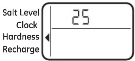
- Press the UP ▲ or DOWN ▼ buttons to set your water hardness number.
NOTE: If your water supply contains iron, compensate for it by adding to the water hardness number. For example, assume your water is 20 gpg hard and contains 2 ppm iron. Add 5 to the hardness number for each 1 ppm or iron. In this example, you would use 30 for your hardness number.
$$ \begin{array}{c} 2 0 \text { gpg hardness } \ 2 \text { ppm iron x 5 = } 1 0 \underline {{+ 1 0}} \ (\text { times }) \quad 3 0 \text { HARDNESS NUMBER } \end{array} $$
- When the display shows your water hardness (in grains per gallon), press MODE/SET to accept.
You can get the grains per gallon (gpg) hardness of your water supply from a water analysis laboratory. If you are on a municipal supply, call your local water department. Or call Legend Technical Services, an independent laboratory, to request a water hardness test kit at 1.800.949.8220, Option 4. If your report shows hardness in parts per million (ppm) or milligrams per liter (mg/l), simply divide by 17.1 to get the equivalent number of grains per gallon.
SET RECHARGE (STARTING) TIME
- Press the MODE/SET button until the arrow ◀ points to RECHARGE.
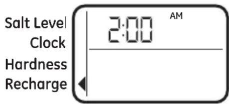
NOTE: A flashing 2:00 AM (factory default) should show in the display. This is a good time for recharge to start (takes about 2 hours) in most households because water is not in use. HARD WATER is bypassed to house faucets during recharge.
If no change is needed, go to step 3. To Change the recharge starting time, follow step 2.
-
Press UP▲ or DOWN ▼ button to set the desired recharge start time. Be sure to observe the AM or PM as you did when setting the time of day.
-
Press the MODE/SET button to accept.
Programming the Water Softener
SET SALT LEVEL
- Press the MODE/SET button until the arrow points to SALT LEVEL.
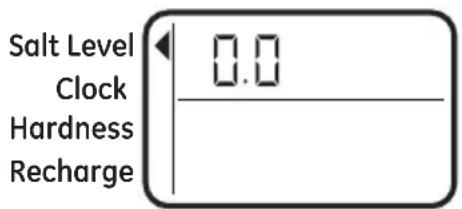
- Determine level of salt in brine tank using the numbered scale on side of brine well, inside brine tank (see Figure 14).
- Press UP▲ or DOWN ▼ button to set the SALT LEVEL to correspond to level on the numbered scale in brine tank.
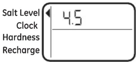
NOTE: Each press of a button changes the level by increments of 0.5 up to 8.0. Lowering the salt level below zero turns the SALT LEVEL indicator OFF.
- Press the MODE/SET button to accept. The display shows the present time of day and DAYS TO EMPTY.
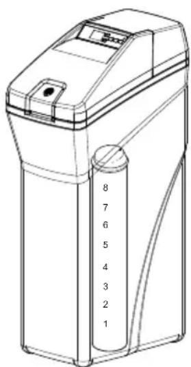
Figure 14
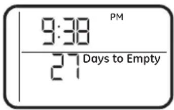
DAYS TO EMPTY
The words DAYS TO EMPTY and a number are shown in the lower half of the display. This information is shown in the normal run display. This is to inform the user of the number of days before the salt level in the brine tank reaches Level 0. There will be salt left in the salt tank, but it may not be sufficient to fully recharge the system. Salt should be added at this time to avoid hard water. The value is updated daily and whenever the SALT LEVEL value is changed.
NOTE: For the first several weeks of operation, the DAYS TO EMPTY may provide erratic operation. For example, the blue indicator light may flash, showing that more salt is required when the actual salt level in the tank is well above the Level 0. In some cases, the DAYS TO EMPTY may even increase over a several week period.
It takes a couple of months for the water softener to learn your water usage pattern. Once it does this, it will accurately determine actual salt usage pattern. During this first period, check salt level when blue indicator light flashes. If the salt level in the tank is at Level 1 or above, allow system to run. Be sure to reset your salt level indicator each time you add salt to the system.
START A RECHARGE
Press the RECHARGE button and hold for three seconds, until “RECHARGE NOW” begins to flash in the display, starting a recharge. This recharge draws the sanitizing bleach or brine into and through the water softener. Any air remaining in the water softener is purged to the drain. During this time periodically check for leaks.
NOTE: As with all other water system applications, leaks may occur. Leaks may not be immediately apparent. Recheck 24 hours after first recharge cycle is complete.
Appliance Communication: WiFi Connect
(For customers in the United States, its Territories, and Canada)
- WiFi communication requires WiFi connectivity and electrical power at the location of the softener. App connectivity will not function should either fail. (Check for both before the system is fully installed.)
- App requires smart phone with service to receive notifications.
- App provides alert, but requires user to respond to turn off water.
- The system is not able to detect all small leaks, and cannot shut off leaks between the system and shut off valve.
| Connected Appliance Information | |
| FCC: ZKJ-WCATA001 | Network: GE_XX00XX_XXXX |
| IC: 10229A-WCATA001 | Password: X00000XX |
| MAC ID: XX - XX - XX - XX - XX - XX | PT. NO. 229C6272G001-0 |
Sample Label
If your Water Softener is GE Appliances WiFi Connect capable, a WiFi communication card is built into the product allowing it to communicate with your smartphone for remote monitoring, control, and notifications.
To connect with your softener, please visit GEAppliances.com/connect to learn how to connect your appliance to your smartphone using the label located inside your softener and learn about the features of your app such as 1) Water usage monitoring 2) Low Salt Alert 3) Continuous water flow alerts 4) Remote water shutoff valve.
WiFi Connectivity: For assistance with your appliance network connectivity, please call GE Appliances at (800) 220-6899.
This device complies with Part 15 of the FCC Rules.
Operation is subject to the following two conditions:
- This device may not cause harmful interference, and
- This device must accept any interference received, including interference that may cause undesired operation. This equipment has been tested and found to comply with the limits for a Class B digital device, pursuant to Part 15 of the FCC Rules. These limits are designed to provide reasonable protection against harmful interference in a residential installation. This equipment generates uses and can radiate radio frequency energy and, if not installed and used in accordance with the instructions, may cause harmful interference to radio communications. However, there is no guarantee that interference will not occur in a particular installation. If this equipment does cause harmful interference to radio or television reception, which can be determined by turning the equipment off and on, the user is encouraged to try to correct the interference by one or more of the following measures:
- Reorient or relocate the receiving antenna.
- Increase the separation between the equipment and receiver
- Connect the equipment into an outlet on a circuit different from that to which the receiver is connected.
- Consult the dealer or an experienced radio/television technician for help.
Labelling: Changes or modifications to this unit not expressly approved by the manufacturer could void the user's authority to operate the equipment.
Programming the Water Softener
OPTIONAL CONTROL SETTINGS
The controller display has several options and features.
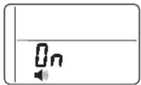
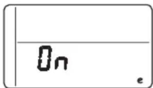
LOW SALT ALARM
The LOW SALT ALARM, when enabled, will sound the beeper when the DAYS TO EMPTY value is 15 days or less. To change this setting, press and hold the MODE/SET button for 3 seconds or hear a beep. ON (factory default) or OFF will flash in the display. Press the UP ▲ or DOWN ▼ buttons to toggle this feature ON or OFF. Press the MODE/SET button to accept, and the display will move to the SALT EFFICIENCY screen.
natural_image
Simple diagram with a speaker icon and a vertical line, no text or symbols presentSALT EFFICIENCY
When the SALT EFFICIENCY feature is
ON, the unit will operate at a salt efficiency of 4000 grains of hardness removed per pound of salt. This mode of operation is the most efficient setting for salt usage, because the system will tend to recharge more often with less salt usage. Turning the feature OFF will tend to lengthen the time between recharge cycles, which will provide the most efficient usage of water, but may use more salt. The degree of difference between these two cycles is highly dependent on the water usage and hardness at particular installation.
NOTE: California Regulations require this feature to be ON for installations in California.
To change the setting, press the UP ▲ or DOWN ▼ buttons to toggle this feature ON or OFF. Press the MODE/SET button to accept, and the display will move to the PRERINSE ON/OFF screen.
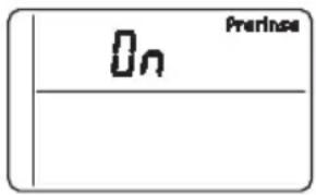
PRERINSE
If your water contains sediment, the prerinse feature will remove sediment from the resin bed prior to regeneration. Press the UP ▲ or DOWN ▼ buttons to turn prerinse ON or OFF.
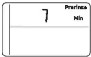
Press the MODE/SET button to accept, and the display will move to SET PRERINSE TIME screen. In this screen, you can adjust the duration of the prerinse, in minutes, by pressing the UP ▲ or DOWN ▼ buttons. Press the MODE/SET button to accept, and the display will move to the ADD BACKWASH TIME screen.
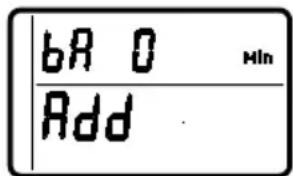
BACKWASH AND FAST RINSE
If you experience salty tasting water after regeneration, you may need to increase the backwash and fast rinse times. The cycle times during regenerations are determined by the softener's electronic controller. However, you may Increase the backwash and fast rinse times. You may add up to 10 minutes.
For Backwash, you can add up to 10 minutes in 1 minute increments, by pressing the UP ▲ button, or subtract time by pressing the DOWN ▼ button.
For Fast Rinse, press MODE/SET and the display moves to the ADD FAST RINSE TIME screen. You can add up to 10 minutes in 1 minute increments, by pressing the UP ▲ button, or subtract time by pressing the DOWN ▼ button. Press the MODE/SET button to accept, and the display will move to the Run Display screen.
Programming the Water Softener
FEATURE: OTHER DATA DISPLAY
These models have an option to have the run display indicate different information. The information displayed on the top half of the display can be changed to one of the following by pressing UP ▲ or DOWN ▼ buttons:
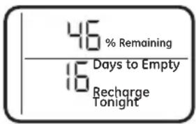
• CAPACITY REMAINING
- This is the percentage of water softening capacity remaining. Immediately after a regeneration, 100% shows. As water is used, the percentage will decrease until the next regeneration. During regenerations, the percentage increments upward.
When present time is displayed, press the DOWN ▼ button; % Remaining will appear in the display. The value shown is between 0 and 100 percent. This value is based on current operating capacity. Pressing the UP ▲ button will return the screen to the previous display.
• AVERAGE DAILY
GALLONS – The figure displayed is the average gallons of water used by the household each day over the past seven-day period.
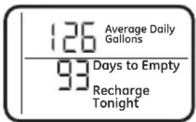
Press the DOWN ▼ button again to display the Average Daily Gallons. Average Daily Gallons will appear in the display. This value is updated every night at midnight. Pressing the UP ▲ button will return the screen to the previous display.
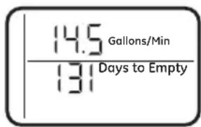
- FLOW RATE, GPM
- When using soft water, this display shows the flow rate passing through the softener (in gallons per minute). Zero shows if water is not passing through the softener.
Press the DOWN ▼ button again to display the flow rate. Gallons/Min will appear in the display. This value is updated every 12 second.
Pressing the UP ▲ button will return the screen to the previous display. Pressing the DOWN ▼ button will return the screen to the present time display.
RESETTING TO FACTORY DEFAULT
To reset the electronic controller to its factory default for all settings (time, hardness, etc.):
- Press the MODE/SET button and hold until the display changes twice to show the flashing mode code.
- Press the UP ▲ button to display a flashing "SoS".
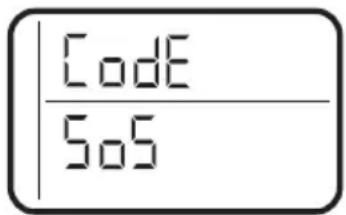
-
Press the MODE/SET button and the electronic controller will restart.
-
Set the present time, hardness, etc, as described in the Programming the Water Softener section
Programming the Water Softener
POWER OUTAGE MEMORY
If electrical power to the water softener is lost, “memory” built into the timer circuitry will keep all settings for up to 24 hours. While the power is out, the display is blank and the water softener will not regenerate. When electrical power is restored, the following will occur:
Reset the present time only if the display is flashing. The HARDNESS and RECHARGE TIME never require resetting unless a change is desired. Even if the clock is incorrect after a long power outage, the softener operates as it should to keep your water soft. However, regenerations may occur at the wrong time of day until you reset the clock to the correct time of day.
NOTE: If the water softener was regenerating when power was lost, it will now finish the cycle.
BLUE INDICATOR LIGHT
Steady blue light indicates that the unit is working correctly. The light flashes when the unit needs attention from the user.
- Light will also flash when power to the unit has been interrupted. Check the PRESENT TIME setting.
- Light flashes and DAYS TO EMPTY flashes - check salt level and add salt as required.
- Light flashes and Err is in the display - electrical problem with system.
LOW SALT SIGNAL
When the DAYS TO EMPTY drops to 15, the blue indicator light and DAYS TO EMPTY in the display will flash every second and the alarm will beep every 30 seconds (from 8:00 AM to 8:00 PM), to notify the user that the unit is running low on salt. As soon as any button is pressed, the alarm will stop beeping. The blue indicator light and DAYS TO EMPTY will continue to flash. Once salt is added to the brine tank and the SALT LEVEL is reset, the DAYS TO EMPTY will be reset.
ERROR SIGNALS
If there is an error code detected, the blue indicator light will flash 4 times every second, the display will flash Err and the alarm will beep
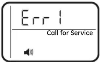
every 30 seconds (from 8:00 AM to 8:00 PM) to signal that the softener requires service. The alarm can be turned off by pressing any button, but the blue indicator light and display will continue to flash.
Disconnect the transformer from the wall outlet momentarily, and plug it back in. The normal display will appear. The motor may run for several minutes, as the unit resets. If the problem is not corrected, the error code will reappear in 8 minutes. If Err 6, 7, or 8 appears, it can be cleared by pressing recharge for 5 seconds. See the Before you Call for Service section to assist in troubleshooting the water softener.
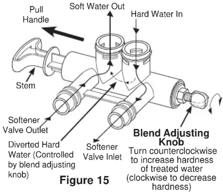
ADJUSTING YOUR WATER HARDNESS
The blend adjusting knob (Figure 15) gives the ability to finely adjust hardness of the treated water leaving the water softener. If slightly harder water is desired than is normally delivered by the water softener, the blend adjusting knob can divert a small stream of hard water and blend it with the soft water entering the home. The amount of water diverted is controlled by turning a blend adjusting knob on the end cap of the valve stem.
NOTE: To get full performance from your water softener leave blending valve in the factory closed position.
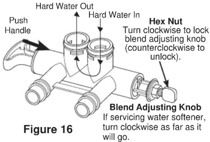
To make adjustments to water hardness:
- Hold bypass handle to keep the valve stem from rotating (see Figure 16). Loosen hex nut on blend adjustment knob by turning the hex nut counterclockwise (see Figure 16).
-
TO INCREASE HARDNESS: With the bypass in the service position (see Figure 16) hold the handle to keep the valve stem from rotating and turn the blend adjusting knob counterclockwise up to 2 turns from the closed position. It is recommended that adjustments be made in quarter turn increments over several weeks until the desired hardness is achieved. NOTE: Once an adjustment is made to the blend valve knob the change in water hardness at the homes faucets or shower heads may take several days to be noticed. This delay is due to the large amounts of already conditioned water in the pipes and water heater that must be exchanged before a change in hardness can be noticed. Have the water tested to determine the actual water hardness.
-
TO DECREASE HARDNESS: With the bypass in the service position (see Figure 16) hold the handle to keep the valve stem from rotating and turn the blend adjusting knob clockwise. When the knob will not turn anymore, hard water is no longer being blended into the soft water.
-
Once the desired hardness is achieved tighten the hex nut (see Figure 16) clockwise until it comes in contact with the bypass stem.
NOTE: To meet the water softener performance specifications and reduction of barium and radium claims the adjustable hardness must be kept in the "OFF" position. The off position is achieved when the blend adjusting knob is fully rotated clockwise until it stops.
SERVICE POSITION
(Normal Softener Operation)
BYPASS POSITION
CAUTION
If the water
softener is to be serviced or disconnected from the bypass valve, the blend adjusting knob must be turned all the way clockwise to close the diversion path and prevent water leaking from the softener valve inlet of the bypass.
CHECKING THE SALT STORAGE LEVEL and REFILL
Brine (salt dissolved in water) is needed for each and every recharge. The water for making brine is metered into the salt storage area by the water softening system valve and control.
However, you must keep the tank supplied with salt.
ADDING SALT
Lift the salt hole cover and check the salt storage level frequently. If the water softener uses all the salt before you refill it, you will experience hard water. Until you have established a refilling routine, check the salt every two or three weeks. Always add if less than 1/4 full. Be sure the brinewell cover is on.
NOTE: if using potassium chloride (KCl), do not fill above level 4 on the brinewell decal.
NOTE: In humid areas, it is best to keep the salt storage level lower, and to refill more often to avoid salt “bridging”.
Recommended Salt: Nugget, pellet or coarse solar salts with less than 1% impurities.
Salt Not Recommended: Rock salt, high in impurities, block, granulated table, ice melting, ice cream making salts, etc.

Water softening
salt with iron removing additives: Some salts may have an additive to help the water softening system handle iron in the water supply. Although this additive may help to keep the water softening system resin clean, it may also release corrosive fumes that weaken and shorten the life of some water softening system parts.
CLEANING IRON OUT OF THE WATER SOFTENING SYSTEM
Your water softening system takes hardness minerals (calcium and magnesium) out of the water. Also, it can control some (see the Specification Guidelines section) “clear water” iron. With clear water iron, water from a faucet is clear when first put into a glass. After 15 to 30 minutes, the water begins to cloud or turn rust colored. A water softening system will not remove any iron that makes the water cloudy or rusty as it comes from the faucet (called red water iron). To take red water iron out of water, or over the maximum of clear water iron, an iron filter or other equipment is needed.
GE Appliances recommends using Super Iron Out ^® to clean your resin bed if your iron content is high. Use Super Iron Out ^® with every 40lb. bag of salt as preventative maintenance against rust build up. Clean the bed at least every six months, or more often if iron appears in the soft water between cleanings.
IMPORTANT: It is important to mix the resin bed cleaner with water (following the manufacturer's instructions), pour it into the brinewell (see Figure 9) and recharge the softener immediately. Do not pour the resin bed cleaner in with the salt, as it will not be as effective in cleaning the resin, and can cause damage to the softener if it is left in the brine tank for an extended period due to the corrosive gases that are formed.
Routine Maintenance
CLEANING THE NOZZLE AND VENTURI ASSEMBLY
A clean nozzle and venturi is needed for the water softening system to work properly.
This small unit makes the suction to move brine from the salt storage area to the resin tank during recharge. If it becomes plugged with sand, dirt, etc., the water softening system will not work and you will get hard water.
To get to the nozzle and venturi, remove the water softening system top cover. Be sure the water softening system is in service cycle (no water pressure at nozzle and venturi). Then, while holding the nozzle and venturi housing with one hand, remove the cap. Lift out the screen support and screen, then the nozzle and venturi. Wash and rinse the parts in warm water until clean. If needed, use a small brush to remove iron or dirt. Also check and clean the gasket.
NOTE: Some models have a small flow plug located in the nozzle and venturi, and/or a small cone shaped screen in the housing. Be sure to check and clean these parts, if your model is so equipped.
Carefully replace all parts in the correct order. Lightly lubricate the o-ring seal with clean silicone grease or petroleum jelly and place in position. Install and tighten the cap, by hand only. Do not overtighten the cap.
BREAKING A SALT BRIDGE
Sometimes, a hard crust or salt bridge forms in the salt storage area. It is usually caused by high humidity or the wrong kind of salt.
When the salt bridges, an empty space forms between the water and salt. Then salt will not dissolve in the water to make brine.
If the brine tank is full of salt, it is hard to tell if you have a salt bridge. Salt is loose on top, but the bridge is under it. The following is the best way to check for a salt bridge.
Salt should be loose all the way to the bottom of the tank. Take a broom handle or like tool, and carefully push it down into the salt, working it up and down. If the tool strikes a hard object (be sure it's not the bottom or sides of the tank), it's most likely a salt bridge. Carefully break the bridge with the tool. Do not pound on the walls of the tank. To help dissolve the salt bridge pour one gallon of warm water (not hot) into the tank. If the wrong kind of salt made the bridge, take it out. Then fill the tank with nugget or pellet salt only. In humid areas, it is best to fill with less salt, more often to prevent a salt bridge from forming.
Cap
O-ring seal
Screen support
Screen
*Flow plug
Nozzle and
Venturi
Gasket
*Flow plug
Screen
Ferrule Nut
IMPORTANT: Be sure small holes in the gasket are centered directly over the small holes in the nozzle and venturi housing.
* Install with numbered side up, concave side down.
Push tool into salt
bridge to break
1"-2"
Pencil
mark
Broom
handle
Salt
Salt bridge
Water level
Before you call for service
Troubleshooting Tips
Save time and money! Review the chart on this page first and you may not need to call for service.
NO SOFT WATER – Most Common Problems:
Check the following before calling for service:
- Not enough salt—should be at least 1/3 full.
- Bypass valve in "Bypass" position—handle should be in the "OUT" (service) position.
- Hardness setting too low. Check hardness setting and adjust. Verify hardness of supply water—from local water company, water test or call the GE Appliances Answer Center (800-952-5039 in US).
- Salt Bridge—salt solidifies above water level so that brine water is not in contact with salt. See the Breaking a Salt Bridge section.
| Problem Possible Cause What to do | ||
| No soft water Faucet or fixture where sample was taken not plumbed to soft water. NOTE: Be sure sample is from a faucet that does not mix soft and hard water. For example, a single lever kitchen faucet, if the cold side is plumbed to hard water. | · To conserve salt, the installer may have isolated some fixtures (outside faucets, toilets, etc.) from soft water. From the outlet of the water softening system, trace the water flow path in the house plumbing. If soft water is not directed to a faucet or fixture where wanted, consult a plumber. | |
| No salt in the brine tank or salt bridged | · Check for a salt bridge or, if the tank is empty, refill with recommended salt. Press (for 3 seconds) the RECHARGE button to start an immediate recharge and restore soft water supply. | |
| External power supply unplugged at wall outlet or power cable to softener not connected. Fuse blown or circuit breaker popped on circuit to electrical outlet. Electrical outlet on a circuit that can continuously be switched off | · Check for a loss of electrical power to the water softening system, due to any of these conditions and correct as needed. With the power supply restored, observe the faceplate time display and read Programming the Control section. NOTE: the electrical outlet for the softener should be live so it cannot be accidentally switched off. | |
| Manual bypass valve in bypass position | · Be sure the bypass valve stem is positioned properly, with the handle in the OUT position. | |
| Blending valve in open position | · Turn blending valve clockwise to closed position. | |
| Valve drain hose pinched, plugged, elevated too high or otherwise restricted | · Any restriction in the drain hose may prevent proper operation of the nozzle and venturi and reduce or prevent brine draw during recharge. | |
| Nozzle and venturi dirty, incorrectly assembled or damaged | · Refer to Cleaning the Nozzle and Venturi Assembly instructions. With water pressure to the water softening system off, take the nozzle assembly apart. Inspect, clean and replace as needed. Any foreign particle(s), scratches, nicks, etc. in the passages can prevent operation. Be sure holes in the gasket are centered over holes in the housing. | |
Before you call for service
| Problem Possible | Cause What to do | |
| Water hard sometimes | Using hot water while the water softening system is regenerating | · Avoid using hot water during water softening system recharge because the water heater will refill with hard water. See Automatic Hard Water Bypass During Recharge section. |
| Control HARDNESS number setting too low | · Press MODE/SET button until arrow points to HARDNESS. Be sure the number shown is the same as the actual grains per gallon hardness of your water supply. See Programming the Control section if a change in setting is needed. | |
| Grains of hardness in your water supply have increased | · Water hardness can change over time, especially in well water. To check, have the water tested by a water analysis laboratory or call your local water department. Adjust the Hardness number setting as needed. | |
| Water feels slippery after installation of water softener | Absence of hardness minerals | · This is normal. Hardness in water gives it the abrasive feel you may have been accustomed to. The slippery feel is the clean feel of soft water.· See the Adjusting your Water Hardness section. |
| Water Softener not using any salt | Water softening system is a “demand” unit | · Does not use much salt to regenerate - very efficient. |
| Possible salt bridge | · See the Breaking a Salt Bridge section. | |
| Possible plugged nozzle and venturi | · See the Cleaning the Nozzle and Venturi Assembly section. | |
| Water is blue color after water softener was installed | Acidic water in copper plumbing | · Have the water tested at once. |
| Water softener not regenerating | Meter turbine stuck · See the Manually Initiated Electronics Diagnostics section for troubleshooting procedures.· Call for service. | |
| Sensor wire not plugged into the control | · See the Manually Initiated Electronics Diagnostics section for troubleshooting procedures.· Call for service. | |
| No power to unit · Check the circuit breaker or fuses. | ||
| Mechanical defect · Call for service. | ||
| Cloudiness on glassware (automatic dishwashers) | Combination of soft water and too much detergent | · This is called etching and is permanent. To prevent this from happening, use less detergent if you have soft water. Wash glassware in the shortest cycle that will get them clean. |
Before you call for service
Problem Possible Cause What to do
| Excessive/high level of water in brine tank | Valve drain hose pinched, plugged, elevated too high or otherwise restricted | A restriction in this drain hose may prevent proper operation of the nozzle and venturi and reduce or prevent brine draw during recharge. |
| Drain lines connected together • Separate drain lines. | ||
| Nozzle and venturi dirty, incorrectly assembled or damaged. | Refer to Cleaning the Nozzle and Venturi Assembly instructions. With water pressure to the water softening system off, take the nozzle assembly apart. Inspect, clean and replace as needed. Any foreign particle(s), scratches, nicks, etc. in the passages can prevent operation. Be sure holes in the gasket are centered over holes in the housing | |
| Salty tasting or brown/yellow colored water after installation | Unit not sanitized • Complete Sanitization Procedures. | |
| Low water pressure Check pressure: | ||
| Restricted drain hose • Clean and reconnect hose. | ||
| Brown/yellow colored water | Unit was idle for a period of time • Complete the Sanitization Procedures. | |
| Resin beads showing up in drinking water | Cracked distributor or unit plumbed backwards | Check softener “IN & OUT” plumbing is correct. Call for service. |
| Sounds you might hear | Running water from the unit into a drain during recharge | This is normal. |
| Water has air bubbles and is cloudy | Air in system after installation • Will go away after it runs for a while. | |
| Blue light flashing when power applied to the system | Control needs to be programmed (a power outage may have occurred) | See the Programming the Control section. |
| If “DAYS TO EMPTY” is flashing | Low salt level, less than 15 days • Fill with salt. Reset salt level. | |
Before you call for service
| Problem Possible Cause What to do | ||
| Error Codes 1,3,4,5 on Control | Wiring may have worked loose in the control | · Unplug external power supply.· Remove control cover, release clips on side.· Check for loose/incorrect wiring connections to electronic board or switch. Reconnect as required.· Reassemble control cover.· Plug in Transformer.· Wait 8 minutes for Error Code to reappear.· If error Code reappears, call for service. |
| Error Codes 6,7,8 on Control | Issue with Water Shutoff valve | · Unplug external power supply.· Replace the water Shutoff valve.· Check for loose/incorrect wiring connections to electronic board. Reconnect as required.· Reassemble control cover.· Plug in Transformer.- When the Error 6,7 or 8 is displayed, press and hold the Recharge button for 5 seconds.· Wait 2 minutes for Error Code to reappear.· If error Code reappears, call for service. |
| If “Err” in display Electrical problem with system | · Call for service. | |
Advanced troubleshooting for service
AUTOMATIC ELECTRONIC
DIAGNOSTICS
This water softener has a self-diagnostic function for the electrical system (except into power and/or water meter).
The water softener monitors electronic components and
circuits for correct operation. If a malfunction occurs, an error code appears in the display.
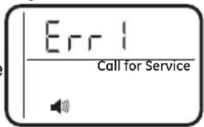
Figure 17
While an error code appears in the display, all buttons are inoperable except the MODE/SET button. MODE/SET remains operational so the service person can perform the Manual Advanced Diagnostics, see below, to further isolate the problem.
Procedure for removing error code from display:
- Unplug transformer from electrical outlet.
- Correct problem.
- Plug in transformer.
- Wait 8 minutes. The error code will return if the problem was not corrected.
MANUAL INITIATED ELECTRONIC DIAGNOSTICS
Use the following procedures to advance the water softener through the regeneration cycles to check operation.
Lift off the Salt Hole Cover, remove the top cover by unlocking the tabs in the back and rocking forward, to observe cam and switch operation during valve rotation.
- Press and hold MODE/SET for 3 seconds until the Set low salt alarm display appears, next press the MODE/SET button two addition times until "000" shows in the display, then release, see Figure 18.
- The 3 digits indicated water meter operation as follows: If you don't get a reading on the display, with faucet open, pull the sensor from the valve outlet port. Pass a small magnet back and forth in front of the sensor. You should get a reading in the display. If you get a reading, shut off water supply, unhook the in and out plumbing and check the turbine for binding.
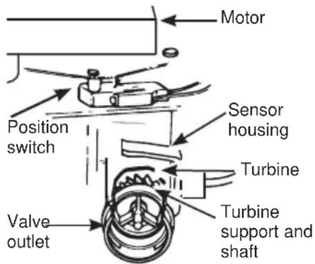
MANUAL INITIATED ELECTRONIC DIAGNOSTICS
- Symbols in the display indicate POSITION switch operation, (see Figure 18).
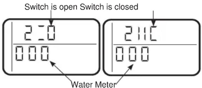
Figure 18
- Use RECHARGE button to manually advance the valve into each cycle and check correct switch operation. NOTE: Be sure water is in contact with salt, and not separated by a salt bridge (see Breaking a Salt Bridge section).
- While in this diagnostic screen, the following information is available and may be beneficial for various reasons. This information is retained by the computer from the first time electrical power is applied to the electronic controller.
a. Press the ▲UP button to display the number of days this electronic control has had electrical power applied.
b. Press the ▼DOWN button to display the number of regenerations initiated by the electronic control since the code number was entered.
- Press and hold the MODE/SET button until the mode code (H40 for GXSHC40N) shows in the display (see Figure 19). This code identifies the softener mode. If an incorrect model code is displayed, the softener will operate on incorrect configurations data.
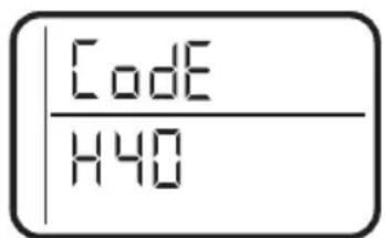
Figure 19
- To change the code number, press the ▲ UP or ▼ DOWN button until the correct code shows.
- To return to the present time display, press the MODE/SET button.
- Press the MODE/SET button to return to the present time display. If the code was changed, make all the timer setting.
NOTE: If the control is left in a diagnostic display or a flashing display when setting times or hardness, present time automatically returns if a button is not pressed within four minutes.
Advanced troubleshooting for service
Service: Manually Advance Recharge Check
NOTE: The control display must show a steady time (not flashing).
-
Press the RECHARGE button and hold in for three seconds. RECHARGE begins to flash as the water softening system enters the fill cycle of recharge. Remove the brinewell cover and, using a flashlight, observe fill water entering the brine tank. If water does not enter the tank, look for an obstructed nozzle, venturi, fill flow plug or brine tubing. See Care and Cleaning of the Water Softener System section.
-
After observing fill, press the RECHARGE button to move the water softening system into brining. A slow flow of water to the drain will begin. Verify brine draw from the brine tank by shining a flashlight into the brinewell and observing a noticeable drop in the liquid level over an extended period of time (is to 20 minutes).
NOTE: Be sure a salt bridge is not preventing water from contacting salt. See Care and cleaning of the water softening system section. If the water softening system does not draw brine, check:
nozzle and/or venturi dirty or defective.
■ defective nozzle and venturi seal.
- nozzle and venturi not seated properly on gasket.
other inner valve defect (rotor seal, rotor and disc, wave washer, etc.).
■ restricted drain (check drain fitting and hose).
NOTE: If water system pressure is low, an elevated drain hose may cause back pressure, stopping brine draw.
-
Again, press the RECHARGE button to move the water softening system into backwash. Look for a fast flow of water from the drain hose. A slow flow indicates a plugged top distributor, backwash flow plug or drain hose.
-
Press the RECHARGE button to move the water softening system into fast rinse. Again look for a fast drain flow. Allow the water softening system to rinse for a few minutes to flush out any brine that may remain in the resin tank from the brining cycle test.
- To return the water softening system to service, press the RECHARGE button.
Position Markers (valve in service)
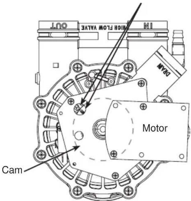
Figure 20
Valve Positions:
| Position Function | |
| S Service | |
| F Fill | |
| BR Brine Fill | |
| BW Back Wash | |
| R Rinse | |
Exploded View/Parts List
scatter
| Point | X | Y | |---|---|---| | 1 | 4 | 11 | | 2 | 4 | 16 | | 3 | 7 | 56 | | 4 | 8 | 8 | | 5 | 9 | 10 | | 6 | 6 | 29 | | 7 | 7 | 56 | | 8 | 8 | 24 | | 9 | 9 | 26 | | 10 | 10 | 24 | | 11 | 11 | 11 | | 12 | 12 | 12 | | 13 | 13 | 13 | | 14 | 14 | 146 | | 15 | 15 | 5 | | 16 | 16 | 23 | | 17 | 17 | 20 | | 18 | 18 | 22 | | 19 | 19 | 23 | | 20 | 20 | 8 | | 21 | 21 | 7 | | 22 | 22 | 6 | | 23 | 23 | 5 | The chart displays a single column of numbers (e.g., '4', '40', '41') representing the positions of the data points on the x-axis. There are no labels or additional data series in this image.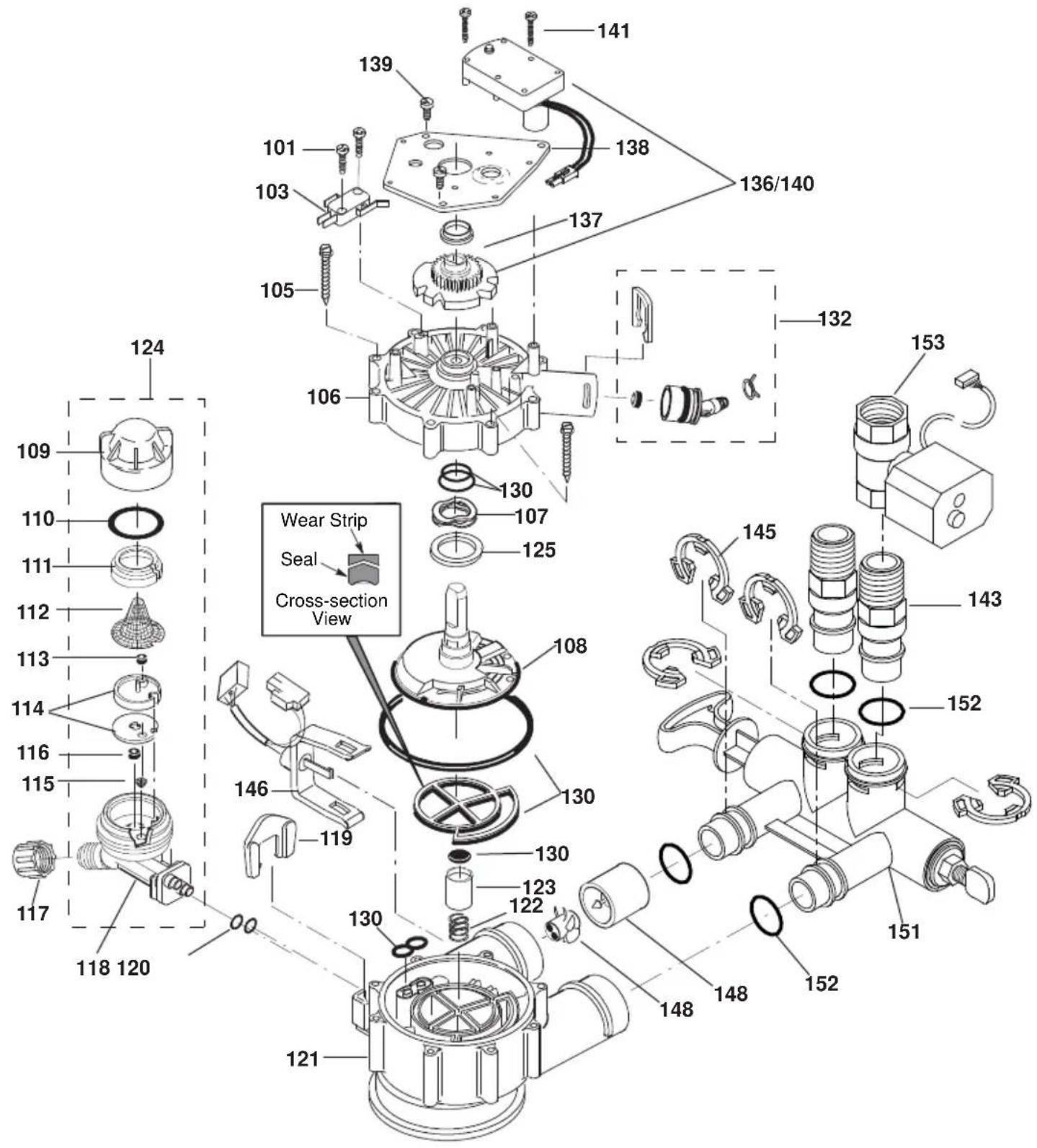
GXSHC40N
REF. NO. GEA PART NO. PART DESCRIPTION (01)
| 0002 | WS31X10051 | BACK COVER, ELECTRONICS | 1 | ||
| 0003 | WS35X10001 | O-RING | SEAL | KIT | 1 |
| 0004 | WS35X21986 | DECAL, | FACEPLATE | 1 | |
| 0005 | WS07X10004 HOSE, DRAIN, 20 FT. 1 | ||||
| 0006 | WS31X10044 | FILTER | SCREEN | 1 | |
| 0007 | WS14X10002 | DISTRIBUTOR, | TOP | 1 | |
| 0008 | WS14X10005 | DISTRIBUTOR, | BOTTOM | 1 | |
| 0009 | WS01X10002 RESIN, 1-CU. FT. 1 | ||||
| 0010 | WS32X10011 TANK, RESIN 9 X 40 | ||||
| 0011 | WS31X10052 | COVER, | TOP | 1 | |
| 0012 | WS34X10021 | FACEPLATE | 1 | ||
| 0013 | WS35X21984 MAIN CONTROL BOARD KIT | 1 | |||
| 0016 | WS26X22083 EXTERNAL POWER SUPPLY WITH POWER CORD | 1 | |||
| 0017 | WS31X10053 COVER, SALT HOLE, WITH LABELS | 1 | |||
| 0019 | WS33X21987 | RIM | 1 | ||
| 0020 | WS33X10024 | COVER, | BRINEWELL | 1 | |
| 0022 | WS34X10025 | BRINEWELL | 1 | ||
| 0023 | WS02X10088 SCREW KIT, BRINE TANK | 1 | |||
| 0024 | WS32X10032 | TANK, | BRINE | ||
| 0026 | WS22X10063 | OVERFLOW ADAPTER KIT | 1 | ||
| 0029 | WS15X24201 BRINE VALVE ASM. | 1 | |||
| 0040 | WS35X21981 | WIFI | MODULE | KIT | |
| 0041 | WS01X21982 | HOLDER, | WIFI | MODULE | |
| 0042 | WS21X21983 | CABLE | ASM., | WIFI | MODULE |
| 0056 | WS28X10078 TANK NECK CLAMP KIT | 1 | |||
| 0101 | WS02X10023 | SCREW. # 4 - 24 X 3/4" | 2 | ||
| 0103 | WS21X10003 | SWITCH | 1 | ||
| 0105 | WS02X10024 | SCREW. # 10 - 2 5/8" | 8 | ||
| 0106 | WS31X10013 | COVER, | VALVE | ||
| 0107 | WS03X10034 | WASHER WAVE | 1 | ||
| 0108 | WS26X10010 ROTOR & DISC ASM. 1 | ||||
| 0109 | WS19X10010 CAP | 1 | |||
| 0110 | WS03X10011 | SEAL, | O-RING | 1.125 X 1.37 | |
GXSHC40N
REF. NO. GE PART NO. PART DESCRIPTION (01)
| 0111 | WS19X10005 | SUPPORT | SCREEN | 1 | ||
| 0112 | WS03X10013 | SCREEN | 1 | |||
| 0113 | WS22X10036 FLOW PLUG, .15 GPM 1 | |||||
| 0114 | WS08X10008 | GASKET, | NOZZLE/VENTURI | 1 | ||
| 0115 | WS03X10073 | CONE | SCREEN | 1 | ||
| 0116 | WS22X10021 PLUG, FILL FLOW .30 GPM 1 | |||||
| 0117 | WS03X10017 | NUT | FERRULE | 1 | ||
| 0118 | WS15X10034 | NOZZLE/VENTURI | BODY | 1 | ||
| 0119 | WS03X10018 | RETAINER | 1 | |||
| :6 ; | 6(/ 2 5,1* | ∃ ; | ∃ | |||
| 0121 | WS15X10025 | BODY, | VALVE | 1 | ||
| 0122 | WS03X10020 | SPRING | 1 | |||
| 0123 | WS22X10029 PLUG, DRAIN SEAL | 1 | ||||
| 0124 | WS15X10046 | NOZZLE/VENTURI | ASM. | 1 | ||
| 0125 | WS03X10043 | WAVE | SPRING | BEARING | ||
| 0130 | WS35X10020 | SEAL | KIT | 1 | ||
| 0132 | WS22X10065 | DRAIN HOSE ADAPTER KIT | 1 | |||
| 0136/0140 | WS26X21821 MOTOR, CAM & GEAR KIT, 1" | 1 | ||||
| 0137 | WS26X10009 | BEARING | 1 | |||
| 0138 | WS26X10023 | PLATE, | MOTOR | 1 | ||
| :6 ; | 6&5( : ; ∃ | |||||
| :6 ; | 6&5( : ; ∃ | |||||
| :6 ; | 37(5±137 7+5('± ∃ 9$/9( | |||||
| 0145 | WS60X10008 | CLIP | 4 | |||
| 0146 | WS28X10018 HARNESS WIRE, SENSOR ASSY | 1 | ||||
| 0148 | WS26X10030 TURBINE & SUPPORT ASSEMBLY* | 1 | ||||
| 0151 | WS15X10078 | BYPASS | ASM. | 1 | ||
| 0152 | WS03X10072 | SEAL, | O-RING | 4 | ||
| 0153 | WS15X21985 WATER SHUTOFF VALVE | 1 | ||||
| 0998 | WS35X10065 | INSTALLATION | KIT | 1 | ||
* Includes 2 each of REF. NO. 145 (CLIP) & REF. NO. 152 (O-RING)
FOR IOWA USE ONLY
All sales in Iowa require the following signature before consummation of sale. These signatures must be retained by seller/renter for 2 years minimum.
Buyer/Renter Date
Seller Date
Seller's Address
Seller's Phone No. ____
Model GXSHC40N
Notes
Water Softening System Limited Warranty (For Customers in the U.S.)
All warranty service provided by our Factory Service Centers or an authorized technician. For service, call toll free 1-800-952-5039. Please have serial number and model number available when calling for service.
| For The Period Of: | We Will Replace: |
| One YearFrom the date of the original purchase | Any part of the Water Softening System which fails due to defect in materials or workmanship. During this limited one-year warranty, GE Appliances will also provide, free of charge, all labor and related service to replace the defective part. |
| Three YearsFrom the date of the original purchase | The electronic monitor, if it fails due to a defect in materials or workmanship. During this three-year limited warranty, you will be responsible for any labor or related service cost. |
| Ten YearsFrom the date of the original purchase | A replacement resin tank, if it fails due to defect in materials or workmanship. During this ten-year limited warranty, you will be responsible for any labor or related service costs. |
What Is Not Covered:
■ Service trips to your home to teach you how to use the product.
■ Improper installation, delivery or maintenance.
■ Failure of the product if it is abused, misused, altered, used commercially or used for other than the intended purpose.
■ Use of this product where water is microbiologically unsafe or of unknown quality, without adequate disinfection before or after the system.
■ Replacement of house fuses or resetting of circuit breakers.
■ Damage to the product caused by accident, fire, floods or acts of God.
■ Incidental or consequential damage caused by possible defects with this appliance, its installation or repair.
■ Product not accessible to provide required service.
If this appliance is used for other than private family use, the parts, electronic monitor, and resin tank warranty applies for only 90 days from the date of purchase.
EXCLUSION OF IMPLIED WARRANTIES—Your sole and exclusive remedy is product repair as provided in this Limited Warranty. Any implied warranties, including the implied warranties of merchantability or fitness for a particular purpose, are limited to one year or the shortest period allowed by law.
This limited warranty is extended to the original purchaser for products purchased for home use within the USA. If the product is located in an area where service by a GE Appliances Authorized Servicer is not available, you may be responsible for a trip charge or you may be required to bring the product to an Authorized GE Appliances Service location for service. In Alaska, the limited warranty excludes the cost of shipping or service calls to your home.
Some states do not allow the exclusion or limitation of incidental or consequential damages. This limited warranty gives you specific legal rights, and you may also have other rights which vary from state to state. To know what your legal rights are, consult your local or state consumer affairs office or your state's Attorney General.
Warrantor: GE Appliances, a Haier company, Louisville, KY 40225
Water Softening System Limited Warranty (For Customers in the Canada)
All warranty service provided by our Factory Service Centers or an authorized technician. For service, call toll free 1-866-777-7627. Please have serial number and model number available when calling for service.
| For The Period Of: We Will Replace: | |
| One YearFrom the date of the original purchase | Any part of the Water Softening System which fails due to defect in materials or workmanship. During this limited one-year warranty, GE Appliances will also provide, free of charge, all labor and related service to replace the defective part. |
| Three YearsFrom the date of the original purchase | The electronic monitor, if it fails due to a defect in materials or workmanship. During this three-year limited warranty, you will be responsible for any labor or related service cost. |
| Ten YearsFrom the date of the original purchase | A replacement resin tank, if it fails fails due to defect in materials or workmanship. During this ten-year limited warranty, you will be responsible for any labor or related service costs. |
What Is Not Covered:
■ Service trips to your home to teach you how to use the product.
- Improper installation, delivery or maintenance.
- Failure of the product if it is abused, misused, altered, used commercially or used for other than the intended purpose.
■ Use of this product where water is microbiologically unsafe or of unknown quality, without adequate disinfection before or after the system.
■ Replacement of house fuses or resetting of circuit breakers.
■ Damage to the product caused by accident, fire, floods or acts of God.
■ Incidental or consequential damage caused by possible defects with this appliance, its installation or repair.
■ Product not accessible to provide required service.
If this appliance is used for other than private family use, the parts, electronic monitor, and resin tank warranty applies for only 90 days from the date of purchase.
EXCLUSION OF IMPLIED WARRANTIES—Your sole and exclusive remedy is product repair as provided in this Limited Warranty. Any implied warranties, including the implied warranties of merchantability or fitness for a particular purpose, are limited to one year or the shortest period allowed by law.
This limited warranty is extended to the original purchaser for products purchased for home use within Canada. In-home warranty service will be provided in areas where it is available and deemed reasonable by Mabe to provide.
WARRANTOR IS NOT RESPONSIBLE FOR CONSE QUEN TIAL DAMAGES.
Warrantor: MABE CANADA INC.
Consumer Support
GE Appliances Website
Have a question or need assistance with your appliance? Try the GE Appliances Website 24 hours a day, any day of the year! You can also shop for more great GE Appliances products and take advantage of all our on-line support services designed for your convenience.
In the US: GEAppliances.com
Register Your Appliance
Register your new appliance on-line at your convenience! Timely product registration will allow for enhanced communication and prompt service under the terms of your warranty, should the need arise. You may also mail in the pre-printed registration card included in the packing material.
In the US: GEAppliances.com/register
Schedule Service
Expert GE Appliances repair service is only one step away from your door. Get on-line and schedule your service at your convenience any day of the year.
In the US: GEAppliances.com/service or call 800.432.2737 during normal business hours.
Extended Warranties
Purchase a GE Appliances extended warranty and learn about special discounts that are available while your warranty is still in effect. You can purchase it on-line anytime. GE Appliances Services will still be there after your warranty expires. In the US: GEAppliances.com/extended-warranty or call 800.626.2224 during normal business hours.
Parts and Accessories
Individuals qualified to service their own appliances can have parts or accessories sent directly to their homes (VISA, MasterCard and Discover cards are accepted). Order on-line today 24 hours every day. In the US: GEApplianceparts.com or by phone at 877.959.8688 during normal business hours.
Instructions contained in this manual cover procedures to be performed by any user. Other servicing generally should be referred to qualified service personnel. Caution must be exercised, since improper servicing may cause unsafe operation.
Contact Us
If you are not satisfied with the service you receive from GE Appliances, contact us on our Website with all the details including your phone number, or write to:
In the US:
General Manager, Customer Relations | GE Appliances, Appliance Park | Louisville, KY 40225
GEAppliances.com/contact
D'ADOUCISSEMENT D'EAU SYSTÈME
natural_image
Four identical curved metal clips arranged in a 2x2 grid, labeled 'Brides' below (no additional text or symbols)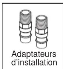
3-VALVE BYPASS SYSTEM
natural_image
Technical diagram of a mechanical assembly with arrows indicating direction (no text or labels)Turbine
natural_image
Mechanical assembly diagram showing a rotating shaft and base with directional arrows indicating motion (no text or symbols)natural_image
Technical line drawing of a mechanical component with no visible text or symbolsRISQUE LIÉ AU POIDS EXCESSIF
JOURS POUR VIDER LE SEL
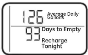
• DÉBIT EN GAL/MIN
Figure 17
Garant : MC Commercial Inc., Burlington, ON, L7R 5B6
Au Canada : Prodsupport.mabe.ca/crm/Products/ProductRegistration.aspx
LÍNEA DE DRENAJE FLEXIBLE
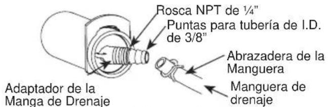
natural_image
Mechanical assembly diagram showing a multi-cranked lever mechanism with two downward arrows indicating motion or force (no text or symbols present)natural_image
Technical illustration of a mechanical assembly with multiple cylindrical components and a lever (no text or symbols)Figura 11
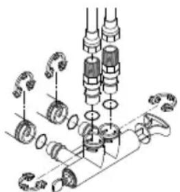
natural_image
Mechanical assembly diagram showing gears and shafts in a processing step (no text or labels)natural_image
Line drawing of a portable water heater with labeled parts (no text or symbols on the device itself)Figura 14
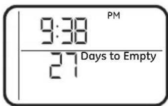
DÍAS HASTA VACIARSE
Figura 17
Louisville, KY 40225

- WATER SOFTENING SYSTEM
- OWNER'S MANUAL AND INSTALLATION INSTRUCTIONS
- ENGLISH/FRANÇAIS/ ESPAÑOL
- IMPORTANT SAFETY INFORMATION. READ ALL INSTRUCTIONS BEFORE USING
- SAFETY PRECAUTIONS
- WARNING
- Specifications and Performance Claims
- About the water softener system
- SERVICE
- AUTOMATIC HARD WATER BYPASS DURING RECHARGE
- FILL
- BRINING
- BRINE RINSE
- BACKWASH
- FAST RINSE
- NORMAL OPERATION, CONTROL DISPLAYS
- FEATURE: OPTIONAL RECHARGE CONTROLS
- RECHARGE TONIGHT
- RECHARGE NOW
- FEATURE: MEMORY
- FEATURE/SERVICE: AUTOMATIC ELECTRONIC DIAGNOSIS
- WATER CONDITION INFORMATION IRON
- SEDIMENT FILTER (BUILT IN)
- CHLORINE
- BEFORE YOU START
- TOOLS AND MATERIALS REQUIRED FOR INSTALLATION
- INSPECT SHIPMENT
- LOCATION REQUIREMENTS
- PLUMBING CODES
- AIR GAP REQUIREMENTS
- VALVE DRAIN REQUIREMENTS
- INLET/OUTLET PLUMBING REQUIREMENTS
- 3-VALVE BYPASS SYSTEM
- Installation Instructions
- Figure 6
- Figure 8
- TURN OFF WATER SUPPLY
- INSTALL BRINE TANK OVERFLOW ADAPTER
- INSTALL THE BYPASS VALVE
- MOVE WATER SOFTENER INTO PLACE
- GETTING ACCESS TO MAIN CONTROL BOARD
- (TO PLUG IN WATER SHUTOFF VALVE)
- INSTALL MOTORIZED WATER SHUTOFF VALVE
- CAUTION
- MOTORIZED WATER SHUTOFF VALVE
- COMPLETE INLET AND OUTLET PLUMBING
- INSTALLING THE GROUND WIRE
- INSTALL VALVE DRAIN HOSE
- INSTALL BRINE TANK (SALT STORAGE) OVERFIOW HOSE
- RINSE OUT CARBON FINES
- TEST FOR LEAKS
- ADD WATER AND SALT TO THE SALT STORAGE TANK
- EXCESSIVE WEIGHT HAZARD:
- PLUG IN THE WATER SOFTENER
- SANITIZE THE WATER SOFTENER / SANITIZE AFTER SERVICE
- Programming the Water Softener
- CONTROL OPERATION:
- SET TIME OF DAY
- SET WATER HARDNESS NUMBER
- SET RECHARGE (STARTING) TIME
- SET SALT LEVEL
- DAYS TO EMPTY
- START A RECHARGE
- Appliance Communication: WiFi Connect
- (For customers in the United States, its Territories, and Canada)
- OPTIONAL CONTROL SETTINGS
- LOW SALT ALARM
- SALT EFFICIENCY
- PRERINSE
- BACKWASH AND FAST RINSE
- FEATURE: OTHER DATA DISPLAY
- • CAPACITY REMAINING
- • AVERAGE DAILY
- - FLOW RATE, GPM
- RESETTING TO FACTORY DEFAULT
- POWER OUTAGE MEMORY
- BLUE INDICATOR LIGHT
- LOW SALT SIGNAL
- ERROR SIGNALS
- ADJUSTING YOUR WATER HARDNESS
- To make adjustments to water hardness:
- CHECKING THE SALT STORAGE LEVEL and REFILL
- ADDING SALT
- Water softening
- CLEANING IRON OUT OF THE WATER SOFTENING SYSTEM
- Routine Maintenance
- CLEANING THE NOZZLE AND VENTURI ASSEMBLY
- A clean nozzle and venturi is needed for the water softening system to work properly.
- BREAKING A SALT BRIDGE
- IMPORTANT: Be sure small holes in the gasket are centered directly over the small holes in the nozzle and venturi housing.
- Before you call for service
- Troubleshooting Tips
- NO SOFT WATER – Most Common Problems:
- Advanced troubleshooting for service
- AUTOMATIC ELECTRONIC
- DIAGNOSTICS
- Procedure for removing error code from display:
- MANUAL INITIATED ELECTRONIC DIAGNOSTICS
- Service: Manually Advance Recharge Check
- Exploded View/Parts List
- GXSHC40N
- FOR IOWA USE ONLY
- Notes
- Water Softening System Limited Warranty (For Customers in the U.S.)
- What Is Not Covered:
- Water Softening System Limited Warranty (For Customers in the Canada)
- Consumer Support
- GE Appliances Website
- Register Your Appliance
- Schedule Service
- Extended Warranties
- Parts and Accessories
- Contact Us
- D'ADOUCISSEMENT D'EAU SYSTÈME
- RISQUE LIÉ AU POIDS EXCESSIF
- JOURS POUR VIDER LE SEL
- LÍNEA DE DRENAJE FLEXIBLE
- DÍAS HASTA VACIARSE
Brand : Café
Model : GXSHC40N
Category : Water Softener