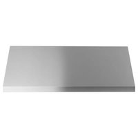
UVW9484SPSS - Range hood Café - Free user manual and instructions
Find the device manual for free UVW9484SPSS Café in PDF.


| Brand | Café |
| Model | UVW9484SPSS |
| Product Type | Range hood |
| Width | 48 in (121.9 cm) |
| Net Weight | 36 kg (80 lb) approximately |
| Power Supply | 120 V, 60 Hz, 15 A |
| Number of Speeds | 4 (Low, Medium, High, Boost) |
| QuietBoost Technology | Yes (optimized silent motor) |
| Wi-Fi Connectivity | Yes (via SmartHQ app) |
| Chef Connect Connectivity (Bluetooth) | Yes |
| Lighting | LED with night light mode |
| Material | Stainless steel |
| Filter Type | Dishwasher-safe metal baffle filters |
| Grease Collection Cups | Yes, dishwasher-safe |
| Charcoal Filter | Optional (ref. UXCF91) for recirculation |
| Delayed Shut-Off Function | Yes (15 minutes) |
| Boost Function | Yes (15 minutes) |
| Exhaust Duct | Round 10 in (254 mm) recommended |
| Installation | Wall-mounted or under cabinet |
| Recirculation Possible | Yes (optional kit) |
| Warranty | Limited 1 year |
Frequently Asked Questions - UVW9484SPSS Café
User questions about UVW9484SPSS Café
0 question about this device. Answer the ones you know or ask your own.
Ask a new question about this device
Download the instructions for your Range hood in PDF format for free! Find your manual UVW9484SPSS - Café and take your electronic device back in hand. On this page are published all the documents necessary for the use of your device. UVW9484SPSS by Café.
USER MANUAL UVW9484SPSS Café
SAFETY INFORMATION....3
USING THE HOOD
Controls....5
Chef Connect 6
Wi-Fi Connect 6
CARE AND CLEANING
Filters 7
Surfaces 8
Lights 8
INSTALLATION
INSTRUCTIONS 9
TROUBLESHOOTING TIPS 25
LIMITED WARRANTY 26
ACCESSORIES 27
CONSUMER SUPPORT 28
OWNER'S MANUAL & INSTALLATION INSTRUCTIONS
UVW9304
UVW9364
UVW9484
Write the model and serial numbers here:
Model # ____
Serial # ____
You can find them on a label on the inside of the hood.
THANK YOU FOR MAKING GE APPLIANCES A PART OF YOUR HOME.
Whether you grew up with GE Appliances, or this is your first, we're happy to have you in the family.
We take pride in the craftsmanship, innovation and design that goes into every GE Appliances product, and we think you will too. Among other things, registration of your appliance ensures that we can deliver important product information and warranty details when you need them.
Register your GE appliance now online. Helpful websites and phone numbers are available in the Consumer Support section of this Owner's Manual. You may also mail in the pre-printed registration card included in the packing material.

GE APPLIANCES
IMPORTANT SAFETY INFORMATION READ ALL INSTRUCTIONS BEFORE USING
WARNING
TO REDUCE THE RISK OF FIRE, ELECTRIC SHOCK OR INJURY TO PERSONS, OBSERVE THE FOLLOWING:
A. Use this unit only in the manner intended by the manufacturer. If you have questions, contact the manufacturer.
B. Before servicing or cleaning unit, switch power off at service panel and lock the service disconnecting means to prevent power from being switched on accidentally. When the service disconnecting means cannot be locked, securely fasten a prominent warning device, such as a tag, to the service panel.
C. Do not use this unit with any solid-state speed control device.
D. This unit must be grounded.
E. Do not use replacement parts that have not been recommended by the manufacturer (e.g. parts made at home using a 3D printer).
F. People who are not physically or mentally capable (including children), or who lack experience and knowledge, should not use this device unless they are supervised or instructed in its use by someone responsible for their safety.
G. Children must be supervised to ensure they do not treat this device as a toy.
H. Do not flambé under the range hood.
CAUTION
FOR GENERAL VENTILATING USE ONLY. DO NOT USE TO EXHAUST HAZARDOUS OR EXPLOSIVE MATERIALS AND VAPORS.
CAUTION
LIGHTS AND OTHER ACCESSIBLE PARTS MAY BECOME HOT DURING USE. ALLOW LIGHTS TO COOL BEFORE TOUCHING.
WARNING
TO REDUCE THE RISK OF A RANGE TOP GREASE FIRE:
A. Never leave surface units unattended at high settings. Boil overs cause smoking and greasy spillovers that may ignite. Heat oils slowly on low or medium settings.
B. Always turn hood ON when cooking on high heat or when flambéing food (i.e. Crepes Suzette, Cherries Jubilee, Peppercorn Beef Flambé).
C. Clean ventilating fans frequently. Grease should not be allowed to accumulate on fan or filter.
D. Use proper pan size. Always use cookware appropriate for the size of the surface element.
WARNING
TO REDUCE THE RISK OF INJURY TO PERSONS IN THE EVENT OF A RANGE TOP GREASE FIRE, OBSERVE THE FOLLOWING*:
A. SMOTHER FLAMES with a close-fitting lid, cookie sheet or metal tray, then turn off the burner. BE CAREFUL TO PREVENT BURNS. If the flames do not go out immediately, EVACUATE AND CALL THE FIRE DEPARTMENT.
B. NEVER PICK UP A FLAMING PAN—You may be burned.
C. DO NOT USE WATER, including wet dishcloths or towels—a violent steam explosion will result.
D. Use an extinguisher ONLY if:
- You know you have a Class ABC extinguisher, and you already know how to operate it.
- The fire is small and contained in the area where it started.
- The fire department is being called.
- You can fight the fire with your back to an exit.
* Based on "Kitchen Fire Safety Tips" published by NFPA.
READ AND SAVE THESE INSTRUCTIONS
IMPORTANT SAFETY INFORMATION READ ALL INSTRUCTIONS BEFORE USING
How to Remove Protective Shipping Film and Packaging Tape
Carefully grasp a corner of the protective shipping film with your fingers and slowly peel it from the appliance surface. Do not use any sharp items to remove the film. Remove all of the film before using the appliance for the first time.
To assure no damage is done to the finish of the product, the safest way to remove the adhesive from packaging tape on new appliances is an application of a household liquid dishwashing detergent. Apply with a soft cloth and allow to soak.
NOTE: The adhesive must be removed from all parts.
PROPER DISPOSAL OF YOUR APPLIANCE
Dispose of or recycle your appliance in accordance with Federal and Local Regulations. Contact your local authorities for the environmentally safe disposal or recycling of your appliance.
![graph TD A["1"] --> B["2"] B --> C["3"] C --> D["4"] D --> E["5"] E --> F["6"] G["Off"] --> H["Low Med"] H --> I["High Light"] I --> J["-WiFi"] K["Delay Off Hold 3 Sec"] --> L["WiFi Pairing"] M["Boost Hold 3 Sec"] --> N["Chef Connect To Pair Hold 3 Sec"]](/content/2026/05/1091294/images/b9f444127f6f7185d8f428ffb3658ee9b401ad997f2e205e44c6f50ed182c79a.jpg)
- Rangehood Control Panel: The control panel is located under the front edge of the canopy. The position and function of each control button are noted below.
- Fan On/Off: On/Off switch for the fan. The fan can be operated by pressing any of the fan setting buttons. Hold Power for 3 seconds to activate Delay Off feature, which automatically turns the fan off after 15 minutes. Low, Med and High buttons LEDs will rolling blink to indicate Delay Off feature is activated.
- Fan Settings: Speed control for fan. Fan speed is powered by QuietBoost™ Technology. This unique technology is designed to minimize ventilation noise and enhance motor efficiency for a peacefully-quiet, odor-free kitchen. Press the button Low for LOW speed, Med for MEDIUM speed, and High for HIGH speed. Hold down the High button for 3 seconds to activate the Boost speed that will run for 15 minutes. High button LED will blink on/off to indicate Boost feature is activated.
Light: Off/On/Night Light switch for the LED lights. Press the Light button to turn the lights on, again to set the lights to night light setting, and again to turn the lights off.
- Chef Connect: This is a Bluetooth® pairing feature for use with other compatible Chef Connect enabled products on a cooktop or range. When the device is paired, the default sync settings will be activated upon receiving a command from the range or cooktop. To change the default sync setting, refer to the Chef Connect section.
s To pair devices, hold down the Light button for 3 seconds. To turn it back off, hold the button down for another 3 seconds. See the Chef Connect section for more details. - IR Sensor: Remote control receiver when used with remote control kit.
- Wi-Fi: Hold down the Low button for 3 seconds to initiate the Wi-Fi connection. The Wi-Fi indicator light turns on when connected, see the Wi-Fi Connect section for details.
Chef Connect
Chef Connect Operation Bluetooth® Connection
To pair with another device:
To start the pairing process on the hood, press and hold the Light button for 3 seconds. The backlight for all the icons will flash until the hood is paired with the range or other device. If the pairing is successful, the backlights of all buttons will flash simultaneously three times and then turn off. The hood lights and fan default sync setting will be activated.
It will time out after 2 minutes if the pairing is not completed, after which the pairing sequence will need to be restarted.
To cancel pairing:
To cancel the pairing, hold the Light button down for 3 seconds and then turn off the hood.
Default Sync Settings:
The factory default setting for the light will be the brightest.
The factory default setting for the fan sync will be OFF.
The user can change the Default Sync Settings by pressing and holding the Med button for 3 seconds. This will enter the Default Settings Mode. Once in this mode, the backlights for all buttons will blink on/off indefinitely and the fan and light will switch to the current Default Sync Setting, so the user knows what the current default value is. At this time, set the light and fan to the desired default levels. Once the user is satisfied with the selection, press and hold the Power button for 3 seconds. This will exit this mode. At that time the backlights will stop blinking and the state of the fan and light will change back to their prior state before entering the Default Settings Mode.
Wi-Fi Connect
Connecting Your Wi-Fi Enabled Hood
Your hood is designed to provide you with two-way communication between your appliance and smart devices. By using the SmartHQ™ mobile app, you will be able to control hood operations such as fan speed, light intensity, and night light scheduling using your smartphone or tablet*.
For the best experience, prior to beginning:
- Download the SmartHQ™ app and sign in or create an account.
NOTE: New users must verify their email address to complete the sign in process.
- Have your home Wi-Fi network password available.
To connect your range to Wi-Fi, touch and hold the Low button for 3 seconds. The Wi-Fi indicator light will start flashing. Once your hood is connected, launch the SmartHQ™ app and tap on your hood to explore. Apply all software upgrades if prompted to ensure your hood has the latest features. If you have issues with the connection process, please call 800.220.6899 and ask for assistance with wireless connectivity.
* Compatible Apple or Android devices and home Wi-Fi network required.
Filters
Be sure the circuit breaker is off and all surfaces are cool before cleaning or servicing any part of the vent hood.
The baffle filters and drip trays are dishwasher safe and should be cleaned every month, depending on the usage of the hood
Grease Drip Tray
To install:
Place and seat the drip trays into the designated hood track. Slide them left or right until all trays are side-by-side in place in the track.
To remove:
Carefully, use the grease tray lip to lift the tray upwards and out. The tray will be free of the designated hood track.
To clean:
Swish the drip tray in hot soapy water and rinse in clean water or wash it in the dishwasher. Do not use abrasive cleaners.
NOTE: Some discoloration of the grease drip tray may occur in the dishwasher.

Drip Tray Replacement
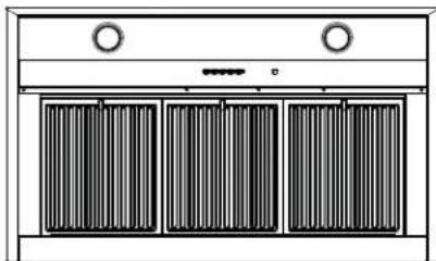
Baffle Grease Filter
The baffles channel grease released by foods on the cooktop into the drip trays. The baffles also help prevent flaming foods on the cooktop from damaging the inside of the hood.
The baffles must ALWAYS be in place when the hood is in use.
To install:
- Place the two tabs on the filter edge into the locating slots in the left or right side of the hood opening.
- Push the filter up, open the filter lock and snap it into place in the hood.
To remove:
Grasp the filter lock and pivot it open to release. Pull the filter down and out.
It is important for baffles to be placed correctly to channel grease to the drip trays and avoid grease accumulation in the baffles.
To clean:
Swish the filter in hot soapy water and rinse in clean water or wash it in the dishwasher. Do not use abrasive cleansers.
NOTE: Some discoloration of the filter may occur in the dishwasher.
To clean hard to reach areas of the filter, use a soft brush.

Baffle Replacement
Filters (Cont.)
Charcoal Filter (for recirculation installation on select models only)
NOTE: DO NOT rinse, or put charcoal filter in an automatic dishwasher.
The charcoal filter is NOT included with the unit. Order Charcoal Filter UXCF91. It cannot be cleaned; it must be replaced. It is recommended that the charcoal filter be replaced every 6 months or if it is noticeably dirty or discolored.
To reduce the risk of fire and shock, when used in recirculation mode, use only charcoal filter UXCF91.
To inquire about purchasing replacement charcoal filters or to find the location of a dealer nearest you, please call our toll-free number:
National Parts Center 800.626.2002
To Install
- Remove the grease filters. See Filters section.
- Install the charcoal filter mounts to either side of the motor using three screws per side.
-
Insert the tab on the charcoal filter into the triangular slot on the mount.
-
Clip the charcoal filter in until it is locked
- Repeat with second filter on the other side of the motor.
- Reattach the metal filters. See Filters section.
To Remove
- Remove grease filters-See Filters section
- Unclip the charcoal filter by pressing the release clip.
- Carefully remove charcoal filter from tab.

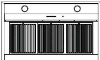
Surfaces
Stainless Steel Surfaces (on some models)
Do not use a steel wool pad; it will scratch the surface.
To clean the stainless steel surface, use warm sudsy water or a stainless steel cleaner or polish. Always wipe the surface in the direction of the brush line. Follow the cleaner instructions for cleaning the stainless steel surface. Cleaners with oxalic acid such as Bar Keepers
Friend Soft Cleanser™ will
remove surface rust, tarnish, and small blemishes. To receive a coupon for a trial sample of Bar Keepers Friend Soft Cleanser™ follow the link below or scan the QR Code.
barkeepersfriend.com/ge

Use only a liquid cleanser free of grit and rub in the direction of the brush lines with a damp soft sponge.
To inquire about purchasing stainless steel appliance cleaner or polish, or to find the location of a dealer nearest you, please visit geappliances.com/parts
Lights
To change the LED lamps, schedule a service appointment. See Consumer Support page for a list of websites and contact information.
If you have questions, visit GEAppliances.com, or call GE Appliances at 833-4BODEWELL (833-426-3393).
BEFORE YOU BEGIN
Read these instructions carefully and completely.
- IMPORTANT – Save these instructions for local inspector's use.
■IMPORTANT – Observe all governing codes and ordinances.
■ Note to Installer – Be sure to leave these instructions with Consumer.
■ Note to Consumer – Keep these instructions for future reference.
■ Skill level – Installation of this appliance requires a qualified installer or electrician.
■ Completion time – Approximately 1 to 3 hours
■ Proper installation is the responsibility of the installer.
■ Product failure due to improper installation is not covered under Warranty.
WARNING
TO REDUCE THE RISK OF FIRE,
ELECTRIC SHOCK OR INJURY TO PERSONS, OBSERVE THE FOLLOWING:
■ Installation work and electrical wiring must be done by qualified person(s) in accordance with all applicable codes and standards, including fire-rated construction.
- Sufficient air is needed for proper combustion and exhausting of gases through the flue (chimney) of fuel burning equipment to prevent back drafting. Follow the heating equipment manufacturer's guidelines and safety standards such as those published by the National Fire Protection Association (NFPA), the American Society for Heating, Refrigeration and Air Conditioning Engineers (ASHRAE) and the local code authorities. When applicable, install any makeup (replacement) air system in accordance with local building code requirements. Visit GEAppliances.com for available makeup air solutions.
■ When cutting or drilling into wall or ceiling, do not damage electrical wiring and other hidden utilities.
■ Ducted fans must always be vented to the outdoors.
■ Local codes vary. Installation of electrical connections and grounding must comply with applicable codes. In the absence of local codes, the vent should be installed in accordance with National Electrical Code ANSI/NFPA 70-1990 or latest edition.
WARNING
TO REDUCE THE RISK OF FIRE,
USE ONLY METAL DUCTWORK.
CAUTION
To reduce the risk of fire and to
properly exhaust air, be sure to duct air outside-do not vent exhaust air into spaces within walls or ceilings or into attics, crawl spaces, or garages. Ductwork used for this range hood shall be independent of other exhaust systems.
OPTIONAL POWER CORD KIT JXHC1
Use only with rangehood cord-connection kits that have been investigated and found acceptable for use with this model rangehood. An optional power cord kit, model JXHC1, is available at extra cost from your GE Appliances supplier for installation using a standard 3-prong, grounded wall outlet. Follow the installation instructions packed with the power cord to the range hood.
CAUTION
Due to the weight and size of these vent hoods and to reduce the risk of personal injury or
damage to the product, TWO PEOPLE ARE REQUIRED FOR PROPER INSTALLATION.
PRODUCT DIMENSIONS

30" Models
Requires a 30" opening.
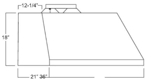
36" Models
Requires a 36" opening.

48" Models
Requires a 48" opening.
Installation Preparation
TOOLS AND MATERIALS REQUIRED (NOT SUPPLIED)

Pencil and tape measure

Safety glasses

Level

Phillips screwdriver with at least 6" shank
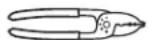
Wire cutter/stripper

Electric drill with #2 Phillips with 1/8" and 5/16" drill bits
Aluminized duct tape

UL listed wire nuts

Strain relief for junction box, 1" diameter knockout

8" round duct for 30" and 36" models
10" round duct for 48" model
Gloves
REMOVE THE PACKAGING
CAUTION
Wear gloves to protect against
sharp edges.
■ Remove the hood body.
■ Remove the hardware bag, literature package and other boxed parts.
■ Remove and properly discard the protective plastic wrapping and other packaging materials.
■ Consider recycling options for your appliance packaging material.
PLAN THE INSTALLATION
CAUTION
To reduce risk of fire and to
properly exhaust air, be sure to duct the air outside. Do not vent exhaust air into spaces within walls or ceilings or into attics, crawl spaces, or garages.
PARTS SUPPLIED FOR INSTALLATION
■ 1 Hardware Package
■ 1 Literature Package
■ 1 Strain Relief
■ 1 Wall or Roof Cap (Follow local codes and ordinances.)
■ All Metal Ductwork
PARTS NEEDED FOR INSTALLATION
WARNING
PERSONAL INJURY HAZARD
Because of the weight and size of the rangehood canopy. It is recommended that 2 people are used to install the range hood. Failure to properly lift rangehood could result in damage to the product or personal injury.
NOTE: Before making any cuts or holes for installation, determine which venting method will be used and carefully calculate all measurements.
Installation Preparation
PARTS PROVIDED
Locate the parts packed with the hood.

Top Damper

Motor
(2 with 48" model)
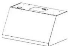
Hood Body

Grease Drip Trays

2 Baffle Filters
3 with 36" models
4 with 48" model

Wooden Installation Bar
HARDWARE PACKAGE
Locate and check contents.

A

(QTY: 4) 8 x 1-3/4 AB Screw. Used to mount the installation bar. Use 1/8" drill for pilot hole.
B

(QTY: 4) 2.9mm x 6mm
PZ screws. Used to attach the damper
D

(QTY: 4 or 8) M4 screws. Used to mount motor
C

(QTY: 2) 3/16" dry wall anchors with screws. Used for hood bottom mounting screw holes. Use 5/16" drill for pilot hole.
DUCT COVER REQUIREMENTS
Duct cover kits must be purchased separately. We recommend that the vent hood and duct cover (if used) be on site before final framing and wall finishing. This will help to accurately locate studs, ductwork and electrical service.

- Duct cover accessory comes with a lower and upper duct cover and installation hardware.
- The installation hardware includes mounting brackets to secure duct covers to the wall.
- For vented installations, recirculation holes can be hidden by installing the upper duct cover upside down.
- For ceiling installations up to 8' 4", use the 8' Ceiling Duct Cover kit CX8DC9SPSS. This kit only supports vented installation mode.
- For ceiling installations up to 11' 4", use the 10' High Ceiling Duct Cover kit CX10DC9SPSS.
- For higher ceiling installations up to 13' 2", use the 12' High Ceiling Duct Cover kit CX12DC9SPSS.
INSTALLATION DIMENSIONS
The hood duct covers can be adjusted for different ceiling heights depending on the distance between the bottom of the hood and the cooktop (distance X). See Installation Height Table on the next page.
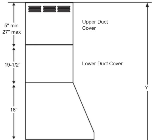
| Required Min & Recommended Max Ceiling Height Examples for 10' Duct Cover Kit (Vented) | ||
| Electric Gas | ||
| = 24" Y = Min 8' 2" Max 9'10" | = 30" Y = Min 8' 10" Max 10' 6" | = 36" Y = Min 9' 4" Max 11' 0" |
X = Distance from hood to cooktop. (Varies depending on the installation) Required 24" minimum over electric range or 30" minimum over gas range. The recommended maximum is 36".

Installation Preparation
INSTALLATION HEIGHT TABLE
| CX8DC9SPSS | ||
| Ceiling Duct Cover up to 8 ft. | ||
| Installation over Gas Range | Installation over Electric Range | |
| Ceiling Height (ft./in.) | Vented Installation Height | Vented Installation Height |
| 7' 0" | 24 | |
| 7' 1" | 24-25 | |
| 7' 2" | 24-26 | |
| 7' 3" | 25-27 | |
| 7' 4" | 26-28 | |
| 7' 5" | 27-29 | |
| 7' 6" | 28-30 | |
| 7' 7" | 29-31 | |
| 7' 8" 30 | 30-32 | |
| 7' 9" | 30-31 | 31-33 |
| 7' 10" | 30-32 | 32-34 |
| 7' 11" | 31-33 | 33-35 |
| 8' 0" | 32-34 | 34-36 |
| 8' 1" | 33-35 | 35-36 |
| 8' 2" | 34-36 | 36 |
| 8' 3" | 35-36 | |
| 8' 4" 36 | ||
| CX10DC9SPSS | ||||
| High Ceiling Duct Cover up to 10 ft. | ||||
| Installation over Gas Range | Installation over Electric Range | |||
| Ceiling Height (ft./in.) | Recirc Installation Height | Vented Installation Height (Recirc holes hidden) | Recirc Installation Height | Vented Installation Height (Recirc holes hidden |
| 8' 2" | 24 | |||
| 8' 3" | 25 | |||
| 8' 4" | 26 | |||
| 8' 5" | 27 | |||
| 8' 6" | 28 | |||
| 8' 7" | 29 | |||
| 8' 8" | 24 | 24, 30 | ||
| 8' 9" | 24-25 | 24-25, 31 | ||
| 8' 10" | 30 | 24-26 | 24-26, 32 | |
| 8' 11" | 30-31 | 24-27 | 24-27, 33 | |
| 9' | 30-32 | 24-28 | 24-28, 34 | |
| 9' 1" | 30-33 | 24-29 | 24-29, 35 | |
| 9' 2" | 30-34 | 24-30 | 24-30, 36 | |
| 9' 3" | 30-35 | 24-31 | 24-31 | |
| 9' 4" | 30 | 30-36 | 24-32 | 24-32 |
| 9' 5" | 30-31 | 24-33 | 24-33 | |
| 9' 6" | 30-32 | 24-34 | 24-34 | |
| 9' 7" | 30-33 | 24-35 | 24-35 | |
| 9' 8" | 30-34 | 24-36 | 24-36 | |
| 9' 9" | 30-35 | |||
| 9' 10" | 30-36 | |||
| 9' 11" | 25-36 | |||
| 10' | 26-36 | |||
| 10' 1" | 27-36 | |||
| 10' 2" | 28-36 | |||
| 10' 3" | 25-36 | 29-36 | ||
| 10' 4" | 26-36 | 30-36 | ||
| 10' 5" | 27-36 | 31-36 | ||
| 10' 6" | 28-36 | 32-36 | ||
| 10' 7" | 31-36 | 29-36 | 33-36 | |
| 10' 8" | 32-36 | 30-36 | 34-36 | |
| 10' 9" | 33-36 | 31-36 | 35-36 | |
| 10' 10" | 34-36 | 32-36 | 36 | |
| 10' 11" | 31-36 | 35-36 | 33-36 | |
| 11' | 32-36 36 | 34-36 | ||
| 11' 1" | 33-36 | 35-36 | ||
| 11' 2" | 34-36 | 36 | ||
| 11' 3" | 35-36 | |||
| 11' 4" | 36 | |||
| CX12DC9SPSS | ||||
| High Ceiling Duct Cover up to 12 ft. | ||||
| Installation over Gas Range | Installation over Electric Range | |||
| Ceiling Height (ft./in.) | Recirc Installation Height | Vented Installation Height (Recirc holes hidden) | Recirc Installation Height | Vented Installation Height (Recirc holes hidden |
| 9' 1" | -25 | |||
| 9' 2" | ||||
| 9' 3" 24 | ||||
| 9' 4" 24 | ||||
| 9' 5" 24 | 24-26 | |||
| 9' 6" 24 | -25 24-27 | |||
| 9' 7" 24 | -26 24-28 | |||
| 9' 8" 24 | -27 24-29 | |||
| 9' 9" 24 | -28 24-30 | |||
| 9' 10" 24 | -29 24-31 | |||
| 9' 11" 30 | 24-30 24-32 | |||
| 10' 0" 30 | -31 24-31 24 | -33 | ||
| 10' 1" 30 | 30-32 24-32 | 24-34 | ||
| 10' 2" 30 | -31 30-33 24 | -33 24-35 | ||
| 10' 3" 30 | -32 30-34 24 | -34 | 24-36 | |
| 10' 4" 30 | -33 30-35 24 | -35 | ||
| 10' 5" 30 | -34 | 30-36 | 24-36 | |
| 10' 6" 30 | -35 | |||
| 10' 7" | 30-36 | |||
| 10' 8" | ||||
| 10' 9" | ||||
| 10' 10" | ||||
| 10' 11" | ||||
| 11' | ||||
| 11' 1" | ||||
| 11' 2" | ||||
| 11' 3" | ||||
| 11' 4" | ||||
| 11' 5" | ||||
| 11' 6" | ||||
| 11' 7" | ||||
| 11' 8" | ||||
| 11' 9" | 25-36 | |||
| 11' 10" | 26-36 | |||
| 11' 11" | 27-36 | |||
| 12' | 28-36 | |||
| 12' 1" 25 | -36 29-36 | |||
| 12' 2" 26 | -36 30-36 | |||
| 12' 3" 27 | -36 31-36 | |||
| 12' 4" 28 | -36 32-36 | |||
| 12' 5" 31 | -36 29-36 31 | -36 | ||
| 12' 6" 32 | -36 30-36 32 | -36 | ||
| 12' 7" 33 | -36 31-36 33 | -36 | ||
| 12' 8" 34 | -36 32-36 34 | -36 | ||
| 12' 9" 35 | -36 35-36 35 | -36 | ||
| 12' 10" | 32-36 36 | 34-36 | ||
| 12' 11" | 33-36 | 35-36 | ||
| 13 | 34-36 | 36 | ||
| 13' 1" 35 | -36 | |||
| 13' 2" 36 | ||||
ADVANCE PLANNING
Duct Install Planning
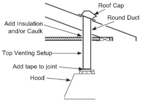
This hood is designed to be vented from the top of the hood. Use locally supplied elbows to vent through ceiling or through the rear wall. Use an 8" round duct for 30" and 36" models and a 10" round duct for 48" models.
■ Use metal ductwork only.
■ Plan the route for venting exhaust to the outdoors. To maximize the ventilation performance of the vent system:
- Minimize the duct run length and number of transitions and elbows.
- Maintain a constant duct size.
- Seal all joints with duct tape to prevent any leaks.
NOTE: Flexible vent is not recommended. Flexible vent creates back pressure and air turbulence that greatly reduces performance.
■ Maximum equivalent duct length for 100 CFM: 150 foot for vent hoods.
■ Installation of a wall or roof cap with damper at the exterior opening is recommended. Follow local codes and ordinances. Order the wall or roof cap and any transition and length of duct needed in advance.
- When applicable, install any makeup (replacement) air system in accordance with local building code requirements. 8" or 10" round duct universal make up air kit can be purchased locally. Vent system can terminate through the roof.
POWER SUPPLY
IMPORTANT – (Please read carefully)
WARNING
FOR PERSONAL SAFETY, THIS APPLIANCE MUST BE PROPERLY GROUNDED.
Remove house fuse or open circuit breaker before beginning installation.
Do not use an extension cord or adapter plug with this appliance. Follow National Electrical Codes or prevailing local codes and ordinances.
Electrical supply
These vent hoods must be supplied with 120V, 60Hz, and connected to a properly grounded branch circuit, and protected by a 15 or 20 amp circuit breaker or time delay fuse.
■ Wiring must be 2 wire with ground.
■ If the electrical supply does not meet the above requirements, call a licensed electrician before proceeding.
■ Route house wiring as close to the installation location as possible in the ceiling or wall.
■ Connect the wiring to the house wiring in accordance with local codes.
Grounding instructions
The grounding conductor must be connected to a ground metal, permanent wiring system, or an equipment-grounding terminal or lead on the hood.
WARNING
The improper connection of the equipment-grounding conductor can result in a risk of electric shock. Check with a qualified electrician or service representative if you are in doubt whether the appliance is properly grounded.
Installation Preparation
NEW CONSTRUCTION, PRE-PLANNING, OR REMODELING
NOTE: For existing instruction, skip to the next section.
FOR TOP VENTING
■ For ducted installation through the top, the 8" diameter hole (for 30" or 36" model) or the 10" diameter hole (for 48" model) for the duct in the ceiling must be center 6-1/4" away from the finished rear wall in the installation space.

DETERMINE HOOD, DUCTWORK AND WIRING LOCATIONS
- This hood can be installed onto the wall or underneath the soffit or cabinet.
- For installing the hood to soffit or cabinet, refer to page 19 for alternate mounting method.
- Measure desired distance from the bottom of the hood to the cooking surface, 24" minimum over electric range or 30" minimum over gas range and 36" recommended maximum.
- Use a level to draw a horizontal line indicating the bottom of the hood.
- Measure 14-7/8" up from the horizontal line indicating the bottom of the hood. Draw another horizontal line to indicate the bottom of the installation bar.
- Use a level to draw the cooktop or range centerline location.
For Ceiling Ducting:
- If venting out the ceiling, extend the centerline forward on the ceiling to the back wall.
- Measure 6-1/4" from back wall to mark center point.
- Cut 8" dia. duct hole from center point on the ceiling for 30" or 36" models.
- Cut 10" dia. duct hole from center point on the ceiling for 48" models.
Venting Through a Soffit or Cabinet:
- Follow the same procedure for ceiling ducting to cut the hole through the top of the soffit or cabinet.

House Wiring Location:
- The junction box is located inside the hood body on the left side. See Illustrations for hood knockout locations.
House wiring may enter the junction box from the rear or the top of the hood on the left side.
To route house wiring through the ceiling, soffit or cabinet:
- Cut a hole approximately 1-1/4" dia. forward on the ceiling at a distance (X) to the left of the centerline based on table below.


1 INSTALL HOOD SUPPORT
IMPORTANT: Framing must be capable of supporting 100 lbs for 30" and 36" models and 150 lbs for 48" models.
- Locate a minimum of 1 vertical stud for the installation bar by tapping drywall with a hammer or use a stud finder.
- Level the installation bar and center left to right above the marked line. Hold bar against the wall.
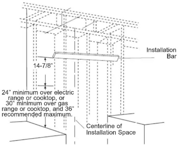
- Drill 1/8" pilot holes at the 2 locations through holes in the installation bracket, using a minimum of 1 vertical stud. Secure the installation bar with supplied screws (A) as shown above when using a stud. Secure with screw and wall anchor (C) if a second stud cannot be used.
Drill Bottom Mounting Hole Locations:
- Hang hood on installation bar to mark anchor locations. Mark hole locations through the back of the hood.
- If installing to the soffit or cabinet, hold the hood flush to the soffit or cabinet to mark screw hole locations.
- Remove the hood and drill 5/16" clearance holes centered at the marks you made.

1 INSTALL HOOD SUPPORT (Cont.)
- Install wall anchors (C) by tapping the anchors with a hammer to seat the teeth of the flanges into the wall. This keeps anchor from rotating.
- Drive the anchor screws until the barrels crimp against the inside of the wall.
- Remove the screws from the wall anchors before installing the hood.
2 INSTALL DAMPER
IMPORTANT: Remove shipping tape from damper and check that damper moves freely.
Install Top Damper:
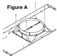
- The motor mounting plate comes pre-installed in the hood for top venting.
• Install the top damper to the hood body as shown in Figure A using screws (B) from top of hood.
3 INSTALL HOOD ONTO WALL
- Pull house wiring through knockout at the back or top of the hood.
- Lift the hood and place over the hooks on the installation bar. Allow the hood to slide down into position.
- Check to be sure the hood is level and centered.
- Tighten wall anchor screws (C) to finish hood body installation to the wall.
- Remove cover from junction box inside the hood.

4 (Alternate Mounting Method) INSTALL HOOD TO SOFFIT OR CABINET
SKIP THIS STEP IF USING WALL MOUNTING METHOD
IMPORTANT: Soffit or cabinet framing must be capable of supporting 100 lbs. for 30" and 36" models and 150 lbs. for 48" models.
When necessary the hood may be installed so that it is supported by the soffit or cabinet.
- The soffit should be constructed with 2"x4"'s.
- Use a level to draw the cooktop or range center line.
- Continue the centerline forward on the bottom of the soffit.
- Install horizontal wood supports between the 2"x4", at distance A to the left and right, as per the table below.

| “A”Center - line to Center Stud | “B”Opening for Ductwork for top venting | |
| 30”Models | 8-3/4” | 8-3/8” W x 11-1/4” H |
| 36”Models | 13-3/4” | |
| 48”Models | 17-3/4” | 10-5/8” W x 11-1/4” H |
4 (Alternate Mounting Method) INSTALL HOOD TO SOFFIT OR CABINET (Cont.)
- Drill two 1/8" pilot holes at a distance of 10" from the back wall in the horizontal wood supports. This is the vertical distance between mounting keyholes and back wall as shown in Figure C
- Drill two more 1/8" pilot holes at a distance of 3" from the back wall in the horizontal wood supports. This is the vertical distance between mounting screw holes and back wall as shown in Figure C.
- For top venting, allow minimum opening (Dim. B) to accommodate damper in soffit or cabinet.

-
Drive mounting Screw (A) into the studs until they protrude 1/4". This 1/4" gap will provide clearance to engage the keyhole slots in the top of the hood.
-
The hood must also be secured to the back wall. Follow instruction on page 18, "Drill Bottom Mounting Hole Locations" for installation to the back wall.
- Follow instructions on page 17 "House Wiring Locations" for wiring setup.
- Lift hood onto mounting screws. Slide back against the rear wall.
- Pull house wiring through the knockout at the rear or top of the hood.
- Tighten mounting screws (A).
- Once the hood is secured to the soffit or cabinet, drive screws (C) to secure the hood to the back wall.

5 INSTALL MOTOR
1) Align the motor exhaust with the top damper as shown in the Figure A for top venting.

II) Plug the motor connector into the mating connector on top of the control housing.
III) Repeat steps I through III for dual motor models.
IV) For dual motor models, secure the motor wires to the motor clips as shown in image below.

Dual Motor Top Venting Installation
Motor Mating
Connector Location
6 CONNECT ELECTRICAL
Verify that power is turned off at the source.
WARNING
If house wiring is not 2-wire with
a ground wire, a ground must be provided by the installer. When house wiring is aluminum, be sure to use UL approved anti-oxidant compound and aluminum-to-copper connectors.
- Remove junction box cover.


- Pull the house wiring through the knockout at the top or back of the hood and secure with the strain relief.

- Use UL listed wire nuts to connect incoming white to white, and black to black wires.
- Loosen the green grounding screw (with grounding bracket) in the junction box. Loop solid copper house wire clockwise around the green grounding screw and above the bracket. Firmly tighten the screw over the loop.

- Replace junction box cover and ensure wires are not pinched.
NOTE:
For corded installation: Use only with rangehood cord-connection kits that have been investigated and found acceptable for use with this model rangehood.
7 CONNECT DUCTWORK
A. Vented Installation
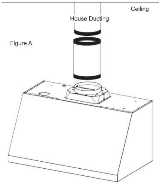
- Connect the house ducting to the top damper as shown in Figure A.
- Seal all connections with duct tape.
CAUTION
Do not use sheet metal screws at the transition to ductwork connection. Doing so will prevent proper damper operations. Seal connection with tape only.
B. Recirculation (non-vented) Installation
NOTE: A recirculation duct (WB34X30519), and Charcoal Filter (UXCF91), are not included with the hood and are necessary for recirculation installation.
- Attach the recirculation duct to the duct cover mounting bracket with screws provided.
- Connect the ducting from the exhaust outlet on the hood to the recirculation duct. Use duct tape to seal the connections.

NOTE: Recirculation installation does not apply to 48" models.
8 INSTALL DUCT COVERS
- Refer to section "Duct Cover Requirements" on page 13 for duct cover accessory part numbers.
- Follow instructions included with the duct cover accessory to install duct covers.
9 INSTALL GREASE TRAYS AND FILTERS
- Remove protective film.
- Insert the two back tabs of each filter into the back edge of the good body.
- Push the button on the latch to open the latch.
- Install the front edge on the filter into the front edge of the hood body.
- Release the latch, making sure it is fully engaged by hearing a click of the latch and the button is fully released.

MAKE UP AIR TECHNOLOGY
This operation must be performed by a qualified technician or installer.
Note to Installers and Inspectors: This product comes equipped with a simple installation feature that limits maximum CFM levels in order to comply with certain local codes or regulations. This installation method may not be necessary for all installations, please refer to your local codes for further guidelines.
This makeup air feature applies to single motor models only.
CAUTION
Hood must be disconnected from main power prior performing the conversion instructions
listed below. Failure to do so could result in personal injury or damage to the product.
To modify unit (if needed for local codes):
390CFM
By design, the maximum blower speed is greater than 400 CFM. For local codes requiring reduced CFM, modify the wiring as described below:
- Remove the baffle filters.
- Disconnect all the harnesses from the top of control box located on right side of motor.
- Loosen the screws on top of control box and slide out to remove it from the hood.
- Uninstall the control box cover.
- For a maximum of 390 CFM Unit can operate with 4 speeds (Low, Medium, High, Boost).
i. Disconnect connectors of the BROWN wire.
ii. Remove the cap attached to the connector of the RED wire.
iii. Connect the mating connector of the BROWN wire and the RED wire.
iv. Attach the cap to the open BROWN wire connector.
-
Reinstall control box cover and secure control box to the bracket in the hood using the two screws.
-
Connect all harnesses on top of the control box.
-
Reinstall filters.
Note to Inspectors: To verify this product installation, check motor wiring connections as described above.


Factory Installed Wiring Setup
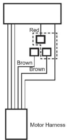
Max 390 CFM Boost Wiring Setup
Troubleshooting tips ... Before you schedule service
Save time and money! Review the chart below first and you may not need to schedule service.
| Problem Possible Cause What To Do | ||
| Fan/Light does not operate when button is turned ON | A house fuse may be blown or a circuit breaker tripped. | Replace fuse or reset circuit breaker. |
| Loud or abnormal airflow noise | Wrong duct size used in installation. This | hood requires 8" ducting or 10" ducting depending on model to perform optimally. Using smaller duct pipe will cause reduced venting. Minimize the duct run length and number of transitions and elbows. GE Appliances service technicians cannot correct this issue if installed improperly. |
| Fan fails to circulate air or moves air slower than normal and/or fan is making loud or abnormal airflow noise | Obstructions in duct work. Make sure nothing is blocking the vent. Make sure your wall or roof cap has a blade or door. | |
| Damper blade on wall or roof cap may not be open. | Make sure damper swings freely. Damper blades may flip over and will not fully open when this happens. Adjust to original position. | |
| Metal grease filter and charcoal filter (if present) may be dirty. | Clean the metal grease filter and replace charcoal filter (if present). See Care and Cleaning of the Vent Hood. | |
| Fan keeps going off and on | The motor is probably overheating and turning itself off. This can be harmful to the motor. | Check to be sure the filters are clean. If off and on cycling continues, call for service. |
| Hood will not work remotely | Router issues, no wireless signal, etc. For | assistance with hood wireless network connectivity, please call 800.220.6899. |
| Hood is not connected. | ||
Vented Range Hood Limited Warranty
GEAppliances.com
All warranty service is provided by our Factory Service Centers, or an authorized Customer Care® technician. To schedule service online, visit us at bodewell.com/schedule-repair-service, or call GE Appliances at 833-4BODEWELL (833-426-3393). Please have your serial number and your model number available when calling for service.
Servicing your appliance may require the use of the onboard data port for diagnostics. This gives a GE Appliances factory service technician the ability to quickly diagnose any issues with your appliance and helps GE Appliances improve its products by providing GE Appliances with information on your appliance. If you do not want your appliance data to be sent to GE Appliances, please advise your technician not to submit the data to GE Appliances at the time of service.
| For the period of GE Appliances will replace | |
| One yearFrom the date of the original purchase | Any part of the cooking product which fails due to a defect in materials or workmanship.During this limited one-year warranty, GE Appliances will provide, free of charge, all labor and related service costs to replace the defective part. |
What GE Appliances will not cover:
■ Service trips to your home to teach you how to use the product.
■ Improper installation, delivery, or maintenance.
■ Failure of the product if it is abused, misused, modified, or used for other than the intended purpose or used commercially.
■ Replacement of house fuses or resetting of circuit breakers.
■ Damage to the product caused by accident, fire, floods, or acts of God.
■ Damage to finish, such as surface rust, tarnish, or small blemishes not reported within 48 hours of delivery.
■ Incidental or consequential damage caused by possible defects with this appliance.
■ Damage caused after delivery.
■ Product not accessible to provide required service.
■ Service to repair or replace light bulbs, except for LED lamps.
EXCLUSION OF IMPLIED WARRANTIES
Your sole and exclusive remedy is product repair as provided in this Limited Warranty. Any implied warranties, including the implied warranties of merchantability or fitness for a particular purpose, are limited to one year or the shortest period allowed by law.
This limited warranty is extended to the original purchaser and any succeeding owner for products purchased for home use within the USA. If the product is located in an area where service by a GE Appliances Authorized Servicer is not available, you may be responsible for a trip charge or you may be required to bring the product to an Authorized GE Appliances Service location for service. In Alaska, the limited warranty excludes the cost of shipping or service calls to your home.
Some states do not allow the exclusion or limitation of incidental or consequential damages. This limited warranty gives you specific legal rights, and you may also have other rights which vary from state to state. To know what your legal rights are, consult your local or state consumer affairs office or your state's Attorney General.
Warrantor: GE Appliances, a Haier company, Louisville KY, 40225
In Canada (including the province of Québec):
This limited warranty is extended to the original purchaser and any succeeding owner for products purchased in Canada including Québec for home use within Canada including Québec. If the product is located in an area where service by a GE Appliances Authorized Servicer is not available, you may be responsible for a trip charge or you may be required to bring the product to an Authorized GE Appliances Service location.
Some provinces including Québec do not allow the exclusion or limitation of incidental or consequential damages. This limited warranty gives you specific legal rights, and you may also have other rights which vary from province to province including Québec. To know what your legal rights are, consult your local or provincial consumer affairs office.
For Québec consumers only - Notice on the warranty of availability of spare parts, repair services and information necessary for repair or maintenance (s. 39 of the Consumer Protection Act):
Please be advised that MC Commercial Inc. ("MC Commercial") does not guarantee, within the meaning of section 39 of the Consumer Protection Act, CQLR, c. P-40.1 and sections 79.18 to 79.20 of the Regulation respecting the application of the Consumer Protection Act, CQLR, c P-40.1, r. 3, the availability of replacement parts, repair services, or the information necessary for the maintenance or repair of goods manufactured, imported, advertised, or sold by MC Commercial.
Please note that MC Commercial Inc. continues to offer the manufacturer's limited warranty as stated in the Owner's Manual or Quick Guide, and that this limited warranty is distinct from the statutory warranty of availability provided for under section 39 of the Consumer Protection Act.
Warrantor: MC Commercial Inc., Burlington, ON, L7L 6B2
Extended Warranties: Purchase a GE Appliances extended warranty and learn about special discounts that are available while your warranty is still in effect. You can purchase it online anytime at
bodewellcareplan.com
GE Appliances Service will still be there after your warranty expires.
Looking For Something More?
GEAppliances.com offers a variety of accessories to improve your cooking and maintenance experiences!
Refer to the Consumer Support page for website information.
The following products and more are available:
Parts
| Baffle Filters |
| Grease Drip Trays |
| Duct Covers |
| Remote Control |
| 15" Cabinet Filler Panel |
| Power Cord Kit |
| Charcoal Filters |
| Recirculation Kit |
Cleaning Supplies
| Stainless Steel Wipes |
| Stainless Steel Appliance Cleaner |
| Bar Keepers Friend Soft CleanserTM |
Consumer Support
GE Appliances Website
Have a question or need assistance with your appliance? Try the GE Appliances Website 24 hours a day, any day of the year! You can also shop for more great GE Appliances products and take advantage of all our on-line support services designed for your convenience. GEAppliances.com
Register Your Appliance
Register your new appliance on-line at your convenience! Timely product registration will allow for enhanced communication and prompt service under the terms of your warranty, should the need arise. You may also mail in the pre-printed registration card included in the packing material. GEAppliances.com/register
Schedule Service
Expert GE Appliances repair service is only one step away from your door. Get on-line and schedule your service at your convenience any day of the year.
bodewell.com/schedule-repair-service or call 833-4BODEWELL (833-426-3393) during normal business hours.
Extended Warranties
Purchase a GE Appliances extended warranty and learn about special discounts that are available while your warranty is still in effect. You can purchase it on-line anytime. GE Appliances Services will still be there after your warranty expires. bodewellcareplan.com or call 800.626.2224 during normal business hours.
Remote Connectivity
For assistance with wireless network connectivity (for models with remote enable), visit our website at GEAppliances.com/connect or call 800.220.6899.
Parts and Accessories
Individuals qualified to service their own appliances can have parts or accessories sent directly to their homes (VISA, MasterCard and Discover cards are accepted). Order on-line today 24 hours every day.
GEApplianceparts.com or by phone at 877.959.8688 during normal business hours.
Instructions contained in this manual cover procedures to be performed by any user. Other servicing generally should be referred to qualified service personnel. Caution must be exercised, since improper servicing may cause unsafe operation.
Contact Us
If you are not satisfied with the service you receive from GE Appliances, contact us on our Website with all the details including your phone number, or write to:
General Manager, Customer Relations | GE Appliances, Appliance Park | Louisville, KY 40225
GEAppliances.com/contact or call 800.626.2000

Surfaces
DIMENSIONS DU PRODUIT

Corps de la hotte

Bacs à graisse
DIMENSIONS D'INSTALLATION
1 INSTALLATION DU SUPPORT DE HOTTE

Garant : GE Appliances, a Haier company, Louisville, KY 40225
Garant : MC Commercial Inc., Burlington, ON, L7L 6B2

Superficies
DIMENSIONES DEL PRODUCTO


Garante: MC Commercial Inc., Burlington, ON, L7L 6B2
General Manager, Customer Relations | GE Appliances, Appliance Park | Louisville, KY 40225
GEAppliances.com/contact o comuníquese al 800.626.2000

- SAFETY INFORMATION....3
- USING THE HOOD
- CARE AND CLEANING
- INSTALLATION
- TROUBLESHOOTING TIPS 25
- OWNER'S MANUAL & INSTALLATION INSTRUCTIONS
- THANK YOU FOR MAKING GE APPLIANCES A PART OF YOUR HOME
- IMPORTANT SAFETY INFORMATION READ ALL INSTRUCTIONS BEFORE USING
- WARNING
- CAUTION
- READ AND SAVE THESE INSTRUCTIONS
- PROPER DISPOSAL OF YOUR APPLIANCE
- CHEF CONNECT
- CHEF CONNECT OPERATION BLUETOOTH® CONNECTION
- TO PAIR WITH ANOTHER DEVICE
- TO CANCEL PAIRING
- DEFAULT SYNC SETTINGS
- WI-FI CONNECT
- CONNECTING YOUR WI-FI ENABLED HOOD
- FILTERS
- GREASE DRIP TRAY
- TO INSTALL
- TO REMOVE
- TO CLEAN
- BAFFLE GREASE FILTER
- FILTERS (CONT.)
- CHARCOAL FILTER (FOR RECIRCULATION INSTALLATION ON SELECT MODELS ONLY)
- NATIONAL PARTS CENTER 800.626.2002
- SURFACES
- STAINLESS STEEL SURFACES (ON SOME MODELS)
- LIGHTS
- BEFORE YOU BEGIN
- TO REDUCE THE RISK OF FIRE
- ELECTRIC SHOCK OR INJURY TO PERSONS, OBSERVE THE FOLLOWING
- USE ONLY METAL DUCTWORK
- OPTIONAL POWER CORD KIT JXHC1
- INSTALLATION PREPARATION
- TOOLS AND MATERIALS REQUIRED (NOT SUPPLIED)
- REMOVE THE PACKAGING
- PLAN THE INSTALLATION
- PARTS SUPPLIED FOR INSTALLATION
- PARTS NEEDED FOR INSTALLATION
- PERSONAL INJURY HAZARD
- PARTS PROVIDED
- HARDWARE PACKAGE
- DUCT COVER REQUIREMENTS
- INSTALLATION DIMENSIONS
- ADVANCE PLANNING
- DUCT INSTALL PLANNING
- POWER SUPPLY
- ELECTRICAL SUPPLY
- GROUNDING INSTRUCTIONS
- NEW CONSTRUCTION, PRE-PLANNING, OR REMODELING
- FOR TOP VENTING
- DETERMINE HOOD, DUCTWORK AND WIRING LOCATIONS
- FOR CEILING DUCTING
- VENTING THROUGH A SOFFIT OR CABINET
- HOUSE WIRING LOCATION
- TO ROUTE HOUSE WIRING THROUGH THE CEILING, SOFFIT OR CABINET
- 1 INSTALL HOOD SUPPORT
- DRILL BOTTOM MOUNTING HOLE LOCATIONS
- 1 INSTALL HOOD SUPPORT (CONT.)
- 2 INSTALL DAMPER
- INSTALL TOP DAMPER
- 3 INSTALL HOOD ONTO WALL
- 4 (ALTERNATE MOUNTING METHOD) INSTALL HOOD TO SOFFIT OR CABINET
- 4 (ALTERNATE MOUNTING METHOD) INSTALL HOOD TO SOFFIT OR CABINET (CONT.)
- 5 INSTALL MOTOR
- 6 CONNECT ELECTRICAL
- NOTE
- 7 CONNECT DUCTWORK
- VENTED INSTALLATION
- RECIRCULATION (NON-VENTED) INSTALLATION
- 8 INSTALL DUCT COVERS
- 9 INSTALL GREASE TRAYS AND FILTERS
- MAKE UP AIR TECHNOLOGY
- 390CFM
- TROUBLESHOOTING TIPS ... BEFORE YOU SCHEDULE SERVICE
- VENTED RANGE HOOD LIMITED WARRANTY
- GEAPPLIANCES.COM
- WHAT GE APPLIANCES WILL NOT COVER
- EXCLUSION OF IMPLIED WARRANTIES
- IN CANADA (INCLUDING THE PROVINCE OF QUÉBEC)
- FOR QUÉBEC CONSUMERS ONLY - NOTICE ON THE WARRANTY OF AVAILABILITY OF SPARE PARTS, REPAIR SERVICES AND INFORMATION NECESSARY FOR REPAIR OR MAINTENANCE (S. 39 OF THE CONSUMER PROTECTION ACT)
- BODEWELLCAREPLAN.COM
- LOOKING FOR SOMETHING MORE
- CONSUMER SUPPORT
- GE APPLIANCES WEBSITE
- REGISTER YOUR APPLIANCE
- SCHEDULE SERVICE
- EXTENDED WARRANTIES
- REMOTE CONNECTIVITY
- PARTS AND ACCESSORIES
- CONTACT US
- DIMENSIONS D'INSTALLATION
- 1 INSTALLATION DU SUPPORT DE HOTTE
- SUPERFICIES
Brand : Café
Model : UVW9484SPSS
Category : Range hood