CV48SSLSS - Coffee maker Café - Free user manual and instructions
Find the device manual for free CV48SSLSS Café in PDF.

User questions about CV48SSLSS Café
0 question about this device. Answer the ones you know or ask your own.
Ask a new question about this device
Download the instructions for your Coffee maker in PDF format for free! Find your manual CV48SSLSS - Café and take your electronic device back in hand. On this page are published all the documents necessary for the use of your device. CV48SSLSS by Café.
USER MANUAL CV48SSLSS Café
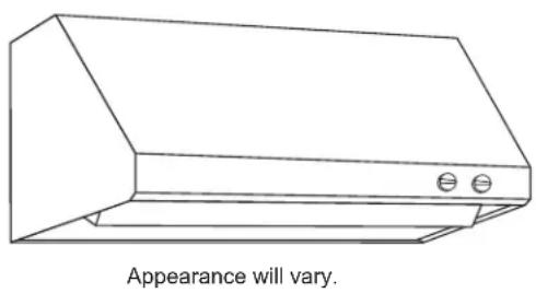
Stainless Steel Professional VENT HOOD
SAFETY INFORMATION .... 3
USING THE HOOD
Controls 5
Implement Holders .... 5
For your Safety 5
CARE AND CLEANING
Baffle Grease Filters and Drip Trays ..... 6
Stainless Steel Surfaces....7
Light Bulbs 7
INSTALLATION INSTRUCTIONS..8
TROUBLESHOOTING TIPS ..... 20
WARRANTY....22
ACCESSORIES 23
CONSUMER SUPPORT ...... 24
OWNER'S MANUAL & INSTALLATION INSTRUCTIONS
CV48S
Write the model and serial numbers here:
Model # ____
Serial # ____
You can find them on a label on the front panel of the unit.
ESPAÑOL
THANK YOU FOR MAKING GE APPLIANCES A PART OF YOUR HOME.
Whether you grew up with GE Appliances, or this is your first, we're happy to have you in the family.
We take pride in the craftsmanship, innovation and design that goes into every GE Appliances product, and we think you will too. Among other things, registration of your appliance ensures that we can deliver important product information and warranty details when you need them.
Register your GE appliance now online. Helpful websites and phone numbers are available in the Consumer Support section of this Owner's Manual. You may also mail in the pre-printed registration card included in the packing material.

GE APPLIANCES
IMPORTANT SAFETY INFORMATION READ ALL INSTRUCTIONS BEFORE USING
WARNING
TO REDUCE THE RISK OF FIRE, ELECTRIC SHOCK OR INJURY TO PERSONS, OBSERVE THE FOLLOWING:
A. Use this unit only in the manner intended by the manufacturer. If you have questions, contact the manufacturer.
B. Before servicing or cleaning unit, switch power off at service panel and lock the service disconnecting means to prevent power from being switched on accidentally. When the service disconnecting means cannot be locked, securely fasten a prominent warning device, such as a tag, to the service panel.
C. Do not use this unit with any solid-state speed control device.
D. This unit must be grounded.
CAUTION
FOR GENERAL VENTILATING USE ONLY. DO NOT USE TO EXHAUST HAZARDOUS OR EXPLOSIVE MATERIALS AND VAPORS.
CAUTION
To reduce risk of fire and to properly exhaust air, be sure to duct air outside. Do not vent exhaust air into spaces within walls or ceilings or into attics, crawl spaces, or garages.
WARNING
TO REDUCE THE RISK OF INJURY TO PERSONS IN THE EVENT OF A RANGE TOP GREASE FIRE, OBSERVE THE FOLLOWING*:
A. SMOTHER FLAMES with a close-fitting lid, cookie sheet or metal tray, then turn off the burner. BE CAREFUL TO PREVENT BURNS. If the flames do not go out immediately, EVACUATE AND CALL THE FIRE DEPARTMENT.
B. NEVER PICK UP A FLAMING PAN—You may be burned.
C. DO NOT USE WATER, including wet dishcloths or towels—a violent steam explosion will result.
D. Use an extinguisher ONLY if:
1. You know you have a Class ABC extinguisher, and you already know how to operate it.
2. The fire is small and contained in the area where it started.
3. The fire department is being called.
4. You can fight the fire with your back to an exit.
* Based on "Kitchen Fire Safety Tips" published by NFPA.
WARNING
TO REDUCE THE RISK OF A
RANGE TOP GREASE FIRE:
A. Never leave surface units unattended at high settings. Boil overs cause smoking and greasy spillovers that may ignite. Heat oils slowly on low or medium settings.
B. Always turn hood ON when cooking on high heat or when flambéing food (i.e. Crepes Suzette, Cherries Jubilee, Peppercorn Beef Flambé).
C. Clean ventilating fans frequently. Grease should not be allowed to accumulate on fan or filter.
D. Use proper pan size. Always use cookware appropriate for the size of the surface element.
READ AND SAVE THESE INSTRUCTIONS
IMPORTANT SAFETY INFORMATION READ ALL INSTRUCTIONS BEFORE USING
WARNING
TO REDUCE THE RISK OF FIRE, ELECTRIC SHOCK OR INJURY TO PERSONS, OBSERVE THE FOLLOWING:
A. Installation work and electrical wiring must be done by qualified person(s) in accordance with all applicable codes and standards, including fire-rated construction.
B. Sufficient air is needed for proper combustion and exhausting of gases through the flue (chimney) of fuel burning equipment to prevent back drafting. Follow the heating equipment manufacturer's guidelines and safety standards such as those published by the National Fire Protection Association (NFPA), the American Society for Heating, Refrigeration and Air Conditioning Engineers (ASHRAE) and the local code authorities. When applicable, install any makeup (replacement) air system in accordance with local building code requirements. Visit GEAppliances.com for available makeup air solutions.
C. When cutting or drilling into wall or ceiling, do not damage electrical wiring and other hidden utilities.
D. Ducted fans must always be vented to the outdoors.
E. Turn off breaker to adjacent rooms while working.
WARNING
TO REDUCE THE RISK OF FIRE, USE ONLY METAL DUCTWORK.
Do not attempt to repair or replace any part of your hood unless it is specifically recommended in this manual. All other servicing should be referred to a qualified technician.
How to Remove Protective Shipping Film and Packaging Tape
Carefully grasp a corner of the protective shipping film with your fingers and slowly peel it from the appliance surface. Do not use any sharp items to remove the film. Remove all of the film before using the appliance for the first time.
To assure no damage is done to the finish of the product, the safest way to remove the adhesive from packaging tape on new appliances is an application of a household liquid dishwashing detergent. Apply with a soft cloth and allow to soak.
NOTE: The adhesive must be removed from all parts.
READ AND SAVE THESE INSTRUCTIONS
Controls
- Light control: Turn the light control from OFF to HI for the brightest light while cooking.
- Fan control: Turn the fan control speed from OFF to HI as needed.
Continuous use of the fan system while cooking helps keep the kitchen comfortable and less humid. It also reduces cooking odors and soiling moisture that create a frequent need for cleaning.
NOTE: When the fan is operating on the lowest setting, it will be very quiet. Always make sure that the fan is turned OFF when you are finished in the kitchen.
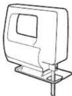
natural_image
Line drawing of a kitchen air conditioner unit with no text or symbols on the diagram itself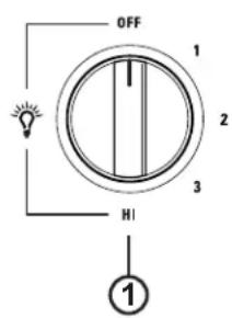
text_image
OFF 1 2 3 HI ①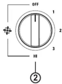
text_image
OFF 1 2 3 HI ②For your Safety
Before servicing or cleaning unit, switch power off at service panel and lock the service disconnecting means to prevent power from being switched on accidentally. When the service disconnecting means cannot be locked, securely fasten a prominent warning device, such as a tag, to the service panel.
Baffle Grease Filters and Drip Trays (on some models)
Some models have reusable metal grease baffles and drip trays.
The metal baffles channel grease released by foods on the cooktop into the drip trays. The baffles also help prevent flaming foods on the cooktop from damaging the inside of the hood.
For this reason, the baffles must ALWAYS be in place when the hood is used. The grease baffles and drip trays should be cleaned once a month, or as needed.
To clean the grease baffles and drip trays, drain and wipe all excess grease with a dry paper towel. Soak them and then swish them around in hot water and detergent. Don't use ammonia or ammonia products because they will darken the metal. Do not use abrasives or oven cleaners. Rinse, shake and let them dry before replacing. They may also be cleaned in an automatic dishwasher.
To remove:
Grasp the baffle knobs and pull them up, forward and out. Grasp the drip tray and carefully lift it up and out of the hood track.
To replace the drip trays:
- Place and seat the drip tray into the hood track.
- Slide them left or right until all trays are side-by-side in place in the track.
To replace the baffles:
- Hold the baffle at the bottom by one of the knobs.
- Place the other end of the baffle against the inside front of the hood.
- Slide it up and push the bottom end back until it firmly seats into place.
To clean behind the knobs:
If the knobs are difficult to remove, place a non-abrasive cloth between the knob gap and hood body to assist with pulling the knobs off for cleaning.

text_image
Drip Tray Track Drip Tray
natural_image
Line drawing of a hand holding a rectangular object on a surface, with no text or symbols present.Drip Tray Replacement

text_image
Baffle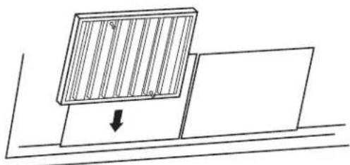
natural_image
Simple line drawing of a panel being lowered into a flat surface, with no text or symbols present.Baffle Replacement
Stainless Steel Surfaces (on some models)
Do not use a steel wool pad; it will scratch the surface.
To clean the stainless steel surface, use warm sudsy water or a stainless steel cleaner or polish. Always wipe the surface in the direction of the grain. Follow the cleaner instructions for cleaning the stainless steel surface.
To inquire about purchasing stainless steel appliance cleaner or polish, or to find the location of a dealer nearest you, please call our toll-free number:
National Parts Center 1.800.626.2002
GEApplianceParts.com
Light Bulbs
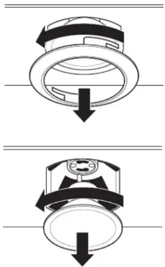
To change the light bulbs:
- Grasp the outer trim ring and twist until reaching the unlock position. Then pull the ring straight out.
- Grasp the bulb and twist until reaching the unlock position. Then gently pull the bulb straight out.
- Replace with the same wattage, type and size bulb. Wear gloves. Do not touch bulb with your bare fingers.
These 120 volt, 50 watt halogen bulbs with a GU10 base are available at specialty lighting stores and home building centers.
Order bulb no. WB08X10052.
4. Replace the outer trim ring by inserting the two retaining tabs into the two tab slots, pressing the ring flush with the surface of the hood insert and twisting until reaching the lock position.
natural_image
Two identical diagrams showing a mechanical component with downward arrows, no text or symbols present.Installation Instructions
Professional Vent Hood
? "If you have questions, call GE Appliances at 800.GE.CARES (800.432.2737) or visit our website at: GEAppliances.com"
BEFORE YOU BEGIN
Read these instructions completely and carefully.
- IMPORTANT — Save these instructions for local inspector's use.
■ IMPORTANT — Observe all governing codes and ordinances.
■ Note to Installer – Be sure to leave these instructions with the Consumer.
■ Note to Consumer – Keep these instructions for future reference.
■ Skill level – Installation of this vent hood requires basic mechanical and electrical skills.
■ Completion time – Approximately 1 to 3 hours
■ Proper installation is the responsibility of the installer.
■ Product failure due to improper installation is not covered under the Warranty.
CAUTION
Due to the weight and size of
these vent hoods and to reduce the risk of personal injury or damage to the product, TWO PEOPLE ARE REQUIRED FOR PROPER INSTALLATION.
FOR YOUR SAFETY
WARNING
Before beginning the installation,
switch power off at service panel and lock the service disconnecting means to prevent power from being switched on accidentally. When the service disconnecting means cannot be locked, securely fasten a prominent warning device, such as a tag, to the service panel.
WARNING
TO REDUCE THE RISK OF FIRE,
ELECTRIC SHOCK OR INJURY TO PERSONS, OBSERVE THE FOLLOWING:
A. Installation work and electrical wiring must be done by qualified person(s) in accordance with all applicable codes and standards, including fire-rated construction.
B. Sufficient air is needed for proper combustion and exhausting of gases through the flue (chimney) of fuel burning equipment to prevent back drafting. Follow the heating equipment manufacturer's guidelines and safety standards such as those published by the National Fire Protection Association (NFPA), the American Society for Heating, Refrigeration and Air Conditioning Engineers (ASHRAE) and the local code authorities.
C. When cutting or drilling into wall or ceiling, do not damage electrical wiring and other hidden utilities.
D. Ducted fans must always be vented to the outdoors.
E. Turn off breaker to adjacent rooms while working.
WARNING
TO REDUCE THE RISK OF FIRE,
USE ONLY METAL DUCT WORK.
WARNING
Disconnect all electrical power
at the main circuit breaker or fuse box before installing.
Installation Preparation
PRODUCT DIMENSIONS
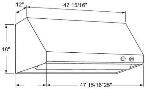
text_image
12" 47 15/16" 18" 47 15/16"25"Model CV48S With Straight Sides
HARDWARE PACKAGE
Locate and check contents.
2 (3/16") hollow wall anchors with screws to secure hood to the wall at the bottom

2 flat washers for wall anchors

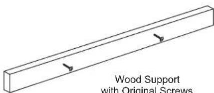
6 Phillips head screws to secure hood to the wood support: (2 secured to wood support)
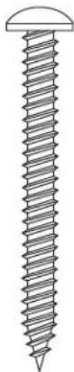
6 screws to secure the wood support and the hood to the wall
PARTS PROVIDED
Locate the parts packed with the hood.

2 Knobs
natural_image
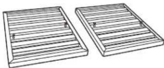
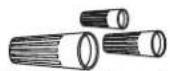
Two identical 3D-rendered wooden slatted or vent vats with horizontal grooves and small protrusions (no text or symbols)2 Stainless Steel Grease Filters (3 filters with 48" models)
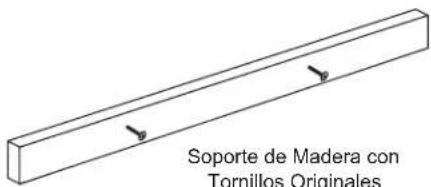
text_image
Wood Support with Original Screws
natural_image
Pure line drawing of two abstract geometric shapes with no text or symbols2 Grease Filter Trays (3 supports with 48" models.)
Installation Preparation
TOOLS AND MATERIALS REQUIRED
(NOT SUPPLIED)
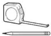
Pencil and tape measure
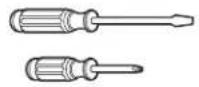
Phillips and Flat blade screwdrivers

Duct tape
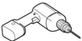
Electric drill with 1/8" and 3/8" bits

1/4" pivoting hex socket

Spirit level

Safety glasses

Flashlight
UL Listed Wire nuts

Pliers

Hammer
Wire Cutter/Stripper

Tin Snips
natural_image
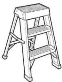
Line drawing of a four-tiered ladder structure (no text or symbols)Ladder

Saber saw or Key Hole Saw
120V 60Hz. 15 or 20 Amp, 2-wire with ground. Properly grounded branch circuit.
10" round metal duct, length to suit installation

Strain relief for junction cover.
CAUTION
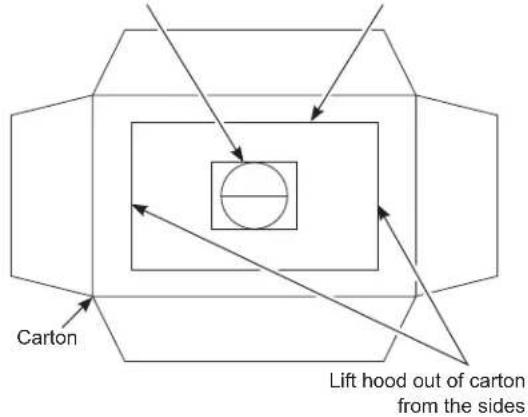
Lift the hood by grasping the
outside edges of the inlet opening of the hood. Do not lift the hood by grasping the exhaust opening or transition duct with damper!
■ Open the carton and remove the hood and packaging.
■ Confirm that all hardware and parts are present by reviewing the section named Parts Provided in the Installation Instructions.
■ Loosen the screws holding the wood support to the back of the hood. Remove wood support. Keep wood support and screws. These will be used to mount the hood to the wall.
■ Fully inspect and confirm that all tape and packing material has been removed from the hood and transition duct with damper
Do not lift from
transition duct Hood
text_image
Carton Lift hood out of carton from the sidesTop view of open shipping carton
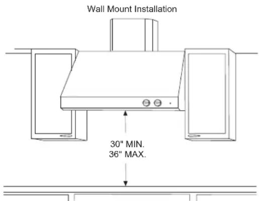
INSTALLATION CLEARANCES
These vent hoods are designed to be installed onto a wall or beneath a soffit or cabinet.
■ Install these hoods 30" Min. to 36" Max. above the cooking surface.
NOTE: Clearances may vary due to type of cooking product and local codes. Check with local inspectors to be sure standard is applicable.

text_image
Soffit Installation SOFFIT 30" MIN. 36" MAX.In this installation the ductwork running from the top of the hood will be concealed in the soffit or upper cabinetry.
text_image
Wall Mount Installation 30" MIN. 36" MAX.For this installation, a decorative duct cover is available to conceal the ductwork running from the top of the hood. Use of the duct cover requires special consideration to the installation height above the countertop.
OPTIONAL DUCT COVER ACCESSORIES
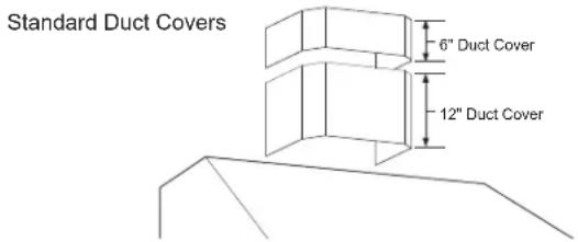
Standard decorative duct covers are available in 6" and 12" heights. Duct covers may be stacked, in various combinations, to conceal the ductwork running from the top of the hood to the ceiling.
■ Before you begin, you should determine the installation height of the hood and order the correct size duct cover. The duct covers should be ordered at the same time as the vent hood and be on site before installation. Order the duct cover corresponding to your model.
text_image
Standard Duct Covers 6" Duct Cover 12" Duct Cover6" Duct Covers
| Hood Model | 6” Duct Cover Dimensions | |
| CV48S UX | 48DC6J 6"H x 19-1 | 1/16"W x 11-7/8"D |
12" Duct Covers
| Hood Model | 12” Duct Cover Dimensions | |
| CV48S UX | 48DC12J 12"H x 19-11/16"W x 11-7/8"D | |
OPTIONAL SERVICE PART RANGE HOOD UTENSIL HOLDER
A utensil rack part # WB02X25909 is available as a service part for this hood.
Visit GEApplianceParts.com for more details.
DETERMINE INSTALLATION HEIGHT, DUCT COVER ACCESSORIES
These vent hoods must be installed 30" min. to 36" max. above the standard 36" high cooking surface when installed over any professional style rangetop or range. The exact hood installation height is determined by the ceiling height.
- Measure the exact ceiling height.
- Review the chart at right to determine the range of possible hood installation heights that can be accomplished with one or more duct covers.
- Increase or decrease hood installation height to accommodate the fixed 6" or 12" duct covers and use a whole number of duct covers, otherwise cutting and modifying one duct cover may be required.
- Duct covers may be stacked, in various combinations, to reach ceiling heights.
Straight or Taper-Sided Hoods

text_image
Duct Covers Ceiling Height to Floor 18" Hood Height Installation HeightNOTE: Minimum ceiling height for REAR WALL EXHAUST with duct covers is 8'4" when installing at 30" above countertop using 10" elbow.
| Actual Ceiling Height | *Possible Hood Installation Height | 6" Duct Covers | 12" Duct Covers |
| 7' 11" 35" 1 | |||
| 8' 0" | 30" | 1 | |
| 8' 0" | 36" 1 | ||
| 8' 1" 31" 1 | |||
| 8' 2" 32" 1 | |||
| 8' 4" 33" 1 | |||
| 8' 4" 34" 1 | |||
| 8' 5" 35" 1 | |||
| 8' 6" | 30" | 1 | 1 |
| 8' 6" | 36" | 1 | |
| 8' 7" 31" 1 | 1 | ||
| 8' 8" 32" 1 | 1 | ||
| 8' 9" 33" 1 | 1 | ||
| 8' 10" 34" 1 | 1 | ||
| 8' 11" 35" 1 | 1 | ||
| 9' 0" | 30" | 2 | |
| 9' 0" | 36" 1 | 1 | |
| 9' 1" 31" 2 | |||
| 9' 2" 32" 2 | |||
| 9' 3" 33" 2 | |||
| 9' 4" 34" 2 | |||
| 9' 5" 35" 2 | |||
| 9' 6" | 30" | 2 | |
| 9' 6" | 36" 1 | 1 | |
| 9' 7" 31" 1 | 2 | ||
| 9' 8" 32" 1 | 2 | ||
| 9' 9" 33" 1 | 2 | ||
| 9' 10" 34" 1 | 2 | ||
| 9' 11" 35" 1 | 2 | ||
| 10' 0" | 30" | 3 | |
| 10' 0" | 36" 1 | 2 | |
| 10' 1" 31" 3 | |||
| 10' 2" 32" 3 | |||
| 10' 3" 33" 3 | |||
| 10' 4" 34" 3 |
*Based on 36" countertop height.
NOTE: Additional duct covers may be used to reach higher ceilings.
ADVANCE PLANNING
Duct Install Planning
These vent hoods are equipped for 10" round ductwork. For best performance, use 10" round ductwork on the 48" wide hoods.
This hood may be vented vertically through upper cabinets, soffit or ceiling. A duct transition piece is supplied for vertical exhaust. Use locally supplied elbows to vent horizontally through the rear wall.
■ Use metal ductwork only.
■ Determine the exact location of the vent hood.
■ Plan the route for venting exhaust to the outdoors. To maximize the ventilation performance of the vent system:
-
Minimize the duct run length and number of transitions and elbows.
-
Maintain a constant duct size.
-
Seal all joints with duct tape to prevent any leaks.
-
Do not use any type of flexible ducting.
■ Use the shortest and straightest duct route possible.
■ Install a wall cap or roof cap with damper at the exterior opening. Order the wall or roof cap and any transition needed in advance.
■ When applicable, install any makeup (replacement) air system in accordance with local building code requirements. Visit GEAppliances.com for available makeup air solutions.
Wall Framing for Adequate Support
■ This vent hood is heavy. Adequate structural support must be provided. The hood must be secured to vertical studs in the wall. See page 14.
■ We strongly recommend that the vent hood with duct cover be on site before final framing and wall finishing. This will also help to accurately locate the ductwork and electrical service.
Decorative Duct Covers:
Decorative duct covers, 6" and 12" high, are available to fit all models. The duct cover conceals the ductwork running from the top of the hood to the ceiling or soffit. Stack one or more duct covers over the top of the hood to reach your ceiling height.
POWER SUPPLY
IMPORTANT – (Please read carefully)
WARNING
FOR PERSONAL SAFETY, THIS APPLIANCE MUST BE PROPERLY GROUNDED.
Remove house fuse or open circuit breaker before beginning installation.
Do not use an extension cord or adapter plug with this appliance. Follow National Electrical Codes or prevailing local codes and ordinances.
Electrical supply
These vent hoods must be supplied with 120V, 60Hz, and connected to an individual, properly grounded branch circuit, and protected by a 15 or 20 amp circuit breaker or time delay fuse.
■ Wiring must be 2 wire with ground.
If the electrical supply does not meet the above requirements, call a licensed electrician before proceeding.
■ Route house wiring as close to the installation location as possible in the ceiling or wall.
■ Connect the wiring to the house wiring in accordance with local codes.
Grounding instructions
The grounding conductor must be connected to a ground metal, permanent wiring system, or an equipment-grounding terminal or lead on the hood.
WARNING
The improper connection of the
equipment-grounding conductor can result in a risk of electric shock. Check with a qualified electrician or service representative if you are in doubt whether the appliance is properly grounded.
1 DETERMINE HOOD, DUCTWORK AND WIRING LOCATIONS
■ Use a level to draw the cooktop centerline location. Draw the line to ceiling height.
■ Measure desired distance from the bottom of the hood to the cooking surface, 30" min. to 36" max.
NOTE: If you are installing the hood with duct covers, be sure to read "Using Duct Cover Accessories" page 7. Exact installation height may be determined by use of one or more duct covers.
■ Use a level to draw a straight horizontal pencil line indicating the bottom of the hood.
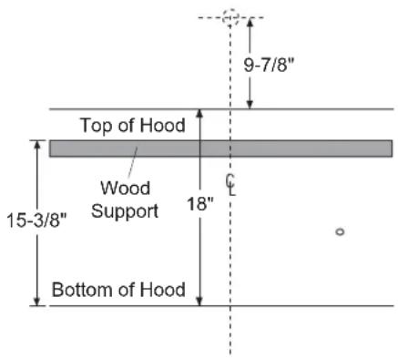
■ From the line indicating the bottom of the hood, measure 15-3/8" up and draw another line for the location of the wood support. See illustration.
FOR VERTICAL (Straight Up) DUCTING:
■ Use a level to draw a centerline from the bottom of the hood to ceiling or soffit.
■ If venting out the ceiling, extend the centerline forward on the ceiling or soffit.
- Locate the centerline of a 10-1/2" hole on the ceiling or soffit by measuring 6" from the wall.
text_image
9-7/8" Top of Hood Wood Support 15-3/8" Bottom of Hood 18"FOR DUCTING THROUGH REAR WALL:
■ Measure 9-7/8" above the marked line for the top of the hood. At the centerline, mark location for a 10-1/2" diameter hole.
NOTE: Minimun ceiling height for REAR WALL EXHAUST with duct covers is 8'4" when installing at 30" above countertop using 10" elbow
House Wiring Location:
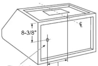
■ The junction box is fastened to the back of the hood on the right side.
text_image
8-3/8" ØElectrical
Area
18-13/16" for 48" Models
12-13/16" for 36" Models
9-13/16" for 30" Models
■ The recessed back side of the hood provides a large area for the house wiring to exit the wall and be routed to the rear knockout and junction box.
■ Remove junction box cover and knockout. Install strain relief.

text_image
18-1/16" for 48" Models 12-1/16" for 36" Models 9-1/16" for 30" Models 6-1/2"Alternate Knockout Locations
If the installation requires, the junction box can be relocated from the back to the top of the hood. Remove 3 screws, align box to top knockout and secure with original screws.
■ Remove junction box cover and knockout. Install strain relief.
2A INSTALL HOOD ONTO WALL
SKIP THIS STEP IF INSTALLING BENEATH A SOFFIT OR CABINET, GO TO STEP 2B.
- Locate at least 2 vertical studs at the wood support.
For 30" models, if 2 vertical studs cannot be located, then install 2 screws through the wood support into the stud that is located, vertically aligned with the screws located 12 " from the edge of the wood support.
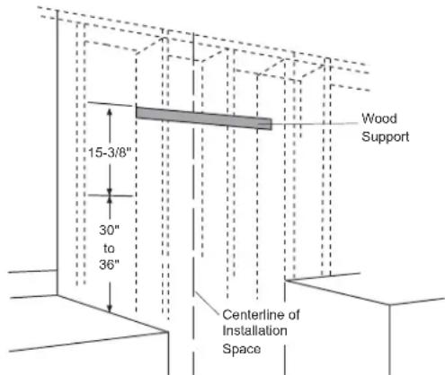
■ Center the supplied wood support, left to right and below the 15-3/8" marked line.
text_image
15-3/8" 30" to 36" Wood Support Centerline of Installation Space- Secure the wood support to 2 or more vertical studs, using at least 2 of the 4 supplied long screws. For the 30" model, you may need to add framing to existing framing to secure the wood support to 2 studs.
IMPORTANT: Screws must penetrate at least 1" into vertical studs. Countersink screws into support.
NOTE: The mounting screws must remain in their original shipping location. These screws are positioned to engage the keyhole slots in the back of the hood.
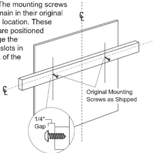
text_image
The mounting screws main in their original location. These are positioned ge the slots in of the Original Mounting Screws as Shipped 1/4" Gap■ Adjust depth of original mounting screws in the wood support until they protrude 1/4" forward. This 1/4" gap will provide clearance to hang the hood.
IMPORTANT: Framing must be capable of supporting up to 150 lbs.
■ Use duct tape to seal the transition duct connection. Check to be sure the damper moves freely.
Hang Hood On Wood Support
■ Lift the hood and hold close to the installation location. Route house wiring through the knockout and into the junction box.
■ Place the hood over the wood support. Be sure the mounting screws engage the keyhole slots in the back of the hood. Tighten the screws.

text_image
30" to 36" Centerline of Installation Space■ Install additional 4 screws to secure the hood to the wood support.
- Drill 1/8" pilot holes into the two lower holes. If the pilot hole enters a stud, use a washer and the long wood screw. If the pilot hole does not enter a stud, enlarge the hole to 3/8" to accept the wall anchor, and use a washer and the screw from the wall anchor.
2B Alternate Mounting Method INSTALL HOOD TO SOFFIT OR BENEATH CABINETS
SKIP THIS STEP IF USING WALL MOUNTING METHOD
When necessary, the hood may be installed so that it is supported by the soffit.
■ The soffit should be constructed with 2 x 4's.
■ Determine the installation location on the wall.
■ Continue the centerline forward on the bottom of the cabinet or soffit.
■ The opening above the hood should allow for the 10" round duct and clearance to slide the hood back against the wall.
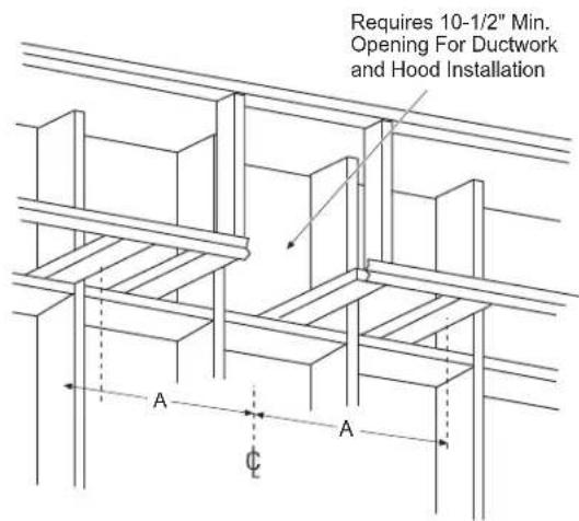
text_image
Requires 10-1/2" Min. Opening For Ductwork and Hood Installation A C A■ The 2 x 4 studs must be located as shown in the chart, Dim. A. to accept mounting screws.
| “A” Centerline to Stud and Keyhole Slots | “B” Hood Width At the Top | |
| CV48S 23- | 9/16" 47-15/16" |

text_image
2" A Top View Front of Hood 7-1/2" 10" 2-9/16" B 3/4" Back of Hood- Drill 1/8" pilot holes into the studs at the locations shown in the top view illustration.
IMPORTANT: Soffit framing must be capable of supporting up to 150 lbs.
■ Use duct tape to seal the transition duct connection. Check to be sure the damper moves freely.
Mount Hood onto Soffit or Cabinet
NOTE: If mounting to the underside of a cabinet with a recessed bottom, install shims to fill the gap.

text_image
Cabinet or Soffit Engage Top Keyhole Slots 1/4" Gap Add Shims If Bottom Is Recessed Push Back to Wall Back Wall■ Drive mounting screws into the studs until they protrude 1/4". The 1/4" gap will provide clearance to engage the keyhole slots in the top of the hood.
■ Lift hood to installation position. Locate house wiring and route through the knockout (from the back or top of the hood).
■ Lift hood onto mounting screws. Slide back against the rear wall.
■ Tighten mounting screws.
IMPORTANT: For additional support and to minimize vibration during operation, the hood must be secured to the back wall. Use wall anchors to fasten bottom back of hood to the wall.
3 CONNECT DUCTWORK
■ Install ductwork, making connections in direction of airflow as illustrated.
■ Secure joints in ductwork with sheetmetal screws.
■ Wrap all duct joints with duct tape for an airtight seal.
■ Use duct tape to seal the flange connection. Reach inside the hood and push the damper up to be sure it moves freely.

text_image
Duct Tape Over Seam and Screw Air Flow Screw Duct Tape Over Transition5 INSTALL DUCT COVERS
NOTE: For easier handling, remove cardboard insert after film is peeled off.
Remove protective film from duct covers. If more than one duct cover is used, secure each piece together with screws provided.
■ Place the duct cover(s) on top of the hood.
■ From inside the hood, secure the duct cover to the top with the small Phillips head screws supplied with the covers.
4 CONNECT ELECTRICAL
Verify that power is turned off at the source.
WARNING
WARNING If house wiring is not 2-wire with a ground wire, a ground must be provided by the installer. When house wiring is aluminum, be sure to use U.L. approved anti-oxidant compound and aluminum-to-copper connectors.
A
Remove
Junction Box
Cover
B. Insert Power Conduit Thru Strain Relief and Tighten
C. Use UL Listed Wire Nuts

text_image
White Black■ Use wire nuts to connect incoming ground to green, white to white and black to black.
■ Push wires into junction box and replace cover. Be sure wires are not pinched.
6 INSTALL FILTERS

natural_image
Line drawing of a hand holding a rectangular object on a surface (no text or symbols)■ Place filter drip trays into the rear of the hood.

natural_image
Simple line drawing of a grid structure with an arrow indicating downward motion (no text or symbols)■ Insert the grease filter into the opening and drop into the trays.
■ To remove the filters, grasp the handle, push the filter up and lift out.
Troubleshooting tips ... Before you call for service
Save time and money! Review the charts on the following pages first and you may not need to call for service.
| Problem Possible Cause | |
| Fan and lights do not operate when the switches are turned on | ■ The hood was never electrically connected by the installer/ electrician/builder. Call the electrician/installer/builder to complete the installation. This is not covered by warranty.■ A fuse may be blown or a circuit breaker tripped. Replace the fuse or reset the circuit breaker. |
| The blower does not work but the lights do | ■ The blower motor wire harness was not connected or was not connected properly by the installer/electrician/builder to its mating connector located inside the hood on the top surface, to the left of the blower assembly.1. Switch power off at service panel and lock the service disconnecting means to prevent power from being switched on accidentally. When the service disconnecting means cannot be locked, securely fasten a prominent warning device, such as a tag, to the service panel.2. Remove the filters and locate the blower wire harness connector. Is it plugged into its mating connector?3. If no, plug the blower motor connector into its mating connector on the top of the hood. Switch the power back on. Check to see if the fan now works.4. If no, check the circuit breaker/fuse. If it is blown/tripped, replace/reset it. Does the blower work now? If no, call GE Appliances for service. |
| The blower fails to exhaust the smoke/ steam/ odors adequately | ■ Many factors could be the root cause for reduced air-flow.1. Installation could be the problem: Your hood was designed to meet specific ducting requirements. If your duct length exceeds the manufacturer's requirements, hood performance will suffer. Air-flow will also be reduced if the house duct work is too small or there are too many elbows in the system. Contact your installer or builder.2. Obstruction in duct work could be the problem: Make sure nothing is blocking the vent (bird nests or kinks in the duct work).3. Damper blade may not be opening: Make sure the tape is removed from the damper blades and that it swings open freely.4. Damper blade on Wall or Roof Cap may not be opening: Contact your builder so they can make sure the damper swings open freely.5. Dirty filters/baffles: Make sure filters (and all hood surfaces) are kept clean of grease and dirt.6. Check to be sure the filter is clean: If replacing the filter does not correct the problem, call for service.7. Sufficient makeup (replacement) air is required for exhausting appliances to operate to rating. Check with local building codes, which may require or strongly advise the use of makeup air. Visit GEAppliances.com for available makeup air solutions. |
Troubleshooting tips ... Before you call for service
| Problem Possible Cause | |
| The halogen does not work | ■ The lamp or socket may be defective or a wire could be disconnected.1. Do some trouble-shooting by removing the lamp and place it in the socket of a lamp that does work. Does it work now? If no, the lamp is defective. If your hood is still in-warranty, call GE Appliances service and ask them to mail out a new lamp. Lamps on this product are covered by warranty and are cataloged. If the hood is no longer covered by warranty, reference the Care and Cleaning section of this manual to see lamp requirements. Lamps can be purchased at home building stores, specialty lighting stores or through GE Appliances Parts. Reference the defective lamp for information as well.2. If you placed the lamp in a working socket and it does illuminate, the original socket may be defective or a wire may be disconnected. Call GE Appliances for service. |
| Part is missing/damaged/defective | ■ In the unlikely event that a part would be missing, damaged or defective, we can serve you, the consumer, quickly by mailing these parts to you. We have identified several easy-to-install parts.These include:Lamps, lamp bezels, filters, baffles, grease trays, knobs, Owner's Manual and Installation Instructions.Call GE Appliances service and carefully describe your model number and the part you need.The model number is located inside the hood chassis, behind the filter/baffle. |
| Duct cover is missing | ■ The duct cover is not included with the hood. It must be purchased as an accessory.- 6" duct cover for use with a 48" hood-order kit #UX48DC6J- 12" duct cover that works with a 48" hood-order kit #UX48DC12JCall GE Appliances Parts. See Consumer Service page in this manual for a list of phone numbers. |
| Installation part is missing/damaged/defective | We provide a 10" round, vertical duct transition. This part can be mailed out to the hood installer if it is in some way unusable. All other duct transitions, elbows, etc must be purchased locally. We can also mail out many other parts that come with the hood to your installer. Call GE Appliances Service. See Consumer Service page in this manual for a list of phone numbers. Ask them to mail the parts only-no service call required. |
GE Appliances Vented Range Hood Warranty
GEAppliances.com
All warranty service is provided by our Factory Service Centers, or an authorized Customer Care® technician. To schedule service online, visit us at www.geappliances.com/service_and_support/, or call GE Appliances at 800.GE.CARES (800.432.2737). Please have your serial number and your model number available when calling for service.
Servicing your appliance may require the use of the onboard data port for diagnostics. This gives a GE Appliances factory service technician the ability to quickly diagnose any issues with your appliance and helps GE Appliances improve its products by providing GE Appliances with information on your appliance. If you do not want your appliance data to be sent to GE Appliances, please advise your technician not to submit the data to GE Appliances at the time of service.
| For the period of GE Appliances will replace | |
| One yearFrom the dateof the originalpurchase | Any part of the cooking product which fails due to a defect in materials or workmanship.During this limited one-year warranty, GE Appliances will provide, free of charge, all laborand related service costs to replace the defective part. |
What GE Appliances will not cover:
■ Service trips to your home to teach you how to use the product.
■ Improper installation, delivery, or maintenance.
■ Failure of the product if it is abused, misused, modified, or used for other than the intended purpose or used commercially.
■ Replacement of house fuses or resetting of circuit breakers.
■ Damage to the product caused by accident, fire, floods, or acts of God.
■ Damage to finish, such as surface rust, tarnish, or small blemishes not reported within 48 hours of delivery.
■ Incidental or consequential damage caused by possible defects with this appliance.
■ Damage caused after delivery.
■ Product not accessible to provide required service.
■ Service to repair or replace light bulbs, except for LED lamps.
EXCLUSION OF IMPLIED WARRANTIES
Your sole and exclusive remedy is product repair as provided in this Limited Warranty. Any implied warranties, including the implied warranties of merchantability or fitness for a particular purpose, are limited to one year or the shortest period allowed by law.
This warranty is extended to the original purchaser and any succeeding owner for products purchased for home use within the USA. If the product is located in an area where service by a GE Appliances Authorized Servicer is not available, you may be responsible for a trip charge or you may be required to bring the product to an Authorized GE Appliances Service location for service. In Alaska, the warranty excludes the cost of shipping or service calls to your home. Some states do not allow the exclusion or limitation of incidental or consequential damages. This warranty gives you specific legal rights, and you may also have other rights which vary from state to state. To know what your legal rights are, consult your local or state consumer affairs office or your state's Attorney General.
Warrantor: GE Appliances, a Haier company
Extended Warranties: Purchase a GE Appliances extended warranty and learn about special discounts that are available while your warranty is still in effect. You can purchase it online anytime at
www.geappliances.com/service_and_support/shop-for-extended-service-plans.htm
or call 800.626.2224 during normal business hours. GE Appliances Service will still be there after your warranty expires.
Looking For Something More?
GE Appliances offers a variety of accessories to improve your cooking and maintenance experiences!
Refer to the Consumer Support page for phone numbers and website information.
The following products and more are available:
Parts
| Baffle |
| Drip Tray |
Accessories
| Halogen Lamp |
Cleaning Supplies
| CitruShineTM Stainless Steel Wipes |
| CERAMA BRYTEStainless Steel Appliance Cleaner |
Consumer Support
GE Appliances Website
Have a question or need assistance with your appliance? Try the GE Appliances Website 24 hours a day, any day of the year! You can also shop for more great GE Appliances products and take advantage of all our on-line support services designed for your convenience. In the US: GEAppliances.com
Register Your Appliance
Register your new appliance on-line at your convenience! Timely product registration will allow for enhanced communication and prompt service under the terms of your warranty, should the need arise. You may also mail in the pre-printed registration card included in the packing material. In the US: GEAppliances.com/register
Schedule Service
Expert GE Appliances repair service is only one step away from your door. Get on-line and schedule your service at your convenience any day of the year. In the US: GEAppliances.com/ge/service-and-support/service.htm or call 800.432.2737 during normal business hours.
Extended Warranties
Purchase a GE Appliances extended warranty and learn about special discounts that are available while your warranty is still in effect. You can purchase it on-line anytime. GE Appliances Services will still be there after your warranty expires. In the US: GEAppliances.com/ge/service-and-support/shop-for-extended-service-plans.htm or call 800.626.2224 during normal business hours.
Remote Connectivity
For assistance with wireless network connectivity (for models with remote enable), visit our website at GEAppliances.com/ge/connected-appliances/ or call 800.220.6899 in the US.
Parts and Accessories
Individuals qualified to service their own appliances can have parts or accessories sent directly to their homes (VISA, MasterCard and Discover cards are accepted). Order on-line today 24 hours every day. In the US: GEApplianceparts.com or by phone at 877.959.8688 during normal business hours.
Instructions contained in this manual cover procedures to be performed by any user. Other servicing generally should be referred to qualified service personnel. Caution must be exercised, since improper servicing may cause unsafe operation.
Contact Us
If you are not satisfied with the service you receive from GE Appliances, contact us on our Website with all the details including your phone number, or write to:
In the US: General Manager, Customer Relations | GE Appliances, Appliance Park | Louisville, KY 40225 GEAppliances.com/ge/service-and-support/contact.htm
natural_image
Line drawing of a 3D kitchen appliance with a sloped top and two circular buttons at the base (no text or symbols)natural_image
Line drawing of a hand holding a rectangular object on a surface, with no text or symbols present.natural_image
Simple line drawing of a mechanical component with a downward arrow indicating motion (no text or symbols)natural_image
Two mechanical component diagrams showing downward force application (no text or symbols)DIMENSIONES DEL PRODUCTO

text_image
12" 47 15/16" 18" 47 15/16"25"natural_image
Two identical 3D wireframe diagrams of wooden slatted panels with internal slots (no text or symbols)2 Filtros de Grasa de Acero Inoxidable (3 filtros en modelos de 48")
natural_image
Pure line drawing of two symmetrical 3D geometric shapes with no text or symbolsnatural_image
Line drawing of a wooden double staircase with no text or symbolsEscalera
natural_image
Line drawing of a hand holding a rectangular object on a line, with no text or symbols present.natural_image
Simple line drawing of a grid structure with an arrow indicating downward motion (no text or symbols)www.geappliances.com/service\_and\_support/shop-for-extended-service-plans.htm
En EE.UU.: General Manager, Customer Relations | GE Appliances, Appliance Park | Louisville, KY 40225 GEAppliances.com/ge/service-and-support/contact.htm