
UATYQ600MCY17 - Air Conditioning DAIKIN - Free user manual and instructions
Find the device manual for free UATYQ600MCY17 DAIKIN in PDF.

User questions about UATYQ600MCY17 DAIKIN
0 question about this device. Answer the ones you know or ask your own.
Ask a new question about this device
Download the instructions for your Air Conditioning in PDF format for free! Find your manual UATYQ600MCY17 - DAIKIN and take your electronic device back in hand. On this page are published all the documents necessary for the use of your device. UATYQ600MCY17 by DAIKIN.
USER MANUAL UATYQ600MCY17 DAIKIN
Operating Manual Wired Remote Controller
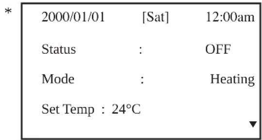
- Upon power up of the unit, the LCD displays the main display screen
text_image
* 2000/01/01 [Sat] 12:00am Status : OFF Mode : Heating Set Temp : 24°C ▼- Press the ON/OFF button for 1 second to switch on the unit if the status shows OFF. The status will change to ON. The ON/OFF LED will light up.
- Press the COOL button for 1 second if cooling is required or the HEAT button if heating is required.
- The 'Set Temp' refers to temperature setting.
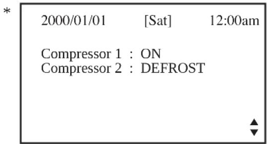
- Press the ▼ button once to view the compressor(s) on, off or defrost status.
text_image
* 2000/01/01 [Sat] 12:00am Compressor 1 : ON Compressor 2 : DEFROST- Press the ▼ button again to view the temperature for room and outdoor ambient.

text_image
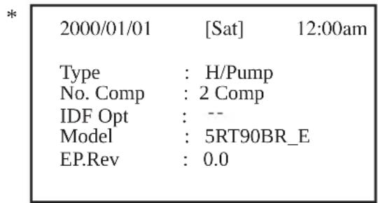
* 2000/01/01 [Sat] 12:00am Return Air : 24.0°C Outdoor Air : 24.0°C- Press the ▼ button again to view the selected type for unit, number of compressor used, indoor fan ‘always on’ option, model and EEPROM version.
text_image
* 2000/01/01 [Sat] 12:00am Type : H/Pump No. Comp : 2 Comp IDF Opt : -- Model : 5RT90BR_E EP.Rev : 0.0- Press the ▲ button to return to previous screen(s) or ESC to return to main screen.
- Press the ALARM button to view or clear the alarm history. If alarm occurs, contact your dealer or serviceman.
* Note: Display diagram is for illustration purpose only. It may differ for different models. The display information shall be subjected to the setting in the main controller board.
B. Main Menu
- Changes can be made to the factory setting parameter. This is done in the Main Menu. Press ENTER button to go into the Main Menu.
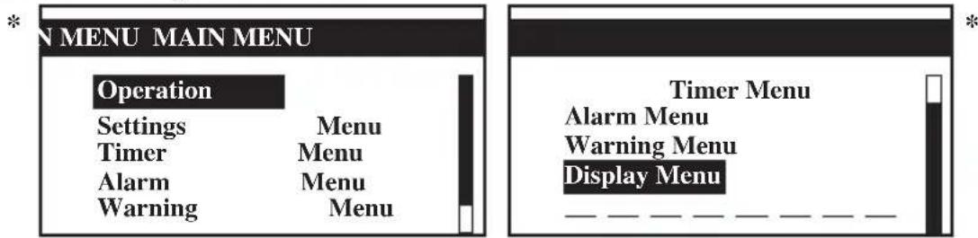
- The Main Menu consists of Operation Menu, Settings Menu, Timer Menu, Alarm Menu, Warning Menu and Display Menu.
How to use the Main Menu?
Step 1
Press ENTER to view the sub-Menu under Main Menu.
Step 2
Go to the sub-Menu you want by pressing the ▲ or ▼ button. Press ENTER to select the sub-Menu.
Step 3
Go to the parameter you want to change or view by pressing the ▲ or ▼ button. Press ENTER to select this parameter.
Step 4
Change the parameter by pressing the ▲ or ▼ button. Once completed press ENTER. Press ESC to go back to previous screen until you see the initial display screen.
Operation Menu
This menu enables us to set the unit status (on or off), set the unit operation mode, change the temperature setting, and manually defrost the unit (applicable for heating mode only).
Settings Menu
This menu enables us to set the parameters for unit operation (requires password entering), user setting, change password, set panel option and unlock panel.
The panel option enables us to set the LCD backlight and contrast, set the alarm buzzer, enable and disable the screen saver and set a screen saver timeout and set the temperature display in °C or °F.
Note: The Set Parameter in the setting menu requires password for any changes to or to view its parameter.
CAUTION:
All the password entering must be done by local dealer/serviceman. User is not allowed to change the value of the set parameter as this may cause damage to unit or deter its operation.
Timer Menu
This menu enables us to set the clock, set the date, set a 7 days schedule to start and stop the unit and enable or disable the set schedule.
Alarm Menu
This menu enables us to view the alarm history and also clear the record. The panel can keep up to 20 fault / alarm records.
Warning Menu
This menu enables us to view the warning history and also to clear the record. The panel can keep up to 20 warning records.
Display Menu
This menu enables us to view the indoor heat exchanger sensor(s) temperature, outdoor heat exchanger sensor(s) temperature, discharge sensor(s) temperature, solenoid valve(s) operation status, compressor(s) run time record, EXV opening pulse, economizer operation status (applicable for unit with economizer only), filter checking time, control type and software version. Some of the submenu may require password for entering.
Main Menu
Press ENTER to go to this menu.
text_image
N MENU MAIN MENU Operation Settings Menu Timer Menu Alarm Menu Warning Menu Timer Menu Alarm Menu Warning Menu Display Menu __________________There are 6 sub menus in [Main Menu]. Press ▲ or ▼ to select sub menus, ENTER to enter into the sub menu or press ESC to exit to main display screen.
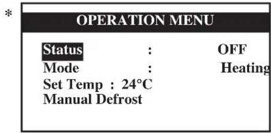
Operation Menu
Select [Operation Menu] in [Main Menu] and press ENTER to go to this menu.
text_image
OPERATION MENU Status : OFF Mode : Heating Set Temp : 24°C Manual DefrostSome basic settings can be done here. Press ▲ or ▼ to select the required setting. Then, press ENTER to enter the setting mode. Press ▲ or ▼ to toggle the setting. Press ENTER again to confirm the setting. Press ESC to exit to [Main Menu].
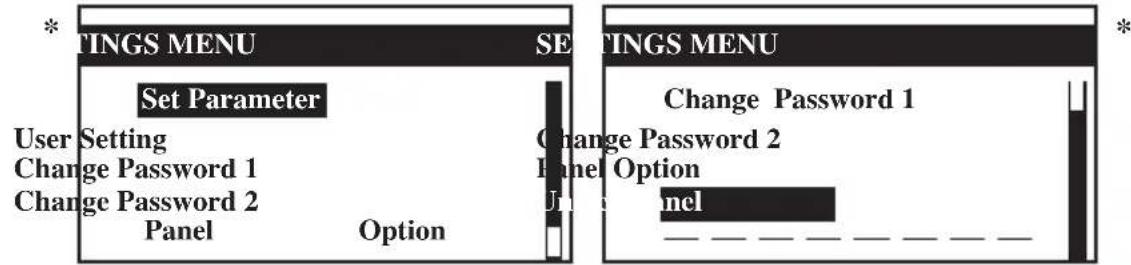
Settings Menu
Select [Settings Menu] in [Main Menu] and press ENTER to go to this menu.
text_image
TINGS MENU Set Parameter User Setting Change Password 1 Change Password 2 Panel Option TINGS MENU Change Password 1 Change Password 2 Panel Option Panel _____________________________Some advance settings can be found here. Press ▲ or ▼ to select the required setting. Then, press ENTER to enter the setting mode. Press ▲ or ▼ to toggle the setting. Press ENTER again to confirm the setting. Press ESC to exit to [Main Menu].
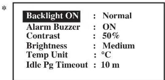
Panel Option
Select [Panel Option] in [Settings Menu] and press ENTER to go to this menu.
text_image
Backlight ON : Normal Alarm Buzzer : ON Contrast : 50% Brightness : Medium Temp Unit : °C Idle Pg Timeout : 10 mPress ▲ or ▼ to select the required setting, ENTER to enter into the setting.
Press ▲ or ▼ to select the required option, ENTER to select the option.
Press ESC to exit to [Settings Menu].
* Note: Display diagram is for illustration purpose only. It may differ for different models. The display information shall be subjected to the setting in the main controller board.
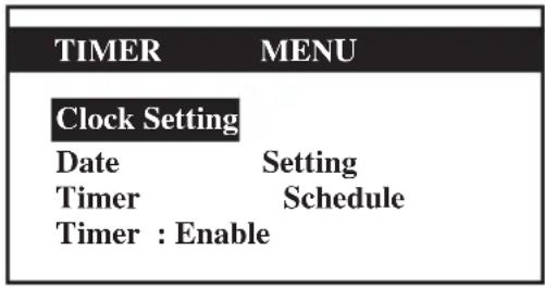
Timer Menu
Select [Timer Menu] in [Main Menu] and press ENTER to go to this menu.
*
text_image
TIMER MENU Clock Setting Date Setting Timer Schedule Timer : EnableAll the timer/schedule settings are included in this menu. Press ▲ or ▼ to select the required setting. Then, press ENTER to enter the setting mode. Press ▲ or ▼ to toggle the setting. Press ENTER again to confirm the setting. Press ESC to exit to [Main Menu].
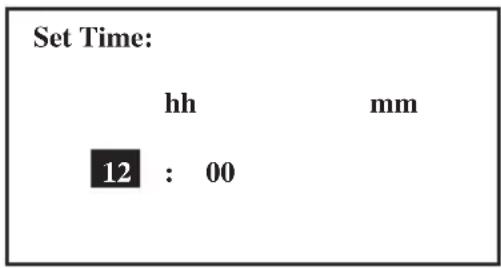
Clock Setting
Select [Clock Setting] in [Timer Menu] and press ENTER to go to this menu.
*
text_image
Set Time: hh mm 12 : 00Press ▲ or ▼ to select the required option. Then, press ENTER to enter the setting mode. Press ▲ or ▼ to toggle the setting. Press ENTER again to confirm the setting. Press ESC to exit to [Timer Menu].
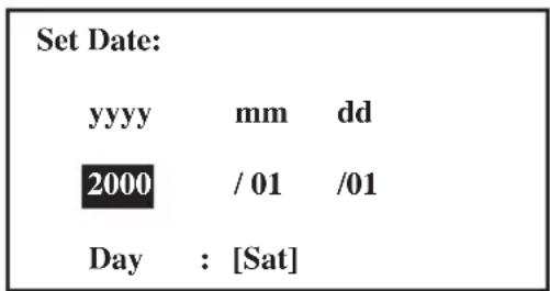
Date Setting
Select [Date Setting] in [Timer Menu] and press ENTER to go to this menu.
*
text_image
Set Date: yyyy mm dd 2000 / 01 /01 Day : [Sat]Press ▲ or ▼ to select the required option, ENTER to select the option.
Press ESC to exit to [Timer Menu].
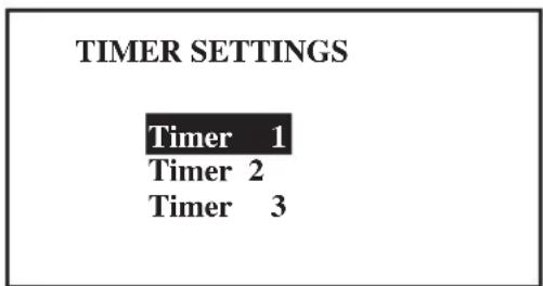
Timer Schedule
Select [Timer Schedule] in [Timer Menu] and press ENTER to go to this menu.
*
text_image
TIMER SETTINGS Timer 1 Timer 2 Timer 3| TIMER 1 ON OFF | ||
| Sun | 0800 1800 | |
| Mon | 0800 1800 | |
| Tue | 0800 1800 | |
| Wed | 0800 1800 |
This is the 7 days programmable timer schedule menu. There are 3 ON/OFF events in one day. User can choose to set each day (Sunday - Saturday) ON/OFF timer.
Before this schedule can function, user needs to set the [Timer] in [Timer Menu] to enable.
Press ESC to exit to [Timer Menu].
* Note: Display diagram is for illustration purpose only. It may differ for different models.
The display information shall be subjected to the setting in the main controller board.
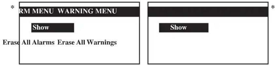
Alarm Menu/Warning Menu
Select [Alarm Menu]/[Warning Menu] in [Main Menu] and press ENTER to go to this menu.
text_image
* RM MENU WARNING MENU Show Erase All Alarms Erase All Warnings * ShowThis place keeps records for all previous occurred faults/alarms/warnings.
User can view or clear these records. The panel can keep up to 20 faults/alarm warning records.
Press ESC to exit to [Main Menu].
Show Alarms/Show Warnings
Select [Show Alarms]/[Show Warnings] in [Main Menu] and press ENTER to go to this menu.
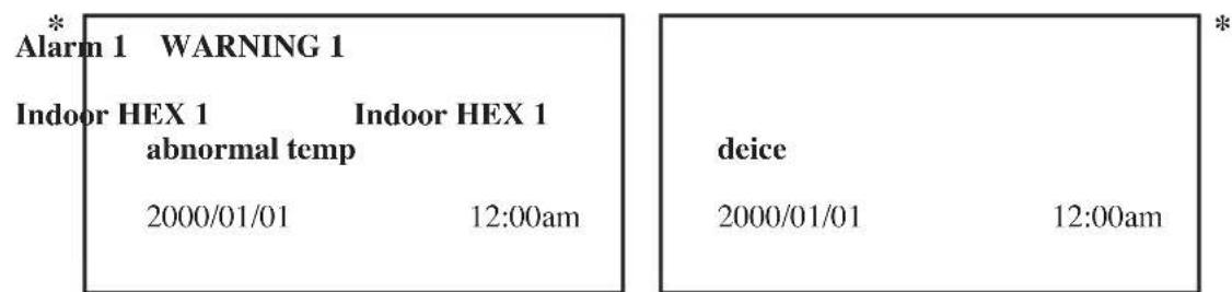
text_image
* Alarm 1 WARNING 1 Indoor HEX 1 Indoor HEX 1 abnormal temp 2000/01/01 12:00am deice 2000/01/01 12:00amThe record shows: - Alarm/Warning description
- Alarm/Warning occurrence date
- Alarm/Warning occurrence time
Besides that, user can erase the alarm/warning record(s) in this menu (password is required).
Press ESC to exit to [Alarm Menu]/[Warning Menu].
Display Menu
Select [Display Menu] in [Main Menu] and press ENTER to go to this menu.
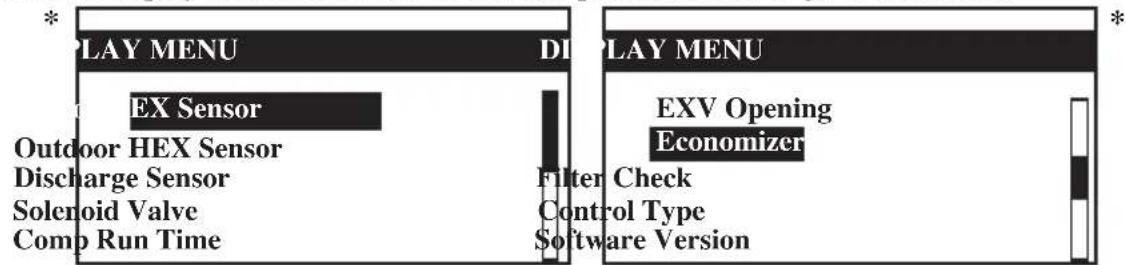
text_image
PLAY MENU EX Sensor Outdoor HEX Sensor Discharge Sensor Solenoid Valve Comp Run Time DI Filter Check Control Type Software Version PLAY MENU EXV Opening EconomizerThis menu displays indoor heat exchanger sensor(s) temperature, outdoor heat exchanger sensor(s) temperature, discharge sensor(s) temperature, solenoid valve(s) operation status, compressor(s) run time record, EXV opening pulse, economizer operation status (applicable for unit with economizer only), filter checking time, control type and software version. Some of the submenu may require password for entering. Besides that, user can clear the compressor run time record (password is required).
Press ESC to exit to [Main Menu].
* Note: Display diagram is for illustration purpose only. It may differ for different models. The display information shall be subjected to the setting in the main controller board.
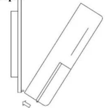
C. Installation
When installing the LCD panel to the bracket,
Step 1 Step 2
natural_image
Pure technical line drawing of a mechanical component or bracket without any text, numbers, or symbolsHook the LCD panel
from the bottom first
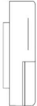
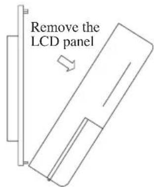
When removing the LCD panel from the bracket,
Step 1 Step 2
Remove the LCD panel from the top part first
natural_image
Pure geometric line drawing of a 3D rectangular prism without any text, numbers, or symbols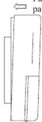
natural_image
Simple line drawing of a rectangular object with an arrow pointing to it, no text or symbols present.Push to fasten the LCD panel to the bracket
text_image
Remove the LCD panel-
A 3V DC battery is supplied with the LCD. It is used to ensure that the LCD displays real time once the timer is set.
-
The LCD is wired to the main board via CN8 connection.
| Alarm 1 WARNING 1 | |
| Indoor HEX 1 Indoor HEX 1 abnormal temp | |
| 2000/01/01 12:00am | |
| deice | |
| 2000/01/01 12:00am | |
natural_image
Pure technical line drawing of a mechanical component or bracket (no text or symbols)natural_image
Simple line drawing of a rectangular object with two vertical lines and a horizontal bar, no text or symbols present.natural_image
Pure geometric line drawing of a rectangular shape with no text, numbers, or symbols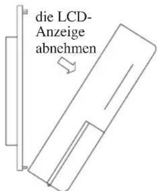
| * Alarm 1 | WARNING 1 | * | |
| Indoor HEX 1 | Indoor HEX 1 | deice | |
| abnormal temp | |||
| 2000/01/01 | 12:00am | 2000/01/01 | 12:00am |
natural_image
Pure technical line drawing of a mechanical component or bracket (no text or symbols)natural_image
Pure geometric line drawing of a rectangular shape with no text, numbers, or symbols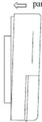
text_image
par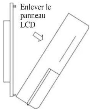
text_image
Enlever le panneau LCDtext_image
Alarm 1 Indoor HEX 1 abnormal temp 2000/01/01 12:00am WARNING 1 Indoor HEX 1 deice 2000/01/01 12:00amnatural_image
Pure technical line drawing of a mechanical component or bracket without any text, numbers, or symbolsnatural_image
Simple line drawing of a rectangular object with an arrow labeled 'va' pointing to it (no text or symbols beyond the label)natural_image
Pure geometric line drawing of a vertical rectangle with internal lines, no text or symbols present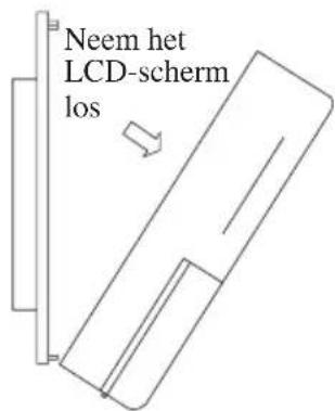
text_image
* Alarm 1 WARNING 1 Indoor HEX 1 Indoor HEX 1 abnormal temp 2000/01/01 12:00am deice 2000/01/01 12:00amtext_image
Alarm 1 Indoor HEX 1 abnormal temp 2000/01/01 12:00am WARNING 1 Indoor HEX 1 deice 2000/01/01 12:00amnatural_image
Pure technical line drawing of a mechanical component or bracket (no text or symbols)natural_image
Pure geometric line drawing of a vertical rectangle with internal lines, no text or symbols present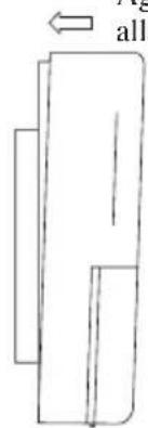
natural_image
Simple line drawing of a rectangular object with an arrow pointing to it, no text or symbols present.| * | Alarm 1 | WARNING | * 1 | ||
| Indoor HEX 1 abnormal temp | Indoor HEX 1 | deice | |||
| 2000/01/01 | 12:00am | 2000/01/01 | 12:00am | ||
natural_image
Pure technical line drawing of a mechanical component without any text, numbers, or symbolsnatural_image
Pure geometric line drawing of a rectangular shape with no text, numbers, or symbols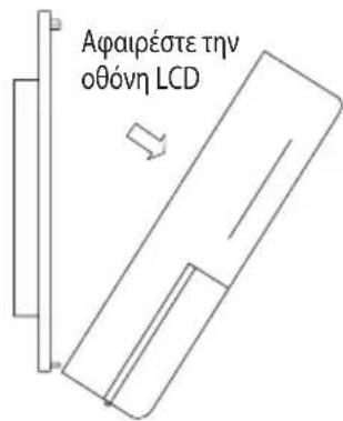
| * Alarm 1 WARNING 1 Indoor HEX 1 Indoor HEX 1 abnormal temp 2000/01/01 12:00am | deice | |
| 2000/01/01 | 12:00am | |
natural_image
Pure technical line drawing of a mechanical component or bracket (no text or symbols)natural_image
Simple line drawing of a rectangular object with internal lines, no text or symbols present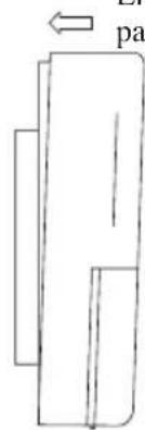
text_image
patext_image
Remover o painel LCDnatural_image
Simple diagram with a black rectangle and a horizontal bar, no text or symbols presenttext_image
* Alarm 1 WARNING 1 Indoor HEX 1 Indoor HEX 1 abnormal temp 2000/01/01 12:00am| deice | |
| 2000/01/01 | 12:00am |
natural_image
Pure geometric line drawing of a rectangular shape with no text, numbers, or symbols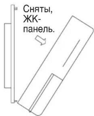
| Alarm 1 | WARNING 1 | * | |
| Indoor HEX 1 abnormal temp | Indoor HEX 1 deice | ||
| 2000/01/01 | 12:00am | 2000/01/01 | 12:00am |
natural_image
Pure technical line drawing of a mechanical component or bracket (no text or symbols)natural_image
Simple line drawing of a rectangular object with internal lines, no text or symbols presentnatural_image
Simple line drawing of a rectangular object with internal lines, no text or symbols present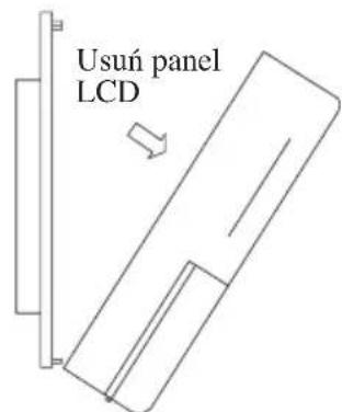
text_image
Usuń panel LCD| * Alarm 1 WARNING 1 Indoor HEX 1 Indoor HEX 1 abnormal temp 2000/01/01 12:00am | deice 2000/01/01 12:00am |
Disposal Requirements

The batteries supplied with the controller are marked with this symbol.
This means that the batteries shall not be mixed with unsorted household waste.
If a chemical symbol is printed beneath the symbol, this chemical symbol means that the batteries contains a heavy metal above a certain concentration.
Possible chemical symbols are:
■ Pb: lead (>0.004%)
■ Hg: mercury (>0.0005%)
Waste batteries must be treated at a specialized treatment facility for re-use. By ensuring correct disposal, you will help to prevent potential negative consequences for the environment and human health. Please contact your local authority for more information.
Batterie
P.O.Box 18674, Galleries 4, 11th Floor, Downtown Jebel Ali, Dubai, UAE.
Importer for Turkey
DAIKIN ISITMA ve SOĞUTMA SISTEMLERI SAN TIC A.Ş.
JR Shinagawa East Bldg., 2-18-1, Konan,
Minato-ku, Tokyo, 108-0075 Japan
http://www.daikin.com/global/
P.O.Box 18674, Galleries 4, 11th Floor,
Downtown Jebel Ali, Dubai, UAE.
Importer for Turkey
DAIKIN ISITMA ve SOĞUTMA SISTEMLERI SAN TIC A.Ş.
natural_image
Pure technical line drawing of a mechanical component without any text, numbers, or symbolsnatural_image
Simple line drawing of a rectangular object with two vertical rectangles and a horizontal line inside (no text or symbols)text_image
SETTINGS MENU Change Password 1 Change Password 2 Panel Option Unlock Panel2000/01/01 [Sat] 12:00am
Status : OFF
Mode : Heating
Set Temp : 24°C

2000/01/01 [Sat] 12:00am
Compressor 1 : ON
Compressor 2 : DEFROST

2000/01/01 [Sat] 12:00am
Return Air : 24.0°C
Outdoor Air : 24.0°C

2000/01/01 [Sat] 12:00am
Type : H/Pump
No. Comp : 2 Comp
IDF Opt : --
Model : 5RT90BR_E
EP.Rev : 0.0