GHPH-MM16 - Heat pump GRUNDIG - Free user manual and instructions
Find the device manual for free GHPH-MM16 GRUNDIG in PDF.

User questions about GHPH-MM16 GRUNDIG
0 question about this device. Answer the ones you know or ask your own.
Ask a new question about this device
Download the instructions for your Heat pump in PDF format for free! Find your manual GHPH-MM16 - GRUNDIG and take your electronic device back in hand. On this page are published all the documents necessary for the use of your device. GHPH-MM16 by GRUNDIG.
USER MANUAL GHPH-MM16 GRUNDIG
natural_image
Stylized stick figure with blue body and yellow head, no text or symbols present041
GHPH-MM08
GHPH-MM14
GHPH-MM10
GHPH-MM16
GHPH-MM12
EN - FR
CONTENTS
ENGLISH 3-135
FRANÇAIS 136-276
Advanced Important Notice
Cautions:
- Do not use means to accelerate the defrosting process or to clean, other than those recommended by the manufacturer.
- The appliance shall be stored in a room without continuously operating ignition sources (for example: open flames, an operating gas appliance or an operating electric heater.).
- Do not pierce or burn.
- Be aware that refrigerants may not contain an odour.
- Appliance shall be installed, operated and stored in a room with a floor area larger than X m ^2 (refer to specifications sheet).
- The installation of pipe-work shall be kept to a minimum X m2 (refer to specifications sheet).
- Spaces where refrigerant pipes shall be compliance with national gas regulations.
- Servicing shall be performed only as recommended by the manufacturer.
- The appliance shall be stored in a well-ventilated area where the room size corresponds to the room area as specified for operation.
- All working procedure that affets safety means shall only be carried by competent persons.
General Notice:
- Transport of equipment containing flammable refrigerants Compliance with the transport regulations
- Marking of equipment using signs Compliance with local regulations
-
Disposal of equipment using flammable refrigerants Compliance with national regulations
-
Storage of equipment/appliances The storage of equipment should be in accordance with the manufacturer's instructions.
-
Storage of packed (unsold) equipment Storage package protection should be constructed such that mechanical damage to the equipment inside the package will not cause a leak of the refrigerant charge. The maximum number of pieces of equipment permitted to be stored together will be determined by local regulations.
Please read this user manual first!
Dear Customer,
Thank you for preferring a Grundig product. We hope that you get the best results from your product which has been manufactured with high quality and state-of-the-art technology. Therefore, please read this entire user manual and all other accompanying documents carefully before using the product and keep it as a reference for future use. If you handover the product to someone else, give the user manual as well. Follow all warnings and information in the user manual.
Meanings of the symbols
Following symbols are used in the various section of this manual:

Important information or useful hints about usage.

Warning for hazardous situations with regard to life and property.

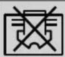
Warning to actions that must never perform.
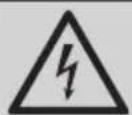
Warning for electric shock.

This symbol shows that information is available such as the operating manual or installation manual.
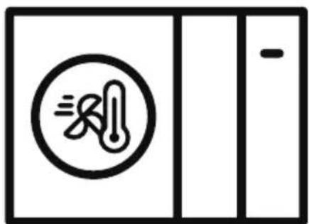
Do not cover it.

This symbol shows that the operation manual should be read carefully.
This symbol shows that a service personnel should be handling this equipment with reference to the installation manual.
(For R32/R290 gas type)
This symbol shows that this appliance used a flammable refrigerant. If the refrigerant is leaked and exposed to an external ignition source, there is a risk of fire.
CONTENTS
1 Safety precautions 8
2 General introduction 17
3 Accessories 21
3.1 Accessories supplied with the unit 21
3.2 Accessories from local supplier .....21
4 Before installation 22
5 Important information for the refrigerant 24
6 Installation site 25
6.1 Selecting a location in cold climates....27
6.2 Selecting a location in hot climates....27
7 Installation precautions 28
7.1 Dimensions 28
7.2 Installation requirements....29
7.3 Drain hole position 30
7.4 Servicing space requirements .....31
7.5 Reference: Recommended water circulation characteristics during installation. 33
8 Typical applications 34
8.1 Application 1....34
8.2 Application 2....36
8.3 Application 3.42
8.4 Balance tank volume requirement 47
9 Overview of the unit 48
9.1 Disassembling the unit....48
9.2 Main components....49
CONTENTS
9.3 Electronic control box....51
9.4 Water piping....64
9.5 Filling water 69
9.6 Water piping insulation....70
9.7 Field wiring 71
10 Start-up and configuration 87
10.1 DIP switch settings overview .....87
10.2 Initial start-up at low outdoor ambient temperature .....87
10.3 Pre-operation checks....88
10.4 The circulation pump .....89
10.5 Field settings 89
11 Test run and final checks 101
11.1 Final checks 101
12 Maintenance and service 102
13 Trouble shooting 104
13.1 General guidelines.... 104
13.2 General symptoms 104
13.3 Parameter view 106
13.4 Error codes.... 107
14 Technical specifications 116
14.1 General 116
14.2 Electrical specifications.... 117
14.3 General (3-Phase).... 117
14.4 Electrical specifications (3-Phase) 118
14.5 Energy rating label and Specification sheet.... 118
CONTENTS
15 Information servicing 123
16 European disposal guidelines 134
17 F-Gas instruction 135
1 Safety precautions

Warning:
- Before touching electric terminal parts, turn off power switch.
- When service panels are removed, live parts can be easily touched by accident.
- Never leave the unit unattended during installation or servicing when the service panel is removed.
- Do not touch water pipes during and immediately after operation as the pipes may be hot and could burn your hands. To avoid injury, give the piping time to return to normal temperature or be sure to wear protective gloves.
- Do not touch any switch with wet fingers. Touching a switch with wet fingers can cause electrical shock.
- Before touching electrical parts, turn off all applicable power to the unit.
- Tear apart and throw away plastic packaging bags so that children will not play with them. Children playing with plastic bags face danger of death by suffocation.
- Safely dispose of packing materials such as nails and other metal or wood parts that could cause injuries.

Warning:
- Ask your dealer or qualified personnel to perform installation work in accordance with this manual. Do not install the unit yourself. Improper installation could result in water leakage, electric shocks or fire.
- Be sure to use only specified accessories and parts for installation work. Failure to use specified parts may result in water leakage, electric shocks, fire, or the unit falling from its mount.
- Install the unit on a foundation that can withstand its weight. Insufficient physical strength may cause the equipment to fall and possible injury.
- Perform specified installation work with full consideration of strong wind, hurricanes, or earthquakes. Improper installation work may result in accidents due to equipment falling.
- Make certain that all electrical work is carried out by qualified personnel according to the local laws and regulations and this manual using a separate circuit. Insufficient capacity of the power supply circuit or improper electrical construction may lead to electric shocks or fire.
- Be sure to install a ground fault circuit interrupter according to local laws and regulations. Failure to install a ground fault circuit interrupter may cause electric shocks and fire.

Warning:
- Make sure all wiring is secure. Use the specified wires and ensure that terminal connections or wires are protected from water and other adverse external forces. Incomplete connection or affixing may cause a fire.
- When wiring the power supply, form the wires so that the front panel can be securely fastened. If the front panel is not in place there could be overheating of the terminals, electric shocks or fire.
- After completing the installation work, check to make sure that there is no refrigerant leakage.
- Never directly touch any leaking refrigerant as it could cause severe frostbite. Do not touch the refrigerant pipes during and immediately after operation as the refrigerant pipes may be hot or cold, depending on the condition of the refrigerant flowing through the refrigerant piping, compressor and other refrigerant cycle parts. Burns or frostbite are possible if you touch the refrigerant pipes. To avoid injury, give the pipes time to return to normal temperature or, if you must touch them, be sure to wear protective gloves.
- Do not touch the internal parts (pump, backup heater, etc.) during and immediately after operation. Touching the internal parts can cause burns. To avoid injury, give the internal parts time to return to normal temperature or, if you must touch them, be sure to wear protective gloves.

Warning:
- Ground the unit.
- Grounding resistance should be according to local laws and regulations.
- Do not connect the ground wire to gas or water pipes, lightning conductors or telephone ground wires.
-
Incomplete grounding may cause electric shocks.
-
Gas pipes: Fire or an explosion might occur if the gas leaks.
- Water pipes: Hard vinyl tubes are not effective grounds.
- Lightning conductors or telephone ground wires: Electrical threshold may rise abnormally if struck by a lightning bolt.
- Install the power wire at least 3 feet (1 meter) away from televisions or radios to prevent interference or noise. (Depending on the radio waves, a distance of 3 feet (1 meter) may not be sufficient to eliminate the noise.)
- Do not wash the unit. This may cause electric shocks or fire. The appliance must be installed in accordance with national wiring regulations. If the supply cord is damaged, it must be replaced by the manufacturer, its service agent or similarly qualified persons in order to avoid a hazard.

Warning:
- Do not install the unit in the following places:
- Where there is mist of mineral oil, oil spray or vapors. Plastic parts may deteriorate, and cause them to come loose or water to leak.
- Where corrosive gases (such as sulphurous acid gas) are produced. Where corrosion of copper pipes or soldered parts may cause refrigerant to leak.
- Where there is machinery which emits electromagnetic waves. Electromagnetic waves can disturb the control system and cause equipment malfunction.
- Where flammable gases may leak, where carbon fiber or ignitable dust is suspended in the air or where volatile flammables such as paint thinner or gasoline are handled. These types of gases might cause a fire.
- Where the air contains high levels of salt such as near the ocean.
- Where voltage fluctuates a lot, such as in factories.
- In vehicles or vessels.
- Where acidic or alkaline vapors are present.

Warning:
- This appliance can be used by children 8 years old and above and persons with reduced physical, sensory or mental capabilities or lack of experience and knowledge if they are supervised or given instruction on using the unit in a safe manner and understand the hazards involved. Children should not play with the unit. Cleaning and user maintenance should not be done by children without supervision.
- Children should be supervised to ensure that they do not play with the appliance.
- If the supply cord is damaged, it must be replaced by the manufacturer or its service agent or a similarly qualified person.
- DISPOSAL: Do not dispose this product as unsorted municipal waste. Collection of such waste separately for special treatment is necessary. Do not dispose of electrical appliances as municipal waste, use separate collection facilities. Contact your local government for information regarding the collection systems available. If electrical appliances are disposed of in landfills or dumps, hazardous substance can leak into the groundwater and get into the food chain, damaging your health and well-being.

Warning:
- The wiring must be performed by professional technicians in accordance with national wiring regulation and this circuit diagram. An all-pole disconnection device which has at least 3mm separation distance in all pole and a residual current device (RCD) with the rating not exceeding 30mA shall be incorporated in the fixed wiring according to the national rule.
- Confirm the safety of the installation area (walls, floors, etc.) without hidden dangers such as water, electricity, and gas. Before wiring/pipes.
- Before installation, check whether the user's power supply meets the electrical installation requirements of unit (including reliable grounding, leakage, and wire diameter electrical load, etc.). If the electrical installation requirements of the product are not met, the installation of the product is prohibited until the product is rectified.
- When installing multiple air conditioners in a centralized manner, please confirm the load balance of the three-phase power supply, and multiple units are prevented from being assembled into the same phase of the three-phase power supply.
1 Safety precautions

Warning:
- Product installation should be fixed firmly. Take reinforcement measures, when necessary.
- This appliance is intended to be used by expert or trained users in shops, in light industry and on farms, or for commercial use by lay persons"
- The A-weighted emission sound pressure level at workstations, where this exceeds 70 dB (A). If the A-weighted sound pressure level is below 70 dB, no value needs to be given, but the instructions shall state that the A-weighted sound pressure level is below 70 dB.
1 Safety precautions

Note:
- About Fluorinated Gasses
- This air-conditioning unit contains fluorinated gasses. For specific information on the type of gas and the amount, please refer to the relevant label on the unit itself. Compliance with national gas regulations shall be observed.
- Installation, service, maintenance and repair of this unit must be performed by a certified technician.
- Product uninstallation and recycling must be performed by a certified technician.
- If the system has a leak-detection system installed, it must be checked for leaks at least every 12 months. When the unit is checked for leaks, proper record-keeping of all checks is strongly recommended.
2 General introduction
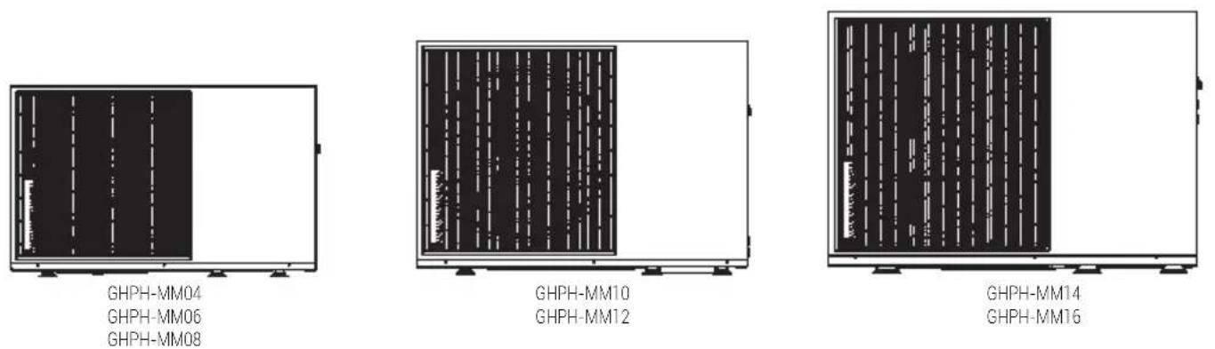
GHPH-MM04
GHPH-MM06
GHPH-MM08
GHPH-MM10
GHPH-MM12
GHPH-MM14
GHPH-MM16
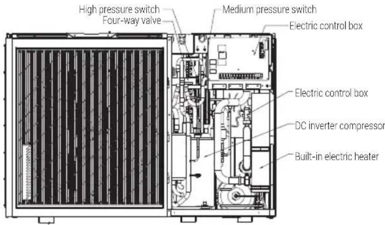
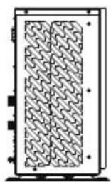
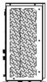
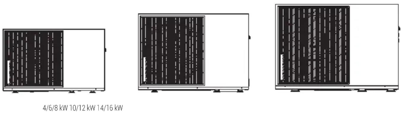
Internal layout: GHPH-MM14, GHPH-MM16 for example
natural_image
Pure electrical circuit lines without any symbols4/6/8 kW
natural_image
Pure mechanical component diagram with no text, numbers, or symbols10/12 kW
natural_image
Pure diagram of a rectangular frame with a patterned internal structure, no text or symbols present.14/16 kW

Note:
The picture and function described in this manual contain the backup heater components.
Pictures in this manual are for reference only, please refer to the actual product.
2 General introduction
| Unit | 1-phase 3-phase | ||||||||||
| 4 6 8 | 10 12 14 1 | 6 10 12 14 16 | |||||||||
| Capacity of backup heater | 3kW (1-phase)GHPH-MM04 GHPH-MM06 GHPH-MM08GHPH-MM10 GHPH-MM12 GHPH-MM14 GHPH-MM16 | 9kW (3-phase)GHPH-MM312GHPH-MM314GHPH-MM316 | |||||||||
• These units are used for both heating and cooling applications and domestic hot water tanks. They can be combined with fan coil units, floor heating applications, low temperature high efficiency radiators, domestic hot water tanks and solar kits, which are all field supplied.
• A wired controller is supplied with the unit.
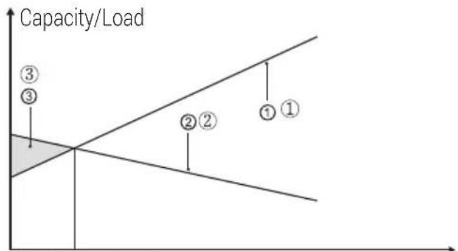
- If you choose the built-in backup heater unit, the backup heater can increase the heating capacity during cold outdoor temperature. The backup heater also serves as a backup in case of malfunctioning and for frozen protection of the outside water piping during winter time.
line
| Point | Capacity/Load | |---|---| | ① | High | | ② | Medium | | ③ | Low |Tbivalent Outdoor temperature
- Heat pump capacity.
- Required heating capacity (site dependent).
- Additional heating capacity provided by backup heater.
Domestic hot water tank (field supply)
A domestic hot water tank (with or without booster heater) can be connected to the unit.
The requirement of the tank is different for different unit and material of heat exchanger.
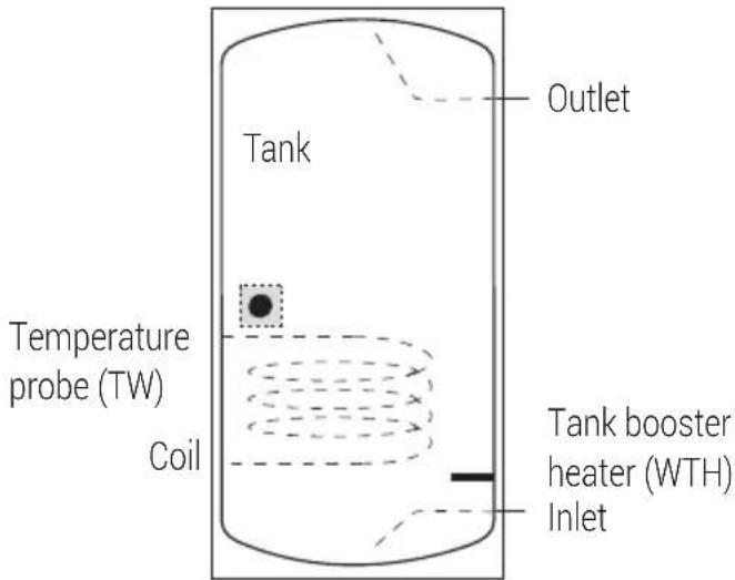
The booster heater should be installed below the temperature probe (TB).
The heat exchanger (coil) should be installed below the temperature probe.
The pipe length between the outdoor unit and tank should be less than 5 meters.
2 General introduction
| Model 4~6kW 8~10kW 12~16kW | ||||
| Volume of tank/L Recom | mended 100~250 | 150~300 200~500 | ||
| Heat exchange area/ m^2 (Stainless steel coil) | Minimum 1.4 1.4 1.6 | |||
| Heat exchange area/ m^2 (Enamel coil) | Minimum 2.0 2.0 2.5 | |||
Room thermostat (field supplied)
Room thermostat can be connected to the unit (room thermostat should be kept away from heating source when selecting the installation place).
Solar kit for domestic hot water tank (field supplied)
Operation range
| Outlet water (Heating mode) +1 | 2 ~ +65°C | |
| Outlet water (Cooling mode) +5 | ~ +25°C | |
| Domestic hot water +12 ~ +60°C | ||
| Ambient temperature 5 ~ +35°C | ||
| Water pressure 0.1~0.3MPa | ||
| Water flow | 4kW 10~20lt/minute | |
| 6kW 10~20lt/minute | ||
| 8kW 10~35lt/minute | ||
| 10kW | 10~35lt/minute | |
| 12kW | 10~50lt/minute | |
| 14kW | 10~50lt/minute | |
| 16kW | 10~50lt/minute | |
The unit have anti-freezing function that uses the heat pump or backup heater (Customized model) to keep the water system safe from freezing in all conditions. (Refer to 9.4 "Water piping").
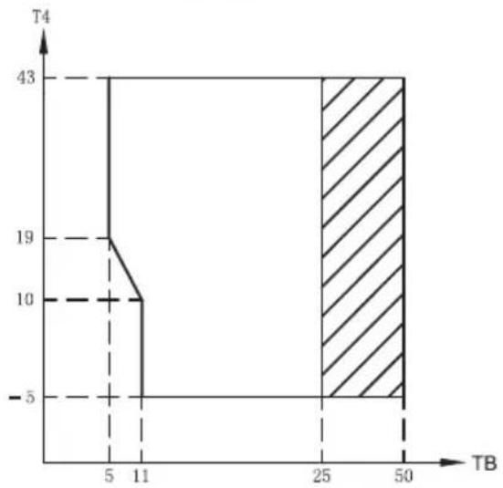
In cooling mode, the water flowing temperature (TB) range in different outdoor temperature (T4) is listed below:
line
| TB | T4 | | --- | --- | | 5 | 19 | | 11 | 10 | | 25 | 43 | | 50 | 43 |Operation range by heat pump with possible limitation and protection.
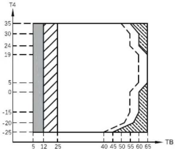
In heating mode, the water flowing temperature (TB) range in different outdoor temperature (T4) is listed below:
area
| TB | T4 | | --- | --- | | 5 | 35 | | 12 | 35 | | 25 | 35 | | 40 | -25 | | 45 | -20 | | 50 | -15 | | 55 | -10 | | 60 | -5 | | 65 | 0 |If IPH/AHS setting is valid, only IPH/AHS turns on; If IPH/AHS setting is invalid, only heat pump turns on, limitation and protection may
2 General introduction
occur during heat pump operation.
Operation range by heat pump with possible limitation and protection.
Heat pump turns off, only IPH/AHS turns on.
— — Maximum inlet water temperature line for heat pump operation.
In DHW mode, the water flowing temperature (TB) range in different outdoor temperature (T4) is listed below:
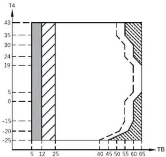
area
| TB | Value | | --- | ----- | | 5 | 43 | | 12 | 43 | | 25 | 43 | | 40 | -20 | | 45 | -20 | | 50 | -20 | | 55 | -20 | | 60 | -20 | | 65 | -20 |If IPH/AHS setting is valid, only IBH/AHS turns on; If IPH/AHS setting is invalid, only heat pump turns on, limitation and protection may occur during heat pump operation.
Operation range by heat pump with possible limitation and protection.
Heat pump turns off, only IPH/AHS turns on.
—— Maximum inlet water temperature line for heat pump operation.
3 Accessories
3.1 Accessories supplied with the unit
| Installation Fittings | ||
| Name Shape Quantity | ||
| Installation and owner's manual |  | 1 |
| Wired controller manual 1 |  | |
| Product fiche 1 |  | |
| Y-shape filter 1 |  | |
| Wired controller 1 |  | |
| 20m extension cord 1 |  | |
| Water outlet connection pipe assembly |  | 1 |
| Energy label 1 | 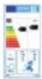 | |
| Shockproof 6 |  | |
| DHW sensor (8m) 1 |  | |
3.2 Accessories from local supplier
| Thermistor for balance tank (TE1) |  | 1 |
| Thermistor for Zone flow temp. (TZ2) |  | 1 |
| Thermistor for solar temp. (Tsolar) |  | 1 |
4 Before installation
- Before installation
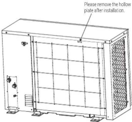
Be sure to confirm the model name and the serial number of the unit. - Handling
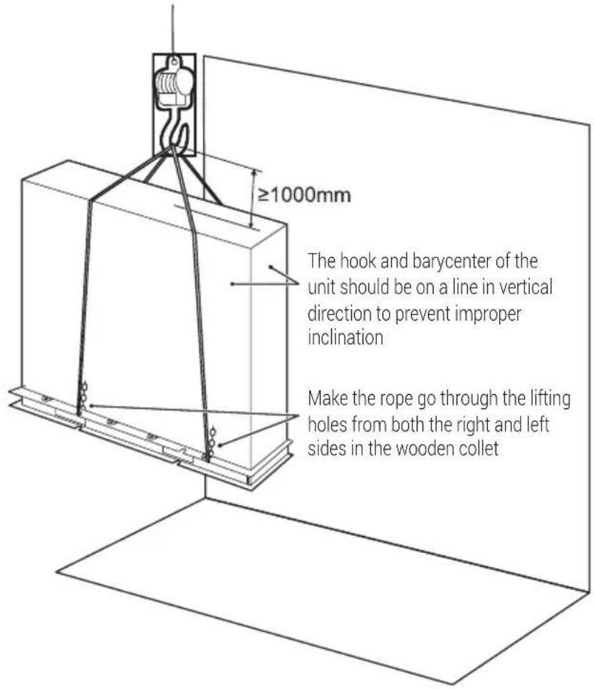
Due to relatively large dimensions and heavy weight, the unit should only be handled using lifting tools with slings. The slings can be fitted into foreseen sleeves at the base frame that are made specifically for this purpose.

Warning:
• To avoid injury, do not touch the air inlet or aluminum fins of the unit.
• Do not use the grips in the fan grills to avoid damage.
- The unit is top heavy! Prevent the unit from falling due to improper inclination during handling.
4 Before installation
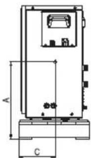
| Model A B C | |||
| 1 phase 4/6/8kW 470 | 460 220 | GHPH-MM04 | GHPH-MM06 GHPH-MM08 |
| 1 phase 10/12kW 450 | 440 230 | GHPH-MM10 | GHPH-MM12 |
| 1 phase 14/16kW 500 | 490 235 | GHPH-MM14 | GHPH-MM16 |
| 3 phase 12kW 450 | 440 230 G | GHPH-MM312 | |
| 3 phase 14/16kW 500 | 490 235 | GHPH-MM314, GHPH-MM316 | |
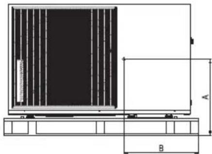
4/6/8 kW (unit: mm)
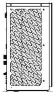
The position of barycenter for different units can be seen in the picture below.
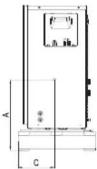
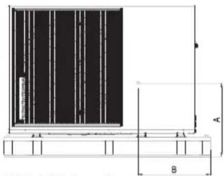
10/12 kW (unit: mm)
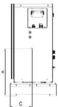
natural_image
Pure technical line drawing of a rectangular enclosure or enclosure with dimension labels A and C, no text or symbols present.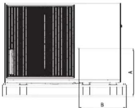
natural_image
Technical diagram showing a rectangular structure with vertical divisions and dimension labels A and B (no text or symbols beyond labels)14/16 kW (unit: mm)
5 Important information for the refrigerant
This product has the fluorinated gas, which is forbidden to release to air.
Refrigerant type: R32; Volume of GWP: 675.
GWP = Global Warming Potential
| Model | Factory charged refrigerant volume in the unit | |
| Refrigerant/kg Tonnes CO | _2 equivalent | |
| 4kW (1 Phase) 1.03 0.695 | ||
| 6kW (1 Phase) 1.03 0.695 | ||
| 8kW (1 Phase) 1.30 0.878 | ||
| 10kW (1 Phase) 1.50 1.013 | ||
| 12kW (1 Phase) 1.75 1.181 | ||
| 14kW (1 Phase) 2.10 1.417 | ||
| 16kW (1 Phase) 2.10 1.417 | ||
| 12kW (3 Phase) 1.75 1.181 | ||
| 14kW (3 Phase) 2.10 1.417 | ||
| 16kW (3 Phase) 2.10 1.417 | ||

Warning:
• Frequency of Refrigerant Leakage Checks
- For unit that contains fluorinated greenhouse gases in quantities of 5 tonnes of CO2 equivalent or more, but of less than 50 tonnes of CO2 equivalent, at least every 12 months, or where a leakage detection system is installed, at least every 24 months.
- For unit that contains fluorinated greenhouse gases in quantities of 50 tonnes of CO2 equivalent or more, but of less than 500 tonnes of CO2 equivalent at least every six months, or where a leakage detection system is installed, at least every 12 months.
- For unit that contains fluorinated greenhouse gases in quantities of 500 tonnes of CO_2 equivalent or more, at least every three months, or where a leakage detection system is installed, at least every six months.
- This air-conditioning unit is a hermetically sealed equipment that contains fluorinated greenhouse gases.
- Only certificated person is allowed to do installation, operation and maintenance.

Warning:
- There is flammable refrigerant in the unit and it should be installed in a well-ventilated site. If the unit is installed inside, an additional refrigerant detection device and ventilation equipment must be added in accordance with the standard EN378. Be sure to adopt adequate measures to prevent the unit from being used as a shelter by small animals.
- Small animals making contact with electrical parts can cause malfunction, smoke or fire. Please instruct the custom- er to keep the area around the unit clean.
- Select an installation site where the following conditions are satisfied and one that meets with your customer's approval.
- Places that are well-ventilated.
- Places where the unit does not disturb neighbors.
- Safe places which can bear the unit's weight and vibration and where the unit can be installed at an even level.
- Places where there is no possibility of flammable gas or product leak.
- The equipment is not intended for use in a potentially explosive atmosphere.
- Places where servicing space can be well ensured.
-
Places where the units' piping and wiring lengths come within the allowable ranges.
-
Places where water leaking from the unit cannot cause damage to the location (e.g. in case of a blocked drain pipe).
- Places where rain can be avoided as much as possible.
- Do not install the unit in places often used as a work space. In case of construction work (e.g. grinding etc.) where a lot of dust is created, the unit must be covered.
- Do not place any object or equipment on top of the unit (top plate).
- Do not climb, sit or stand on top of the unit.
- Be sure that sufficient precautions are taken in case of refrigerant leakage according to relevant local laws and regulations.
- Don't install the unit near the sea or where there is corrosion gas.
- When installing the unit in a place exposed to strong wind, pay special attention to the following.
Strong winds of 5 m/sec or more blowing against the unit's air outlet causes a short circuit (suction of discharge air), and this may have the following consequences:
- Deterioration of the operational capacity.
- Frequent frost acceleration in heating operation.
- Disruption of operation due to rise of high pressure.
- When a strong wind blows continuously on the front of the unit, the fan can start rotating very fast until it breaks.
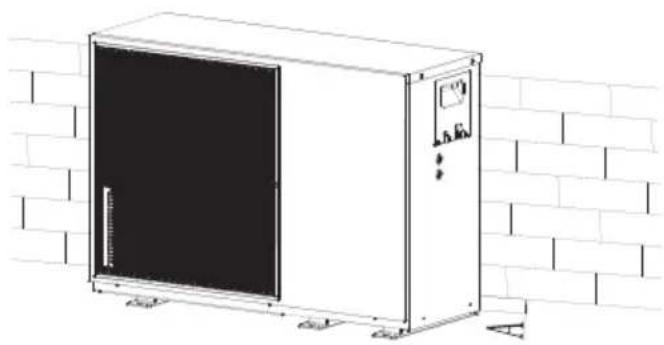
In normal condition, refer to the figures below for installation of the unit:
6 Installation site
natural_image
Line drawing of a white industrial enclosure with a black panel, mounted on a brick wall (no text or symbols)| Unit A (mm) | |
| 4~16kW ≥300 |
In case of strong wind and the wind direction can be foreseen, refer to the figures below for installation of the unit (any one is OK):
Turn the air outlet side toward the building's wall, fence or screen.
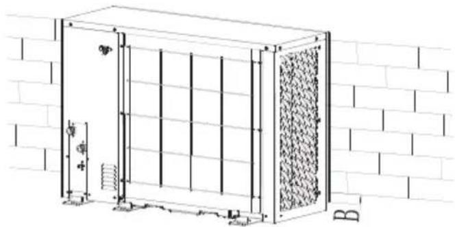
natural_image
Technical line drawing of a modular storage unit with vertical supports and a textured panel, set against a brick wall (no text or symbols)| Unit B (mm) | |
| 4~6kW ≥1000 | |
| 8~16kW ≥1500 |
Make sure there is enough room to do the installation. Set the outlet side at a right angle to the direction of the wind.
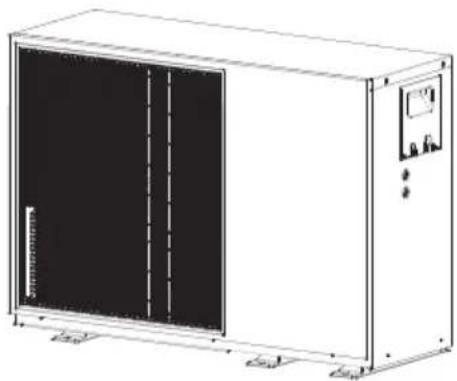
natural_image
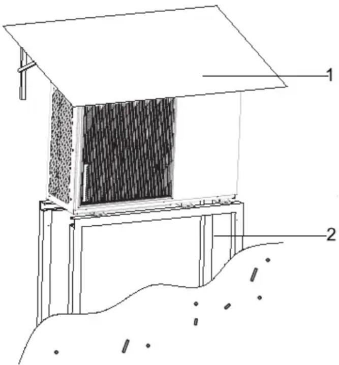
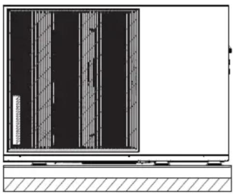
Line drawing of a rectangular industrial machine with a black panel and control panel (no text or symbols)• Prepare a water drainage channel around the foundation, to drain waste water from around the unit.
- If water does not easily drain from the unit, mount the unit on a foundation of concrete blocks, etc. (the height of the foundation should be about 100 mm (3.93 in).
- If you install the unit on a frame, please install a waterproof plate (about 100 mm) on the underside of the unit to prevent water from coming in from the low side.
- When installing the unit in a place frequently exposed to snow, pay special attention to elevate the foundation as high as possible.
- If you install the unit on a building frame, please install a waterproof tray (field supply) (about 100mm, on the underside of the unit) in order to avoid drain water dripping. (See the picture in the right).
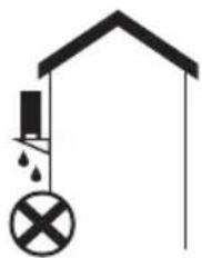
natural_image
Simple line drawing of a house with a hanging structure and a cross symbol (no text or labels)6 Installation site
6.1 Selecting a location in cold climates
Refer to "Handling" in section "4 Before installation"

Note:
When operating the unit in cold climates, be sure to follow the instructions described below.
- To prevent exposure to wind, install the unit with its suction side facing the wall.
- Never install the unit at a site where the suction side may be exposed directly to wind.
• To prevent exposure to wind, install a baffle plate on the air discharge side of the unit. - In heavy snowfall areas, it is very important to select an installation site where the snow will not affect the unit. If lateral snowfall is possible, make sure that the heat exchanger coil is not affected by the snow (if necessary construct a lateral canopy).
- Construct a large canopy.
- Construct a pedestal.
Install the unit high enough off the ground to prevent it from being buried in snow.
6.2 Selecting a location in hot climates
As the outdoor temperature is measured via the outdoor unit air thermistor, make sure to install the outdoor unit in the shade or a canopy should be constructed to avoid direct sunlight, so that it is not influenced by the sun's heat, otherwise protection may be possible to the unit.
7 Installation precautions
7.1 Dimensions
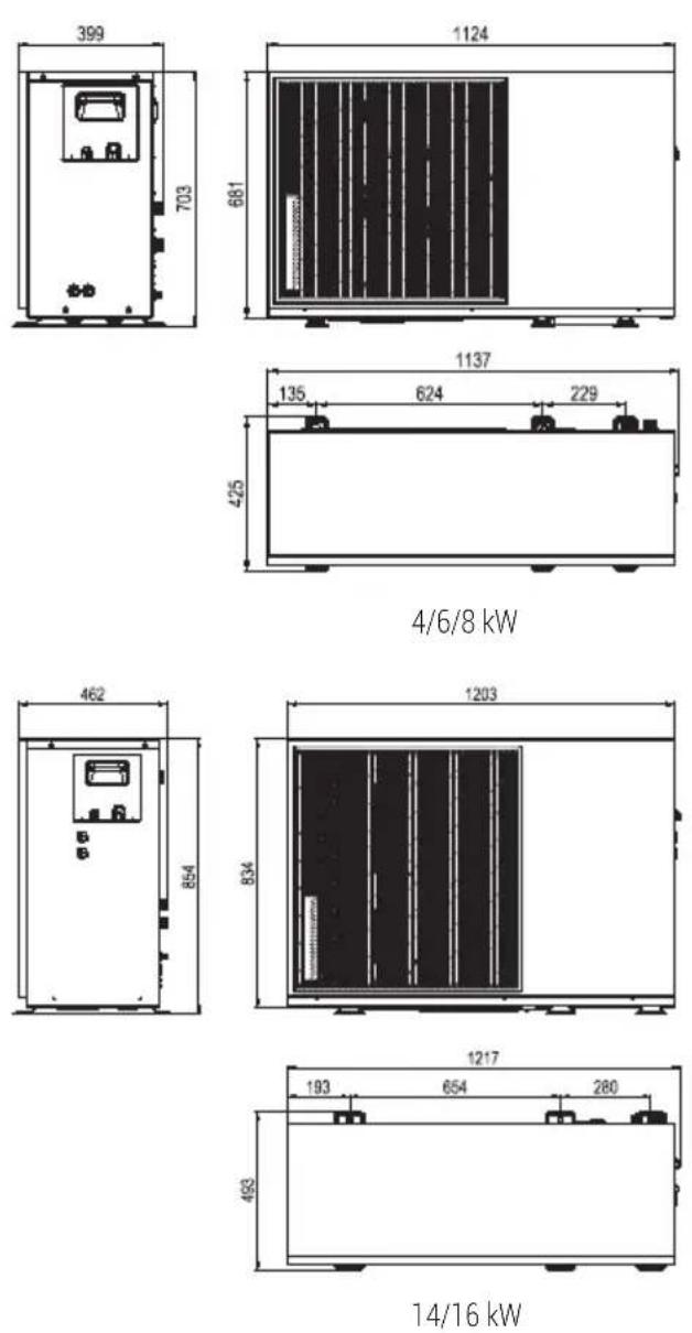
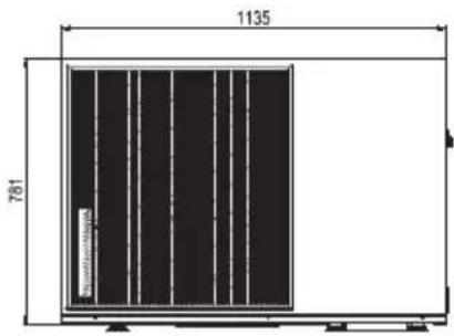
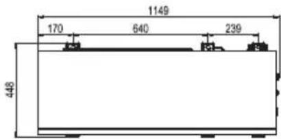
10/12 kW
7 Installation precautions
7.2 Installation requirements
- Check the strength and level of the installation ground so that the unit may not cause any vibrations or noise during its operation.
- In accordance with the foundation drawing in the figure, fix the unit securely by means of foundation bolts. (Prepare four sets each of 10 Expansion bolts, nuts and washers which are readily available in the market.)
- Screw in the foundation bolts until their length is 20 mm from the foundation surface.
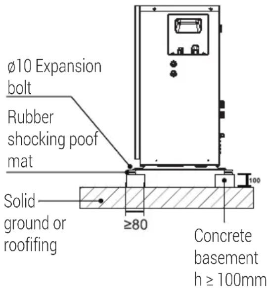
(unit: mm)
natural_image
Diagram of a window with vertical slats and a horizontal base, no text or symbols present- Location guidance on not installing unit adjacent to a bedroom or living room due to noise and vibration.
7 Installation precautions
7.3 Drain hole position
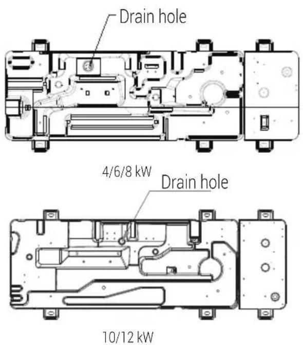
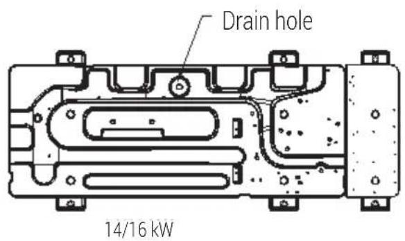
Note:

It's necessary to install an electrical heating belt if water can't drain out in cold weather even the big drain hole has opened.
7 Installation precautions
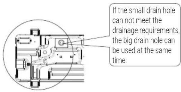
7.4 Servicingspace requirements
7.4.1 In case of stacked installation
1) In case obstacles exist in front of the outlet sid
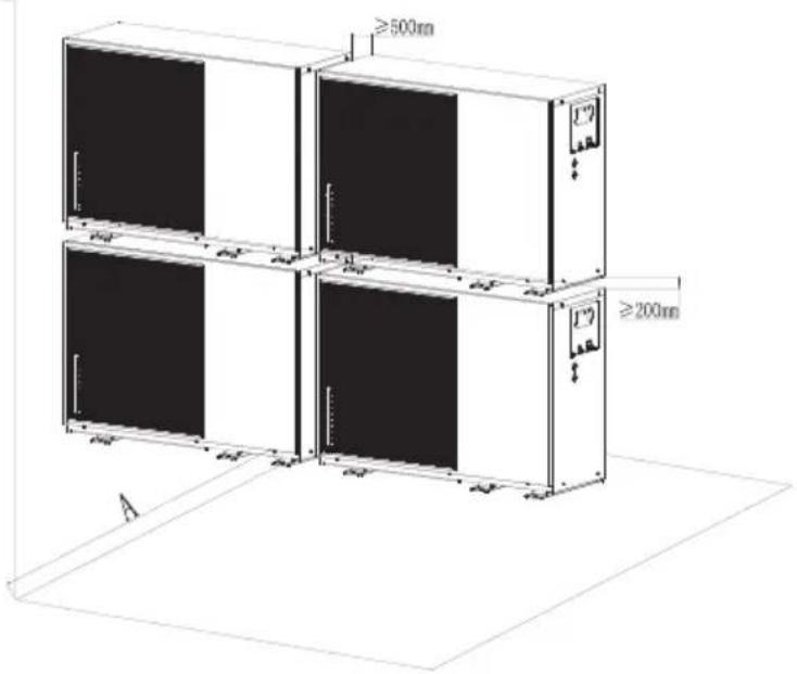
2) In case obstacles exist in front of the air inle
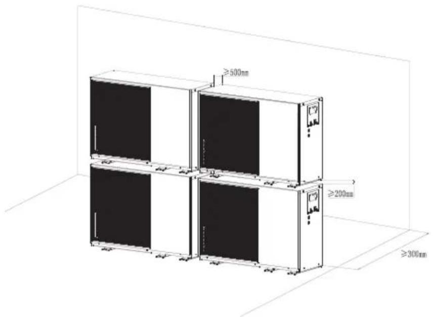
7 Installation precautions
| Unit A (mm) | |
| 4~12kW ≥1000 | |
| 14~16kW ≥1500 |
7.4.2 In case of multiple-row installation (for roof top use, etc.)
In case of installing multiple units in lateral connection per row.
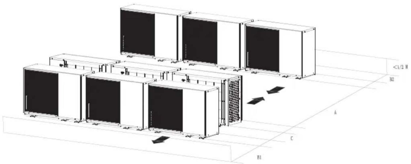
| Unit A (mm) B1 (mm) B2 (mm) C (mm) | ||
| 4~12kW ≥2500 ≥1000 | ≥300 ≥600 | |
| 14~16kW ≥3000 ≥1500 | ||
7 Installation precautions
7.5 Reference: Recommended water circulation characteristics during installation.
| MAXIMUM CHEMICAL-PHYSICAL PROPERTIES ALLOWED FOR THE CIRCUIT WATER | |
| PH 7.5 - 9 | |
| Electrical conductivity | 100 - 500 μs/cm |
| Total hardness 4,5 | -8,5 dH |
| Temperature <65°C | |
| Oxygen content <0,1 | ppm |
| Max glycol quantity 10% | |
| Phosphates (PO4) <2 | ppm |
| Manganese(Mn) <0,05 ppm | |
| Iron (Fe) <0,3 ppm | |
| Alkalinity (HCO3) 70 | -300 ppm |
| Chloride ions (Cl-) <50 ppm | |
| Sulphate ions (SO4) <50 ppm | |
| Sulphide ions (S) No one | |
| Ammonium ions (NH4) | No one |
| silica (SiO2) | <30 ppm |

Note:
We must maintain and inspect the unit regularly to ensure equipment safety. It is strongly recommended that the unit must be inspected after 1 month, 4 months, 6 months and 12 months of operation.
8 Typical applications
The application examples given below are for illustration only.
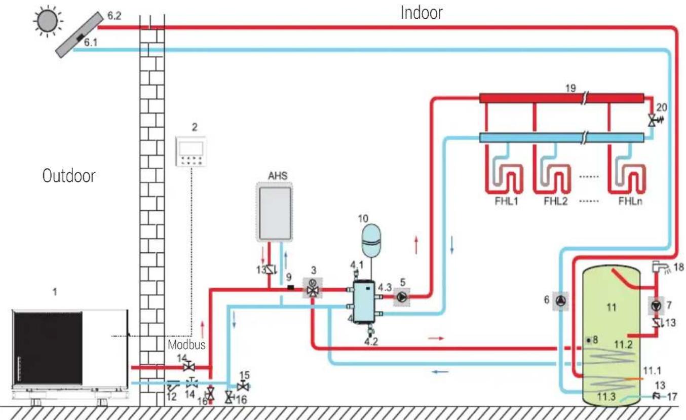
8.1 Application 1
flowchart
graph TD
    A["Outdoor"] --> B["Modbus"]
    B --> C["AHS"]
    C --> D["13"]
    C --> E["9"]
    C --> F["3"]
    C --> G["4.1"]
    C --> H["4.2"]
    C --> I["5"]
    C --> J["10"]
    J --> K["4.3"]
    J --> L["4.2"]
    M["Indoor"] --> N["FHL1"]
    M --> O["FHL2"]
    M --> P["FHLn"]
    N --> Q["19"]
    O --> R["20"]
    P --> S["18"]
    Q --> T["6"]
    R --> U["7"]
    S --> V["13"]
    T --> W["11"]
    U --> X["11.2"]
    V --> Y["11.1"]
    W --> Z["11.3"]
    X --> AA["11.2"]
    Y --> AB["11.3"]
    Z --> AC["11.3"]
| Code Assembly unit Code Assembly unit | ||
| 1 Main unit 11 Domestic hot water tank (Field supply) | ||
| 2 User interface 11.1 | WTH: Domestic hot water tank booster heater (Field supply) | |
| 3 SV1:3-way valve (Field supply) 11.2 Coil 1, heat exchanger for heat pump | ||
| 4 Balance tank (Field supply) 11.3 Coil 2, heat exchanger for Solar energy | ||
| 4.1 Automatic air purge valve 12 Filter (Accessory) | ||
| 4.2 Drainage valve 13 Check valve (Field supply) | ||
| 4.3 | TE1: Balance tank upper temperature sensor (optional reserved) | 14 Shut-off valve (Field supply) |
| 5 | P_o: Outside circulation pump (Field supply) | 15 Filling valve (Field supply) |
| 6 P_s: Solar pump (Field supply) | 16 Drainage valve (Field supply) | |
| 6.1 | Tsolar: Solar temperature sensor (optional) | 17 Tap water inlet pipe (Field supply)) |
8 Typical applications
| Code Assembly unit Code Assembly unit | |||
| 6.2 Solar panel (Field supply) 18 Hot water tap (Field supply) | |||
| 7 P_d: DHW pipe pump (Field supply) 19 Collector/distributor (Field supply) | |||
| 8 | TW: Domestic water tank temperature sensor (Accessory) | 20 Bypass valve (Field supply) | |
| FHL1...n | Floor heating loop (Field supply) | ||
| 9 | TC: Total water flow temperature sensor (Optional) | ||
| AHS Auxiliary heat source (Field supply) | |||
| 10 Expansion vessel (Field supply) | |||
- Space heating
The ON/OFF signal and operation mode and temperature setting are set on the user interface. P_o keeps running as long as the unit is ON for space heating, SV1 keeps OFF.
• Domestic water heating
The ON/OFF signal and target tank water temperature (TWS) are set on the user interface. P_o stops running as long as the unit is ON for domestic water heating, SV1 keeps ON.
• AHS (auxiliary heat source) control
The AHS function is set on the wired controller (See "wired controller manual")
1) When the AHS is set to be valid only for heating mode, AHS can be turned on in the following ways:
a. Turn on the AHS via BACKUPHEATER function on the user interface;
b. AHS will be turned on automatically if initial water temperature is too low or target water temperature is too high at low ambient temperature.
P_o keeps running as long as the AHS is ON, SV1 keeps OFF.
2) When the AHS is set to be valid for heating mode and DHW mode. In heating mode, AHS control is same as part 1); In DHW mode, AHS will be turned on automatically when the initial domestic water temperature TW is too low or the target domestic water temperature is too high at low ambient temperature. P_o stops running, SV1 keeps ON.
• WTH (tank booster heater) control
The WTH function is set on the user interface. (See "wired controller manual")
1) When the WTH is set to be valid, WTH can be turned on via BACKUPHEATER function on the user interface; In DHW mode, WTH will be turned on automatically when the initial domestic water temperature TW is too low or the target domestic water temperature is too high at low ambient temperature.
8 Typical applications
• Solar energy control
Hydraulic module recognizes solar energy signal by judging Tsolar or receiving SL1SL2 signal from user interface. The recognition method can be set via SOLAR INPUT on the user interface. Please refer to 9.7.6/1). For solar energy input signal" for wiring.
1) When Tsolar is set to be valid, Solar energy turns ON when Tsolar is high enough, P_s starts running; Solar energy turns OFF when Tsolar is low, P_s stops running.
2) When SL1SL2 control is set to be valid, Solar energy turns ON after receiving Solar kit signal from user interface, P_s starts running; Without solar kit signal. Solar energy turns OFF, P_s stops running.

Warning:
The highest outlet water temperature may reach 70^ C, please beware of burn.

Note:
Make sure to fit the (SV1) 3-way valve correctly. For more details, please refer to 9.7.6 "Connection for other components. At extremely low ambient temperature, the domestic hot water is exclusively heated by WTH, which assures that heat pump can be used for space heating with full capacity.
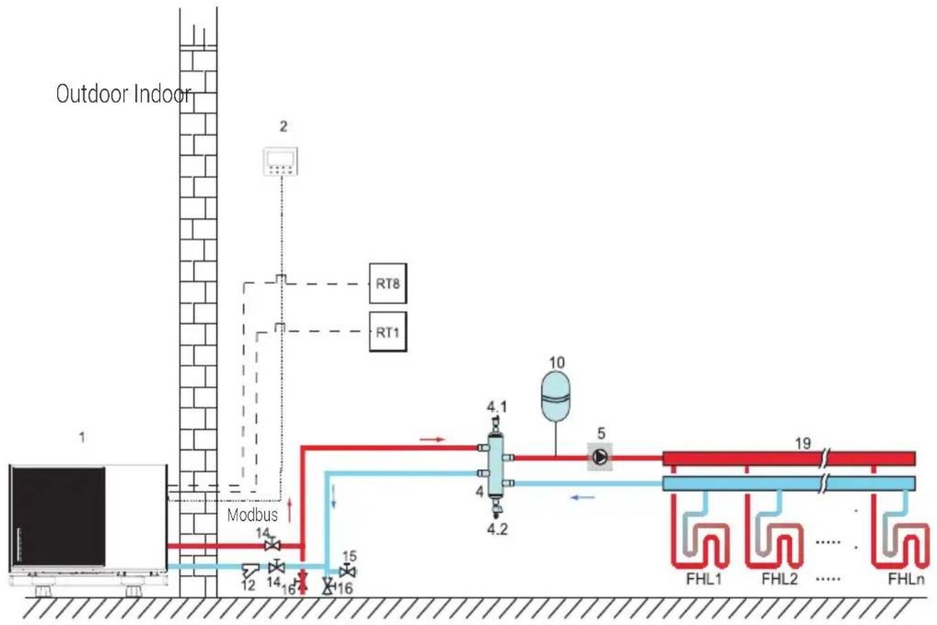
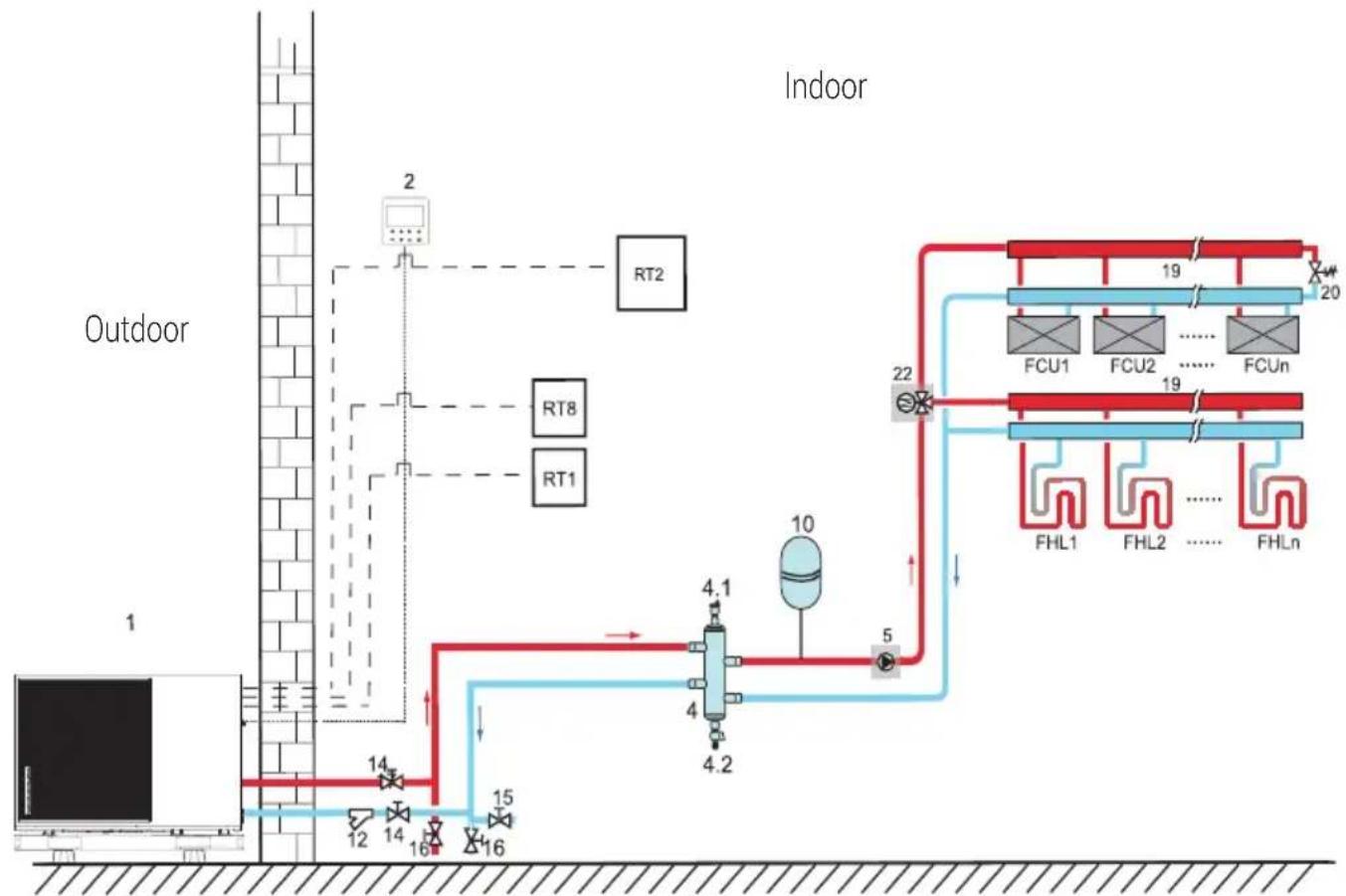
8.2 Application 2
ROOM THERMOSTAT Control for Space heating or cooling need to be set on the user interface. It can be set in three ways: MODE SET/ONE ZONE/TWO ZONE. The monobloc can be connected to a high voltage room thermostat and a low voltage room thermostat. Please refer to 9.7.6/5) "For room thermostat" for wiring. (see 10.5.7 "ROOM THERMOSTAT" for setting)
8 Typical applications
8.2.1 One zone control
flowchart
graph TD
    A["Outdoor Indoor Tank"] --> B["Modbus"]
    B --> C["12"]
    B --> D["14"]
    B --> E["16"]
    B --> F["15"]
    B --> G["10"]
    G --> H["4.1"]
    G --> I["4.2"]
    G --> J["5"]
    G --> K["19"]
    K --> L["FHL1"]
    K --> M["FHL2"]
    K --> N["FHLn"]
    B --> O["RT8"]
    B --> P["RT1"]
| Code Assembly unit Code Assembly unit | ||
| 1 Main unit 14 Shut-off valve (Field supply) | ||
| 2 User interface 15 Filling valve (Field supply) | ||
| 4 Balance tank (Field supply) 16 Drainage valve (Field supply) | ||
| 4.1 Automatic air purge valve 19 Collector/distributor (Field supply) | ||
| 4.2 Drainage valve RT 1 Low voltage room thermostat | (Field supply) | |
| 5 P_o: Outside circulation pump (Field supply) | RT8 | High voltage room thermostat (Field supply) |
| 10 Expansion vessel (Field supply) | FHL 1...n | Floor heating loop (Field supply) |
| 12 Filter (Accessory) |
8 Typical applications
- Space heating
One zone control: the unit ON/OFF is controlled by the room thermostat, cooling or heating mode and outlet water temperature are set on the user interface. System is ON when any "HL" of all the thermostats closes. When all "HL" open, system turns OFF.
- The circulation pumps operation When the system is ON, which means any "HL" of all the thermostats closes, P_o starts running; When the system is OFF, which means all "HL" close, P_o stops running.
8.2.2 Mode set control
flowchart
graph TD
    A["Outdoor"] --> B["1"]
    B --> C["2"]
    C --> D["RT1"]
    C --> E["RT8"]
    C --> F["RT2"]
    G["Indoor"] --> H["10"]
    H --> I["4.1"]
    H --> J["4.2"]
    H --> K["5"]
    H --> L["22"]
    L --> M["FCU1"]
    L --> N["FCU2"]
    L --> O["FCUn"]
    M --> P["FHL1"]
    M --> Q["FHL2"]
    M --> R["FHLn"]
    style A fill:#f9f,stroke:#333
    style G fill:#ccf,stroke:#333
    style H fill:#cfc,stroke:#333
    style I fill:#fcc,stroke:#333
    style J fill:#fcc,stroke:#333
    style K fill:#fcc,stroke:#333
    style L fill:#cff,stroke:#333
    style M fill:#ffc,stroke:#333
    style N fill:#ffc,stroke:#333
    style O fill:#ffc,stroke:#333
    style P fill:#fff,stroke:#333
    style Q fill:#fff,stroke:#333
    style R fill:#fff,stroke:#333
| Code Assembly unit Code Assembly unit | ||
| 1 Main unit 16 Drainage valve (Field supply) | ||
| 2 User interface 19 Collector/distributor | ||
| 4 Balance tank (Field supply) 20 Bypass valve (Field supply) | ||
| 4.1 Automatic air purge valve 22 SV2: 3-way valve (Field supply) | ||
| 4.2 Drainage valve RT 1/2 Low voltage room thermostat | ||
| 5 | P_o: Outside circulation pump (Field supply) | RT8 High voltage room thermostat |
8 Typical applications
| 10 Expansion vessel (Field supply) | FHL1...n | Floor heating loop (Field supply) |
| 12 Filter (Accessory) | FCU1...n | Fan coil unit (Field supply) |
| 14 Shut-off valve (Field supply) | ||
| 15 Filling valve (Field supply) |
- Space heating
Cooling or heating mode is set via the room thermostat, water temperature is set on the user interface.
1) When any "CL" of all the thermostats close, system will be set at cooling mode.
2) When any "HL" of all the thermostats close and all "CL" open, system will be set at heating mode.
• The circulation pumps operation
1) When the system is in cooling mode, which means any "CL" of all the thermostats closes, SV2 keeps ON, P_o starts running.
2) When the system is in heating mode, which means one or more "HL" close and all "CL" open, SV2 keeps OFF, P_o starts running.
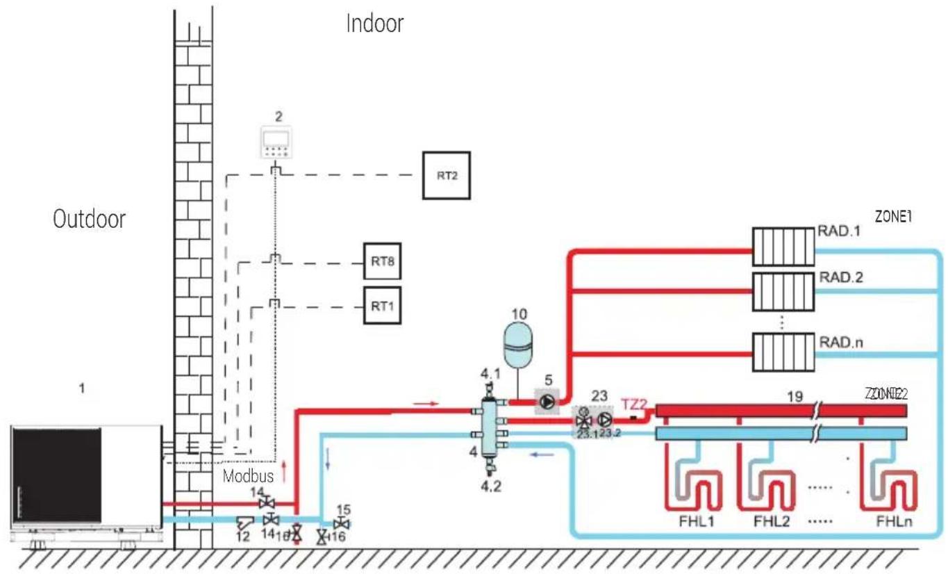
8.2.3 Double zone control
flowchart
graph TD
    A["Indoor"] --> B["Outdoor"]
    B --> C["Modbus"]
    C --> D["14"]
    C --> E["12"]
    C --> F["14"]
    C --> G["16"]
    D --> H["10"]
    E --> I["4.1"]
    F --> J["4.2"]
    G --> K["5"]
    H --> L["TZ2"]
    I --> L
    J --> L
    K --> L
    L --> M["ZONE1"]
    L --> N["ZONE2"]
    L --> O["FHL1"]
    L --> P["FHL2"]
    L --> Q["FHLn"]
8 Typical applications
| Code Assembly unit Code Assembly unit | ||
| 1 Main unit 19 Collector/distributor (Field supply) | ||
| 2 User interface 21 Thermostat transfer board (Field supply) | ||
| 4 Balance tank (Field supply) 23 Mixing station (Field supply) | ||
| 4.1 Automatic air purge valve 23.1 SV3: Mixing valve (Field supply) | ||
| 4.2 Drainage valve 23.2 P_c: zone 2 circulation pump | (Field supply) | |
| 5 P_o: zone 1 circulation pump(Field supply) | RT 1/2 Low voltage room thermostat(Field supply) | |
| 10 Expansion vessel (Field supply) | RT8 | High voltage room thermostat(Field supply) |
| 12 Filter (Accessory) TZ2 | Zone | 2 water flow temperature sensor(Field supply) |
| 14 Shut-off valve (Field supply) FHL | 1...n | Floor heating loop (Field supply) |
| 15 Filling valve (Field supply) RAD. | 1...n | Radiator (Field supply) |
| 16 Drainage valve (Field supply) | ||
• Space heating
Zone1 can operate in cooling mode or heating mode, while zone2 can only operate in heating mode; While installation, for all thermostats in zone1, only "H, L" terminals need to be connected. For all thermostats in zone2, only "C, L" terminals need to be connected.
1) The ON/OFF of zone1 is controlled by the room thermostats in zone1. When any "HL" of all thermostats in zone1 closes, zone1 turns ON. When all "HL" turn OFF, zone1 turns OFF; Target temperature and operation mode are set on the user interface.
2) In heating mode, the ON/OFF of zone2 is controlled by the room thermostats in zone2. When any "CL" of all thermostats in zone2 closes, zone2 tums ON. When all "CL" open, zone2 tums OFF. Target temperature is set on the user interface; Zone 2 can only operate in heating mode. When cooling mode is set on the user interface, zone2 keeps in OFF status.
8 Typical applications
• The circulation pump operation
When zone 1 is ON, P_o starts running; When zone 1 is OFF, P_o stops running;
When zone 2 is ON, sV3 switches between ON and OFF according to the set TZ2, P_C keeps ON; When zone 2 is OFF, Sv3 is OFF, P_c stops running.
The floor heating loops require a lower water temperature in heating mode compared to radiators or fan coil unit. To achieve these two set points, a mixing station is used to adapt the water temperature according to requirements of the floor heating loops. The radiators are directly connected to the unit water circuit and the floor heating loops are after the mixing station. The mixing station is controlled by the unit.

Warning:
- Make sure to connect the SV2/SV3 terminals in the wired controller correctly, please refer to 9.7.6/2) for 3-way valve SV1, SV2, SV3.
- Thermostat wires to the correct terminals and to configure the ROOM THERMOSTAT in the wired controller correctly. Wiring of the room thermostat should follow method A/B/C as described in 9.7.6 "Connection for other components/5) For room thermostat".
Notes:
- Zone 2 can only operate in heating mode. When cooling mode is set on user interface and zone 1 is OFF, "CL" in zone 2 closes, system still keeps "OFF". While installation, the wiring of thermostats for zone 1 and zone 2 must be correct.
- Drainage valve (2) must be installed at the lowest position of the piping system.
8 Typical applications
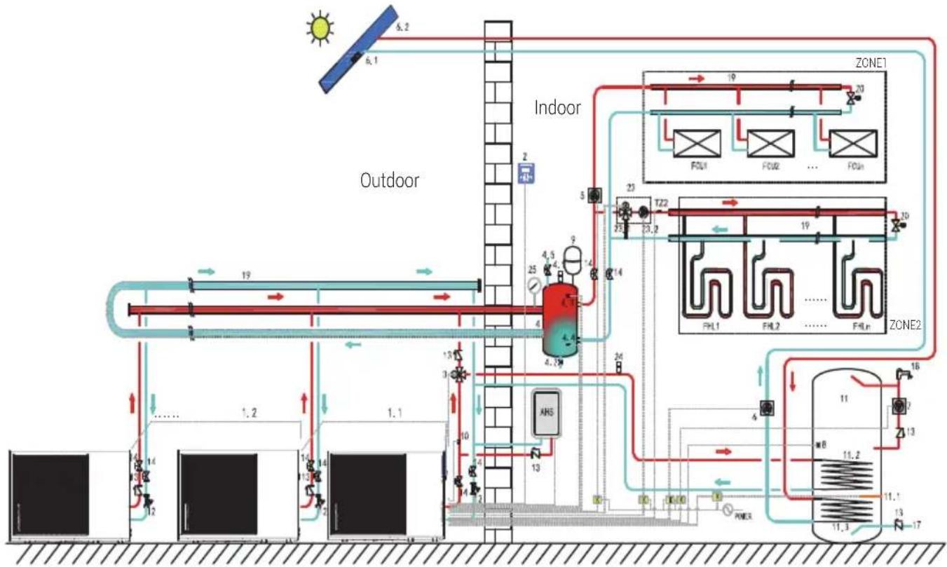
8.3 Application 3
8.3.1 Cascade application
8.3.1.1 Hydraulic system
flowchart
graph TD
    A["Outdoor"] --> B["Indoor"]
    B --> C["Zone1"]
    B --> D["Zone2"]
    B --> E["PHL1"]
    B --> F["PHL2"]
    B --> G["PHLn"]
    B --> H["AN5"]
    B --> I["19"]
    B --> J["20"]
    B --> K["23"]
    B --> L["24"]
    B --> M["25"]
    B --> N["26"]
    B --> O["27"]
    B --> P["28"]
    B --> Q["29"]
    B --> R["30"]
    B --> S["31"]
    B --> T["32"]
    B --> U["33"]
    B --> V["34"]
    B --> W["35"]
    B --> X["36"]
    B --> Y["37"]
    B --> Z["38"]
    B --> AA["39"]
    B --> AB["40"]
    B --> AC["41"]
    B --> AD["42"]
    B --> AE["43"]
    B --> AF["44"]
    B --> AG["45"]
    B --> AH["46"]
    B --> AI["47"]
    B --> AJ["48"]
    B --> AK["49"]
    B --> AL["50"]
    B --> AM["51"]
    B --> AN["52"]
    B --> AO["53"]
    B --> AP["54"]
    B --> AQ["55"]
    B --> AR["56"]
    B --> AS["57"]
    B --> AT["58"]
    B --> AU["59"]
    B --> AV["60"]
    B --> AW["61"]
    B --> AX["62"]
    B --> AY["63"]
    B --> AZ["64"]
    B --> BA["65"]
    B --> BB["66"]
    B --> BC["67"]
    B --> BD["68"]
    B --> BE["69"]
    B --> BF["70"]
    B --> BG["71"]
    B --> BH["72"]
    B --> BI["73"]
    B --> BJ["74"]
    B --> BK["75"]
    B --> BL["76"]
    B --> BM["77"]
    B --> BN["78"]
    B --> BO["79"]
    B --> BP["80"]
    B --> BQ["81"]
    B --> BR["82"]
    B --> BS["83"]
    B --> BT["84"]
    B --> BU["85"]
    B --> BV["86"]
    B --> BW["87"]
    B --> BX["88"]
    B --> BY["89"]
    B --> BZ["90"]
    B --> CA["91"]
    B --> CB["92"]
    B --> CC["93"]
    B --> CD["94"]
    B --> CE["95"]
    B --> CF["96"]
    B --> CG["97"]
    B --> CH["98"]
    B --> CI["99"]
    B --> CJ["100"]
Cascade hydraulic system
| Legend | |||
| 1.1 Master unit 11.3 Coil 2: heat exchanger for solar water | heater kit | ||
| 1.2...n Slave unit 12 Filter (Accessor y) | |||
| 2 User interface 13 Check valve (Field supply) | |||
| 3 SV1: 3-way valve (Field supply) 14 Shut-off valve (Field supply) | |||
| 4 Balance tank (Field supply) 17 Tap water inlet pipe (Field supply) | |||
| 4.1 Automatc bleed valve 18 Hot water tap (Field supply) | |||
| 4.2 Drainage valve | 19 Collector/Distributor (Field supply) | ||
| 4.3 TE1: Balance tank upper temperature sensor for CASCADE application | 20 Bypass valve (Field supply) | ||
8 Typical applications
| Legend | |||
| 4.4 TE2 | Balance tank lower temperature sensor (reserved) | 23 Mixing station (Field supply) | |
| 4.5 Filling valve 23.1 SV3: Mixing valve (Fieldsupply) | |||
| 5 P_O: | Outside circulaton pump (Field supply) | 23.2 P_C: Zone B circulation pump (Field supply) | |
| 6 P_S: | Solar pump (Field supply) 24 Automatic | bleed valve (Field supply) | |
| 6.1 Tsolar: Solar temperature sensor (Optional) | 25 Water manometer (Field supply) | ||
| 6.2 solar collector (Field supply) TZ2 Zone B water flow t emperature sensor (Optional) | |||
| 7 P_D: | DHW pipe pump (Field supply) RAD 1...n | Radiator (Field supply) | |
| 8 TW: | Domestic water tank temperature sensor (Accessory) | FHL 1...n Floor heating loop (Field supply) | |
| 9 Expansion vessel (Field supply) K Contactor (Field supply) | |||
| 10 TC: | Total water flow temperature sensor (optional) | ZONE 1 The space cooling or heating mode | |
| 11 Domestic water tank (Field supply) ZONE 2 The space heating mode | |||
| 11.1 WTH: | Domestic water tank heater | AHS Auxiliary heat source (Field supply) | |
| 11.2 Coil: | 1: heat exchanger for heat pump | ||

Notes:
- The example is just for application illustration, please confirm the exact installation method according to the installation manual.
• At most 8 units can be controlled in group. - The group control system can control and view the operation of the entire system only by connecting the master to the wire controller.
- If the DHW function is required, the water tank can only be connected to the master unit water circuit through a 3-way valve, and controlled by the master unit.
- If AHS is needed, it can only be connected to the master waterway and controlled by the master unit.
- The TE1 temperature sensor must be installed in the parallel system (otherwise unit cannot be started).
- If the balance tank is too large, TE2 needs to be added in order to improve the control accuracy.
• TE2 is set in the lower part of the balance tank. - The water inlet and outlet pipe joints of each unit of the parallel system should be connected with soft connections and one-way valves must be installed at the water outlet pipe.
• Space heating
All salve units can operate in space heating mode. The operation mode and setting temperature are set on the user interface (2). Due to changes of the outdoor temperature and therequired load indoors, multiple outdoor units may opreate at different times.
In cooling mode with FCU, SV3 (23.1) and P_C (23.2) keep OFF, P_O (5) keeps ON;
In heating mode, when both ZONE 1 and ZONE 2 work, P_C (23.2) and P_O (5) keep OFF, SV3 (23.1) switches between ON and OFF according to the set TZ2.
In heating mode, when only ZONE 1 work, P_O (5) keep ON, SV3 (23.1) and P_C (23.2) keep OFF.
In heating mode, when only ZONE 2 work, P_O (5) keep OFF, SV3 (23.1) and P_C (23.2) keep ON. switches between ON and OFF. according to the set TZ2.
• Domestic water heating
Only master unit (1.1) can operate in DHW mode. Desired hot water temperature is set on the ser interface (2). In DHW mode, SV1 (3) keeps ON. When master unit operated in DHW mode, slave units can operate in space cooling/heating mode.
8 Typical applications
- AHS control
AHS is only controlled by master unit. When master unit operates in DHW mode, AHS can only be used for producing domestic hot water; when master unit operates in heating mode, AHS can only be used for heating mode.
- WTH control
WTH is only controlled by master unit.
- Solar energy control
Solar water heater kit is only controlled by Master unit.
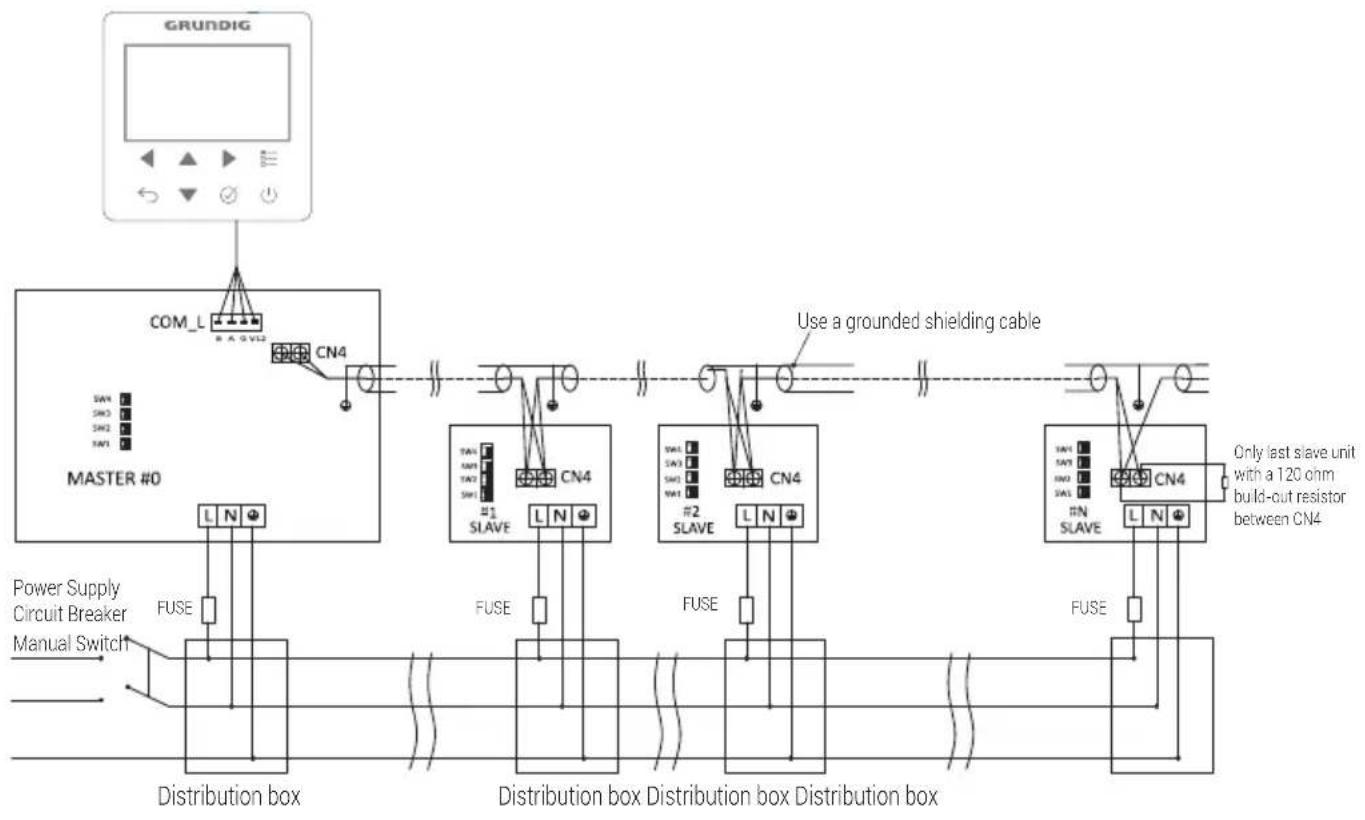
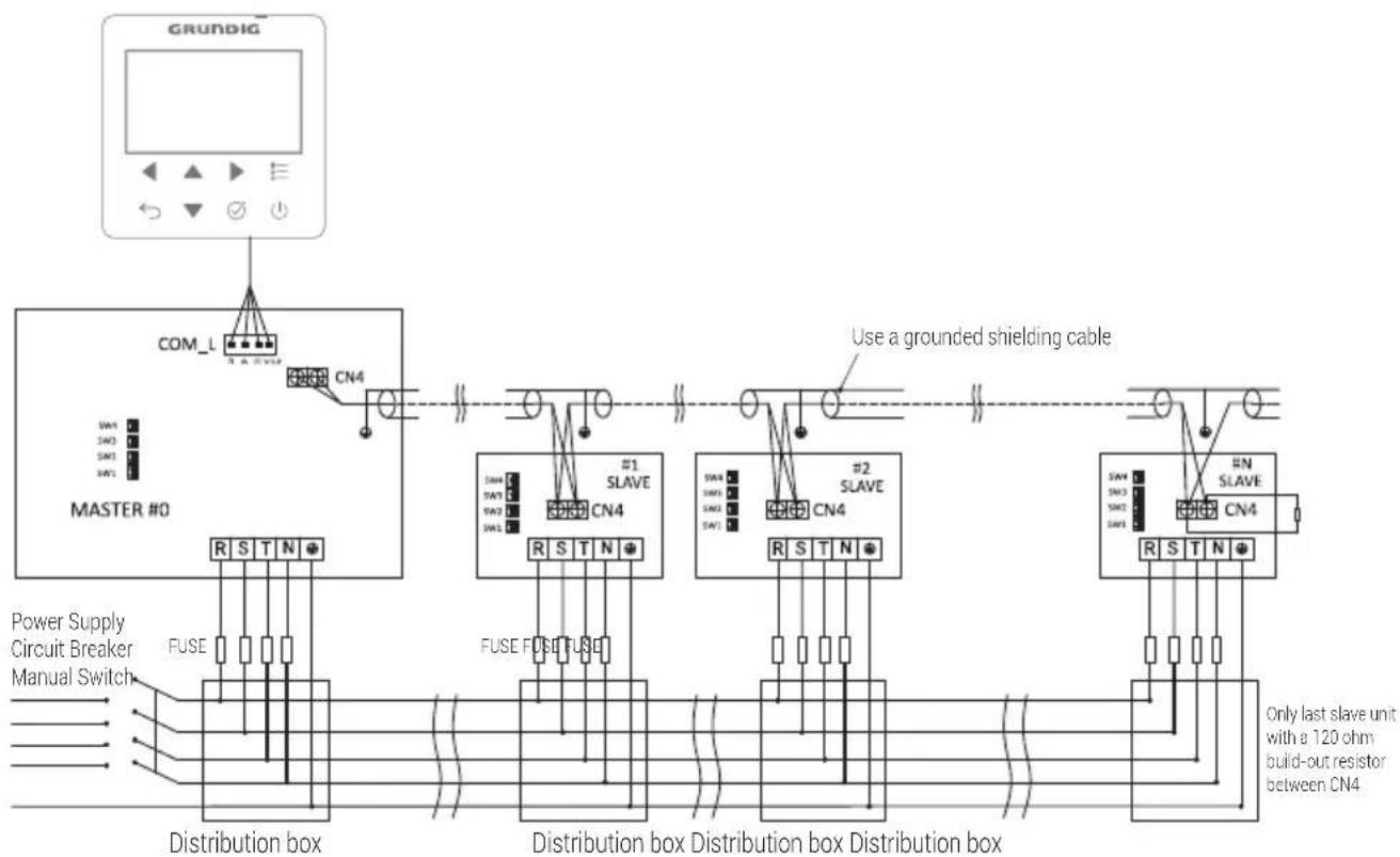
8.3.2 Wiring
flowchart
graph TD
    A["GRUNDIG"] --> B["MASTER #0"]
    B --> C["Distribution box"]
    C --> D["Power Supply Circuit Breaker Manual Switch"]
    B --> E["Use a grounded shielding cable"]
    E --> F["Only last slave unit with a 120 ohm build-out resistor between CN4"]
    subgraph Distribution box
        G["CUVE L N"]
        H["FUSE"]
        I["SAV"]
        J["SW3"]
        K["SW2"]
        L["SW1"]
    end
    subgraph Distribution box Distribution box
        M["CUVE #1 SLAVE"]
        N["FUSE"]
        O["SAV"]
        P["SW3"]
        Q["SW2"]
        R["SW1"]
        S["SNL"]
        T["SN4"]
        U["FUSE"]
        V["SNL"]
        W["FUSE"]
    end
Cascade system wiring diagram for single phase 4\~16kW models
8 Typical applications
| Dip Switch | |||
| SW4 | 1 | SINGLE OFF | |
| CASCADE ON | |||
| 2/3/4 | MASTER#0 OFF/OFF/OFF | ||
| SLAVE#1 OFF/OFF/ON | |||
| SLAVE#2 OFF/ON/OFF | |||
| SLAVE#3 OFF/ON/ON | |||
| SLAVE#4 ON/OFF/OFF | |||
| SLAVE#5 ON/OFF/ON | |||
| SLAVE#6 ON/ON/OFF | |||
| SLAVE#7 ON/ON/ON | |||
flowchart
graph TD
    A["GRUNDIG"] --> B["MASTER #0"]
    B --> C["Distribution box"]
    C --> D["Use a grounded shielding cable"]
    D --> E["Distribution box"]
    E --> F["Power Supply Circuit Breaker Manual Switch"]
    E --> G["Distribution box"]
    G --> H["Only last slave unit with a 120 ohm build-out resistor between CN4"]
Cascade system wiring diagram for three phase 10\~16kW models
8 Typical applications
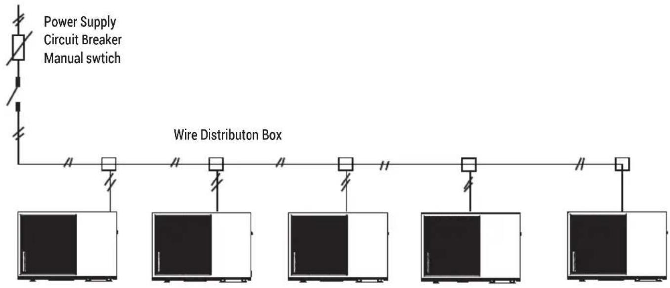
8.3.3 Power supply
8.4 Balance tank volume requirement
| NO. model Balance tank (L) | |
| 1 4~10 kW ≥25 | |
| 2 12~16 kW ≥40 |
9 Overview of the unit
9.1 Disassembling the unit
Door 1 To access the compressor and electrical parts and hydraulic compartment

Warning:
- Switch off all power — i.e. unit power supply and backup heater and domestic hot water tank power supply (if applicable) — before removing door 1
• Parts inside the unit may be hot.
9 Overview of the unit
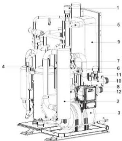
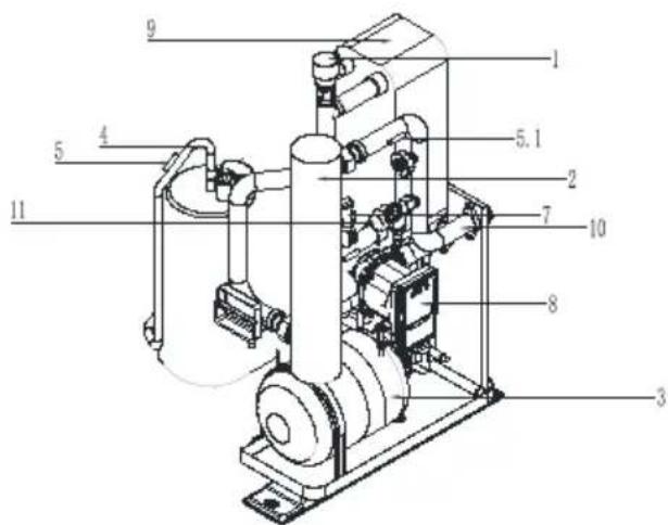
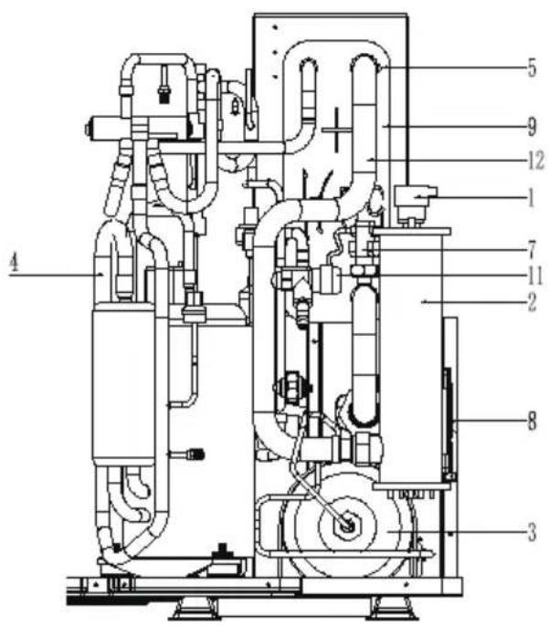
9.2 Main components
9.2.1 Hydraulic module
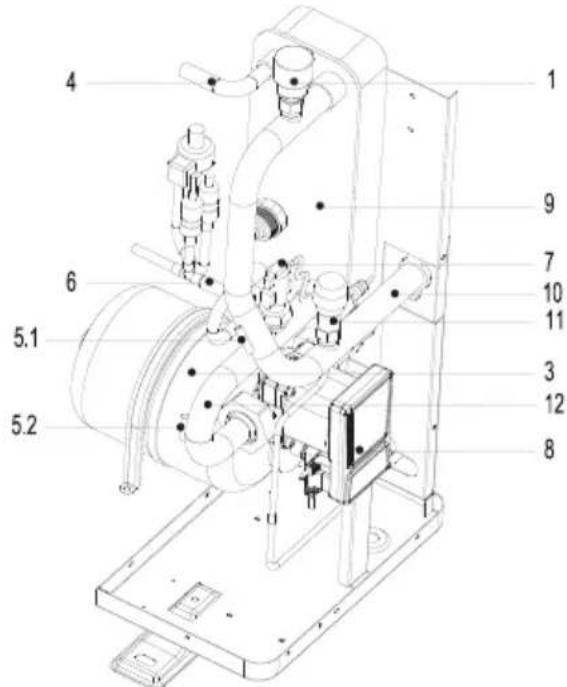
4\~6 kW without backup heater
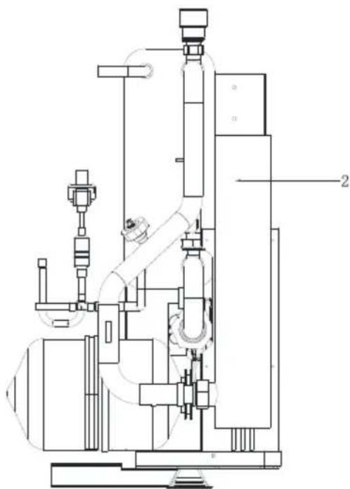
natural_image
Technical line drawing of an industrial machine or processing unit with no visible text or symbols4\~6 kW with backup heater (optional)
10\~12 kW with backup heater (standard)
14\~16 kW with backup heater (standard)
9 Overview of the unit
10\~12 kW (3-Phase) with backup heater (standard)

14\~16 kW (3-Phase) with backup heater (standard)
| Code Assembly unit Explanation | |
| 1 Automatic air purge valve | Remaining air in the water circuit will be automatically removed from the water circuit. |
| 2 Backup heater (optional) | Provides additional heating capacity when the heating capacity of the heat pump is insufficient due to very low outdoor temperature. Also protects the external water pipes from freezing. |
| 3 Expansion vessel Balances water system pressure. | |
| 4 Refrigerant gas pipe / | |
| 5 Temperature sensor | Three temperature sensors determine the water and refrigerant temperature at various points in the water circuit. |
| 6 Refrigerant liquid pipe / | |
| 7 Flow switch | Detects water flow rate to protect compressor and water pump in the event of insufficient water flow. |
| 8 Pump Circulates water in the water circuit. | |
9 Overview of the unit
| Code Assembly unit Explanation | |
| 9 Plate heat exchanger Transfer heat from the refrigerant to the water. | |
| 10 Water outlet pipe / | |
| 11 Pressure relief valve | Prevents excessive water pressure by opening at 3 bar and discharging water from the water circuit. |
| 12 Water inlet pipe / | |
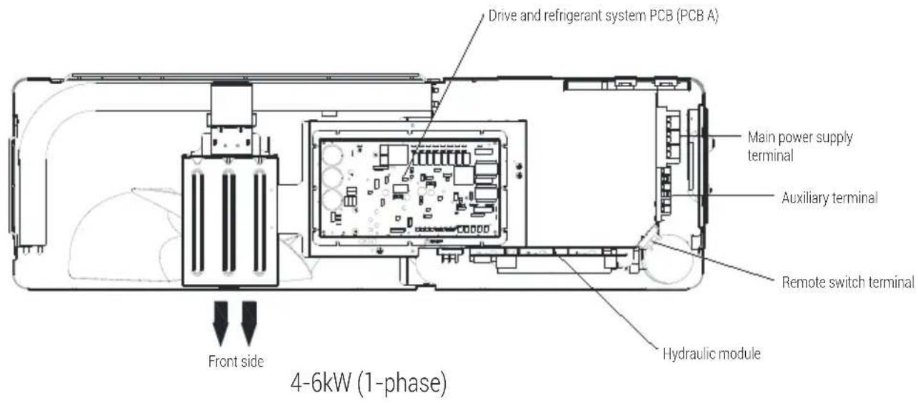
9.3 Electronic control box

Note:
The picture is for reference only, please refer to the actual product.
9 Overview of the unit

9 Overview of the unit
9 Overview of the unit
PCB specification
| Model/Number 4kW/6kW 8kW/10kW 12kW | 14kW/16kW | 10/12/14kW/16kW(3-Phase) | ||
| Refrigerant system module | 111 | 1 | 1 | |
| Inverter module | 1 | |||
| DC Fan drive board 1 | ||||
| Hydraulic module PCB 11111 | ||||
| Total 22223 |
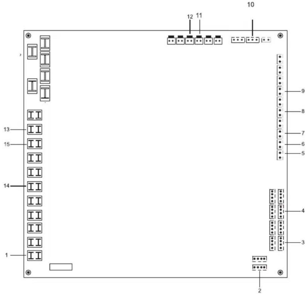
9.3.1 Main control board of hydraulic module
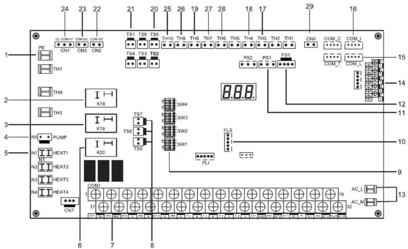
| Items Port label function | ||
| 1 PE Port for ground | ||
| 2 K18 | Relay for internal backup heater (IPH, 3 kW) | |
| 3 K19 | Relay for domestic water tank heater (3 kW) | |
| 4 Pump Power supply of internal pump | ||
| 5 HEAT 1 | Plate heat exchange anti-freezing heater | |
| Items Port label function | ||
| 6 K20 Relay | (Reserved,3 kW) | |
| 7 CON1 Terminals (Reserved) | ||
| 8 | TS7/TS9 High temperature protection switch for IPH | |
| TS8 High temperature protection switch for WTH | ||
| 9 SW1/2/3/4 Dipswitch | ||
| 10 FLS Program update | ||
| 11 PS1 Water pressure sensor | ||
| 12 FS1 Internal pump speed feedback | ||
| 13 AC Power supply | ||
| 14 U19 Communication ports | ||
| 15 COM_L Wired controller | ||
| 16 COM_I Communication port | ||
| 17 TH3 Inlet water temperature | ||
| 18 TH4 Outlet water temperature | ||
| 19 TH8 Domestic water tank temperature | ||
| 20 TS5 Remote switch | ||
| 21 TS1 Water flow switch | ||
| 22 SG Smart Grid | ||
| 23 EVU Commercial power | ||
| 24 CN1 Low voltage thermostat | ||
| 25 Tso | Solar temperature | |
| 26 TZ2 Zone 2 temperature | ||
| 27 TE2 Reserved | ||
| 28 TE1 Buffer temp. sensor for CASCADE | ||
| 29 CN4 Communication port | ||
9 Overview of the unit
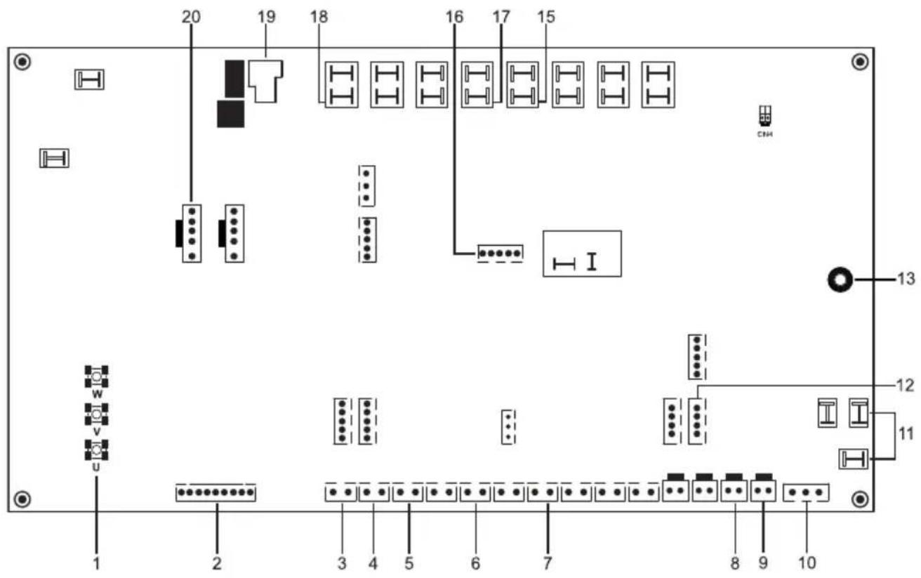
9.3.2 1-phase for 4-16kW units
1) PCB A, 4-6kW, Drive and refrigerant system PCB
| Items | Port label function | Items Port label function | |||
| 1 U/V/W Compressor output 11 AC Power supply | |||||
| 2 JTAG Drive program update 12 COM4 Communication with hydraulic module PCB | |||||
| 3 | TH1 | Coil temperature sensor | 13 | PE1 | Port for ground |
| 4 TH2 | Outdoor ambient temperature sensor | 14 | OUT4 | Filter components | |
| 5 TH3 | Refrigerant liquid temperature sensor | 15 | FLS | PCB Program update | |
| 6 | TH5 | Discharge temperature sensor | 16 | OUT5 | Chassis heater |
| 7 | TH7 | Suction temperature sensor | 17 | OUT8 | Crankcase heater |
| 8 | TS3 | HP2: Middle pressure switch | 18 | K9 | Relay for PFC |
| 9 | TS4 | HP1: High pressure switch | 19 | FAN1 | DC Fan |
| 10 | TS5 | LPS: low pressure sensor | 20 | L1 | Common mode inductance |
9 Overview of the unit
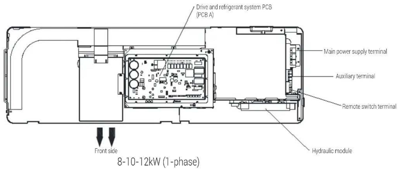
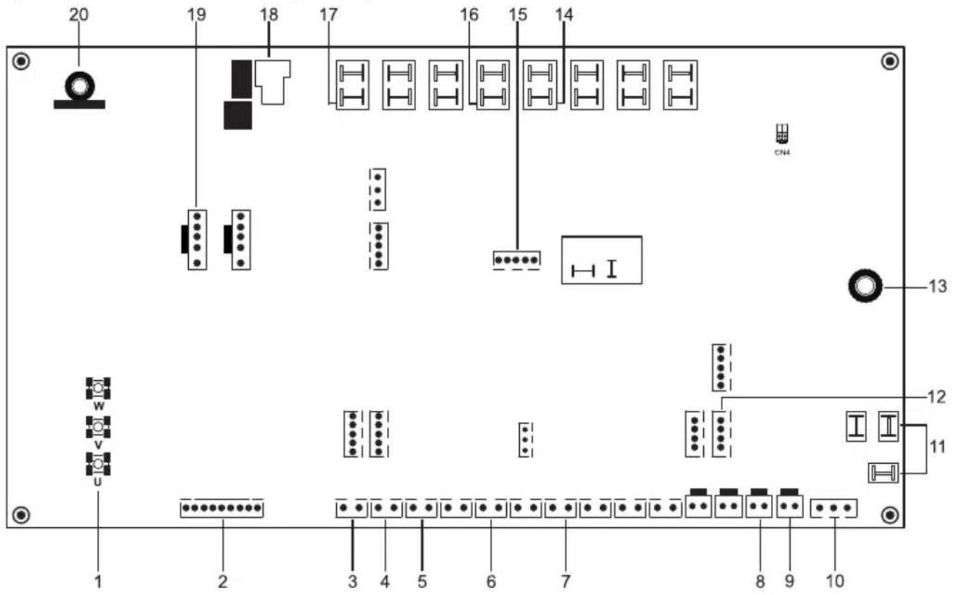
2) PCB A, 8-10-12kW, Drive and refrigerant system PCB

Note:
8kw and 10-12kw models has different PCB A but same connect ports
9 Overview of the unit
| Items Port label function |
| 1 U/V/W Compressor output |
| 2 JTAG Drive program update |
| 3 TH1 Coil temperature sensor |
| 4 TH2 Outdoor ambient temperature sensor |
| 5 TH3 Refrigerant liquid temperature sensor |
| 6 TH5 Discharge temperature sensor |
| 7 TH7 Suction temperature sensor |
| 8 TS3 HP2: Middle pressure switch |
| 9 TS4 HP1: High pressure switch |
| 10 TS5 LPS: low pressure sensor |
| 11 AC Power supply |
| 12 COM4 Communication with hydraulic module PCB |
| 13 PE1 Port for ground |
| 14 / Filter components |
| 15 OUT4 4- way valve |
| 16 FLS PCB Program update |
| 17 OUT 5 Chassis heater |
| 18 OUT 8 Crankcase heater |
| 19 K9 Relay for PFC |
| 20 FAN1 DC fan |
| 21 / Drive components |
9 Overview of the unit
3) PCB A, 14-16kW, Drive PCB
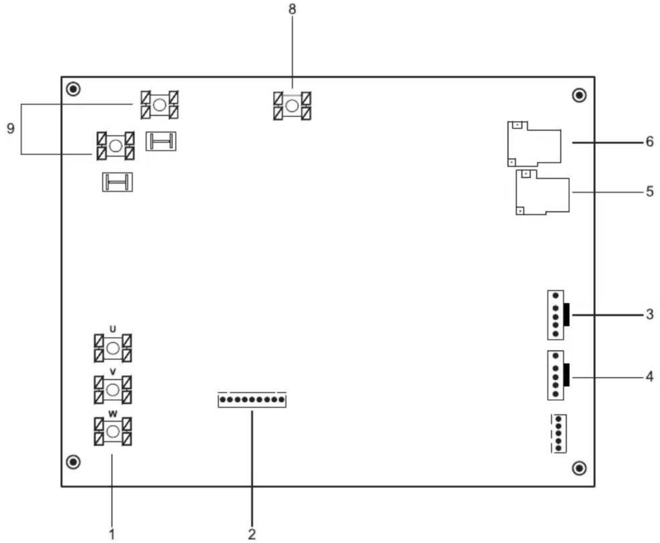
| Items Port label function | |
| 1 U/V/W Compressor output | |
| 2 JTAG Drive program update | |
| 3 FAN1 DC fan | |
| 4 FAN2 Reserved | |
| 5 K2 Relay for PFC | |
| 6 K1 Relay for PFC | |
| 7 / Filter components | |
| 8 PE Port for ground | |
| 9 AC Power supply | |
| 10 / Drive components |
9 Overview of the unit
4) PCB B, 14-16kW, Refrigerant system PCB
| Items Port label function | |
| 1 AC (L/N) Power supply | |
| 2 EXV1 Electric expansive valve | |
| 3 COM_L/I Communication with hydraulic module PCB | |
| 4 COM_D Communication with inverter module PCB | |
| 5 TH1 T3: Coil temperature sensor | |
| 6 TH2 T4: Outdoor ambient temperature sensor | |
| 7 TH3 T5: liquid temperature sensor | |
| 8 TH5 TP: Discharge temperature sensor | |
| 9 TH7 TH: Suction temperature sensor | |
| 10 TS8 LPS: Low pressure sensor |
9 Overview of the unit
| Items Port | label function | |
| 11 TS4 HP2: Middle pressure switch | ||
| 12 TS3 HP1: High pressure switch | ||
| 13 Output 4 Four-way valve | ||
| 14 Output 8 Crankcase heater | ||
| 15 Output 5 Chassis heater | ||
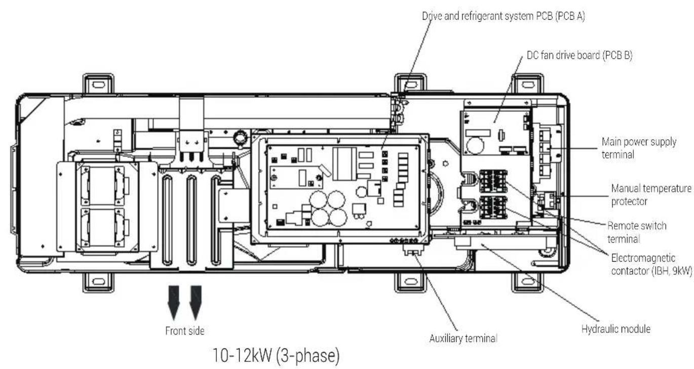
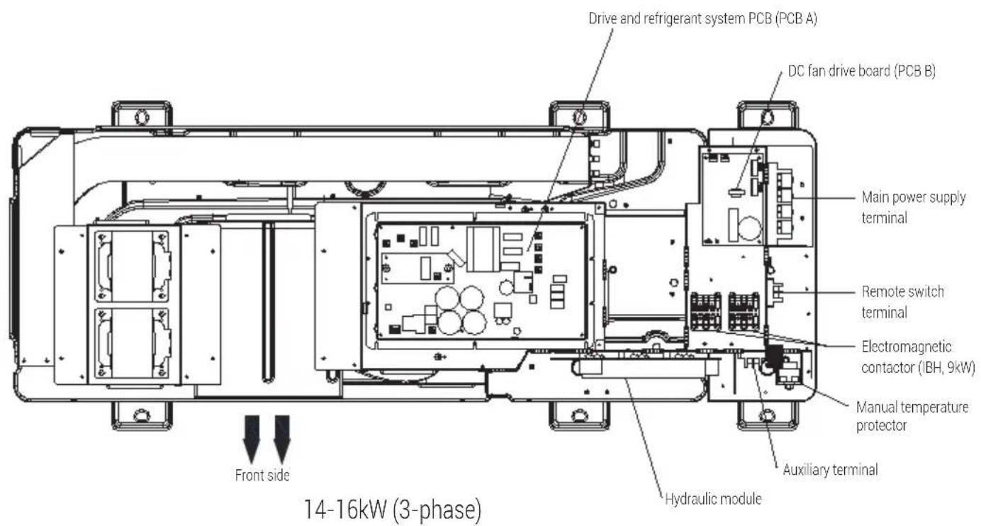
9.3.3 3-phase for 10-16kW units
1) PCB A, 3-phase for 10-16kW, Drive and refrigerant system PCB
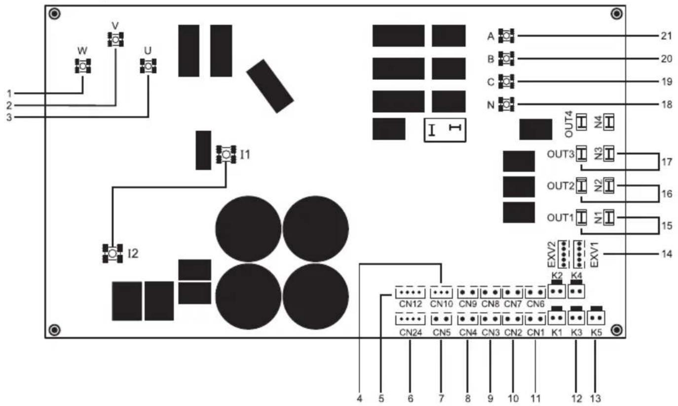
9 Overview of the unit
| Items | Port label | Function Items Port label Function | |||
| 1 | u | E press switch connection port | 12 K3 | Medium pressure switch | |
| 2 v 1 | 3 K5 High pre | Electronic expansion valve | |||
| 3 w 1 | 4 EXV1 | ||||
| 4 | CN10 | Low pressure sensor | 15 | OUT1, N1 | Four way valve |
| 5 CN | 12 | Communication between PCB A and PCB B | 16 | OUT2, N2 | Chassis heater |
| 6 CN | 24 | Communication between PCB A and Main control board of hydraulic module | 17 | OUT3, N3 | Crankcase heater |
| 7 | CN5 Suction temperature | 18 | N | Power supply | |
| 8 | CN4 Discharge temperature | 19 C | |||
| 9 | CN3 EEV Liquid temperature | 20 B | |||
| 10 CN2 Ambient temperature 21 A | |||||
| 11 CN1 Coil temperature | |||||
9 Overview of the unit
2) PCB B, 3-phase for 10-16kW, DC Fan drive board
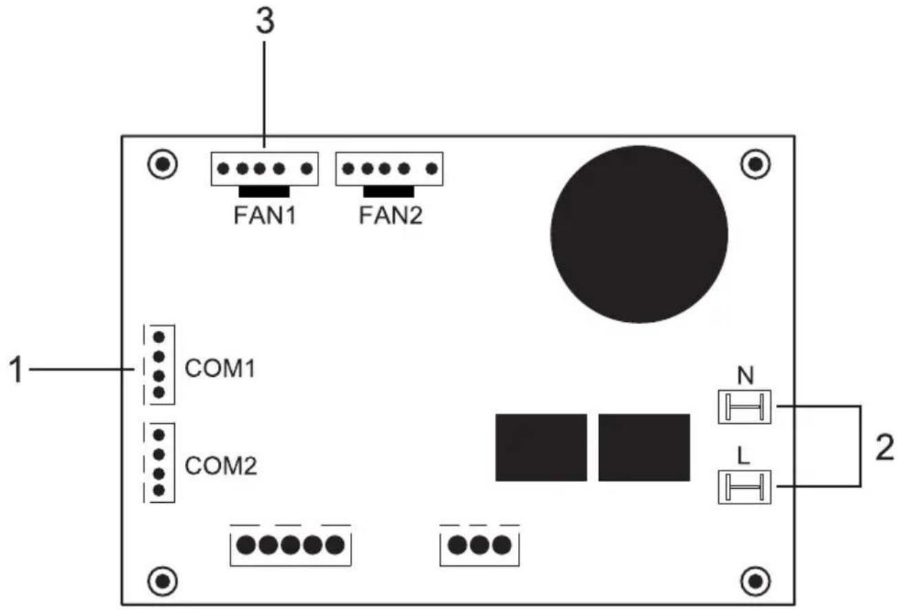
| Items Port label Function | ||
| 1 COM1 | Communication between control PCB A and Fan control board | |
| 2 L, N Power supply | ||
| 3 FAN1 DC FAN | ||
9 Overview of the unit
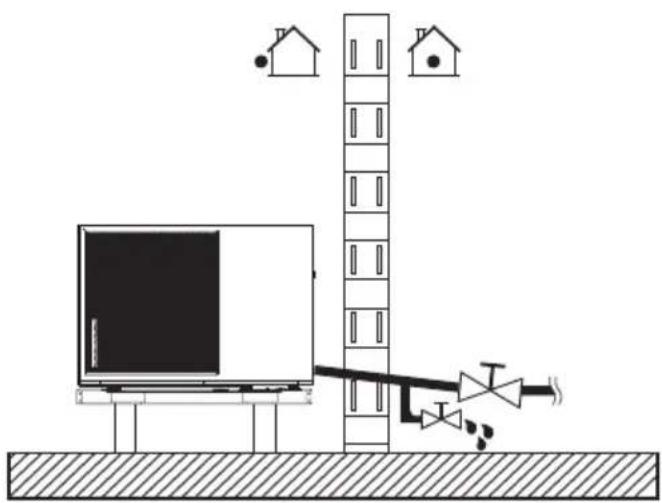
9.4 Water piping
All piping lengths and distances have been taken into consideration.
| Warning: The maximum allowed thermistor cable length is 20m. This is the maximum allowable distance between the domestic hot water tank and the unit (only for installations with a domestic hot water tank). The thermistor cable supplied with the domestic hot water tank is 10m in length. In order to optimize efficiency we recommend installing the 3-way valve and the domestic hot water tank as close as possible to the unit. |
| Note:If the installation is equipped with a domestic hot water tank (field supply), please refer to the domestic hot water tank Installation And Owner's Manual. If there is no glycol (anti-freeze) in the system there is a power supply or pump failure, drain the system (as shown in the figure below). |
natural_image
Diagram of a room with a monitor, ladder, and air flow system (no text or symbols)
Note:
If water is not removed from the system in freezing weather when unit is not used, the frozen water may damage the water circle parts.
9 Overview of the unit
9.4.1 Check the water circuit
The unit is equipped with a water inlet and water outlet for connection to a water circuit. This circuit must be provided by a licensed technician and must comply with local laws and regulations.
The unit is only to be used in a closed water system. Application in an open water circuit can lead to excessive corrosion of the water piping.
Example:
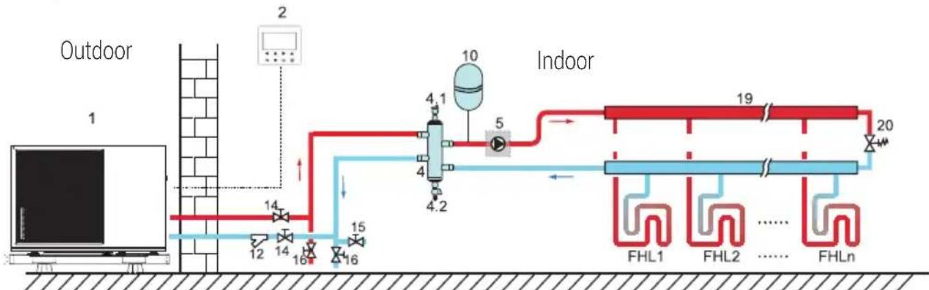
flowchart
graph LR
    A["Outdoor 1"] --> B["12"]
    B --> C["14"]
    C --> D["16"]
    D --> E["15"]
    E --> F["4.2"]
    F --> G["4"]
    G --> H["10"]
    H --> I["Indoor 20"]
    I --> J["19"]
    J --> K["FHL1"]
    J --> L["FHL2"]
    J --> M["FHLn"]
    style A fill:#f9f,stroke:#333
    style I fill:#bbf,stroke:#333
| Code Assembly unit Code Assembly unit | ||
| 1 Main unit 12 Filter (Accessory) | ||
| 2 User interface (accessory) 14 Shut-off valve (Field supply) | ||
| 4 Balance tank (Field supply) 15 Filling valve (Field supply) | ||
| 4.1 Automatic air purge valve 16 Drainage valve (Field supply) | ||
| 4.2 Drainage valve 19 Collector/distributor (Field supply) | ||
| 5 P_o: Outside circulation pump (Field supply) 20 Bypass valve (field supply) | ||
| 10 Expansion vessel (field supply) | FHL1...n | Floor heating loop (Field supply) |
Before continuing installation of the unit, check the following:
• The maximum water pressure ≤ 3 bar.
• The maximum water temperature ≤ 70°C according to safety device setting.
• Always use materials that are compatible with the water used in the system and with the materials used in the unit.
- Ensure that components installed in the field piping can withstand the water pressure and temperature.
9 Overview of the unit
- Drain taps must be provided at all low points of the system to permit complete drainage of the circuit during maintenance.
- Air vents must be provided at all high points of the system. The vents should be located at points that are easily accessible for service. An automatic air purge valve is provided inside the unit. Check that this air purge valve is not tightened so that automatic release of air in the water circuit is possible.
9.4.2 Water volume and sizing expansion vessels
The units are equipped with an expansion vessel of 5L that has a default pre-pressure of 0.15 bar. To assure proper operation of the unit, the pre-pressure of the expansion vessel might need to be adjusted.
1) Check that the total water volume in the installation, excluding the internal water volume of the unit, is at least 40L. See 14 "Technical specifications" to find the total internal water volume of the unit.

Notes:
• In most applications this minimum water volume will be satisfactory.
• In critical processes or in rooms with a high heat load though, extra water might be required.
- When circulation in each space heating loop is controlled by remotely controlled valves, it is important that this minimum water volume is kept even if all the valves are closed.
2) Expansion vessel volume must fit the total water system volume.
3) To size the expansion for the heating and cooling circuit.
The expansion vessel volume can follow the figure below:
9 Overview of the unit
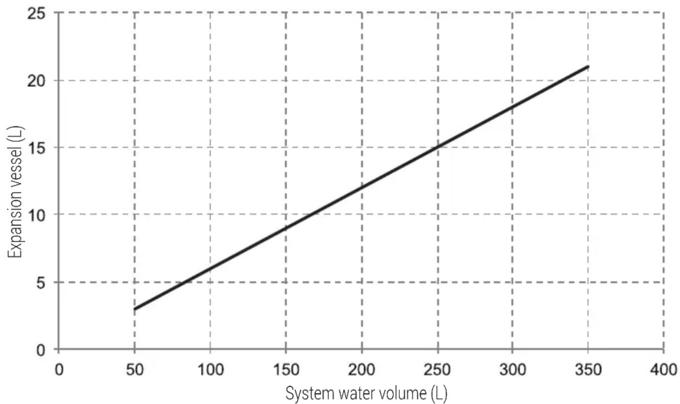
line
| System water volume (L) | Expansion vessel (L) | | ----------------------- | -------------------- | | 50 | 3 | | 100 | 6 | | 150 | 9 | | 200 | 12 | | 250 | 15 | | 300 | 18 | | 350 | 21 |9.4.3 Water circuit connection
Water connections must be made correctly in accordance with labels on the outdoor unit, with respect to the water inlet and water outlet.

Warning:
Be careful not to deform the unit's piping by using excessive force when connecting the piping. Deforming the piping can cause the unit to malfunction.
If air, moisture or dust gets in the water circuit, problems may occur. Therefore, always take into account the following when connecting the water circuit:
• Use clean pipes only.
- Hold the pipe end downwards when removing burrs.
• Cover the pipe end when inserting it through a wall to prevent dust and dirt entering.
- Use a good thread sealant for sealing the connections. The sealing must be able to withstand the pressures and temperatures of the system.
- When using non-copper metallic piping, be sure to insulate two kind of materials from each other to prevent galvanic corrosion.
- For copper is a soft material, use appropriate tools for connecting the water circuit. Inappropriate tools will cause damage to the pipes.
natural_image
Technical line drawing of a mechanical assembly with rollers and shafts (no text or symbols)9 Overview of the unit
Notes:
The unit is only to be used in a closed water system. Application in an open water circuit can lead to excessive corrosion of the water piping:
- Never use Zn-coated parts in the water circuit. Excessive corrosion of these parts may occur as copper piping is used in the unit's internal water circuit.
- When using a 3-way valve in the water circuit. Preferably choose a ball type 3-way valve to guarantee full separation between the domestic hot water and floor heating water circuit.
- When using a 3-way valve or a 2-way valve in the water circuit. The recommended maximum changeover time of the valve should be less than 60 seconds.
9.4.4 Water circuit anti-freeze protection
All internal hydronic parts are insulated to reduce heat loss. Insulation must also be added to the field piping.
In event of a power failure, the above features would not protect the unit from freezing.
The software contains special functions using the heat pump and backup heater (if it is available) to protect the entire system against freezing. When the temperature of the water flow in the system drops to a certain temperature, the unit will heat the water, either using the heat pump, the electric
heating tap, or the backup heater. The freeze protection function will turn off only when the temperature increases to a certain valve.
Water may enter into the flow switch and cannot be drained out and may freeze when the temperature is low enough. The flow switch should be removed and dried, then can be reinstalled in the unit.
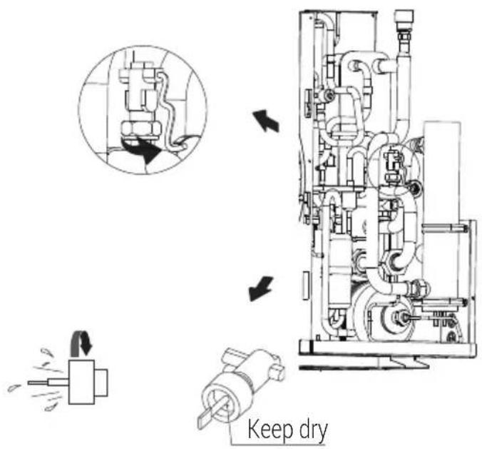

Note:
Counterclock wise rotation, remove the flow switch. Drying the flow switch completely.
9 Overview of the unit

Warning:
When the unit is not running for a long time, make sure the unit is powered on all the time. If you want to cut off the power, the water in the system pipe needs to be drained clean, avoid the unit and pipeline system be damaged by freezing. Also the power of the unit needs to be cut off after water in the system is drained off.

Warning:
Ethylene Glycol and Propylene Glycol are TOXIC
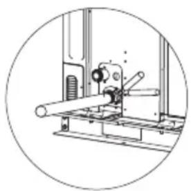
9.5 Filling water
- Connect the water supply to the filling valve and open the valve.
• Make sure the manual air purge valve is open (at least 2 turns). - Fill with water pressure of approximately 2.0 bar. Remove air in the circuit as much as possible using the air purge valves. Air in the water circuit could lead to malfunction of the backup electric heater.
Do not fasten the black plastic cover on the vent valve at the topside of the unit when the system is running. Open air purgevalve, turn anticlockWise at least2 full turnsto releaseair from the system.

natural_image
Technical line drawing of a mechanical assembly with pipes and components (no text or symbols)
Notes:
During filling, it might not be possible to remove all air in the system. Remaining air will be removed through the automatic air purge valves during the first operating hours of the system. Topping up the water afterwards might be required.
- The water pressure will vary depending on the water temperature (higher pressure at higher water temperature). However, at all times water pressure should remain above 0.3 bar to avoid air entering the circuit.
- The unit might drain-off too much water through the pressure relief valve.
• Water quality should be complied with EN 98/83 EC Directives.
• Detailed water quality condition can be found in EN 98/83 EC Directives.
9.6 Water piping insulation
The complete water circuit including all piping, water piping must be insulated to prevent condensation during cooling operation and reduction of the heating and cooling capacity as well as prevention of freezing of the outside water piping during winter. The insulation material should at least of B1 fire resistance rating and complies with all applicable legislation. The thickness of the sealing materials must be at least 13 mm with thermal conductivity 0.039 W/mK in order to prevent freezing on the outside water piping.
If the outdoor ambient temperature is higher than 30^ C and the humidity is higher than RH 80%, then the thickness of the sealing materials should be at least 20 mm in order to avoid condensation on the surface of the seal.
9.7 Field wiring
Warning:
A main switch or other means of disconnection, having a contact separation in all poles, must be incorporated in the fixed wiring in accordance with relevant local laws and regulations. Switch off the power supply before making any connections. Use only copper wires. Never squeeze bundled cables and make sure they do not come in contact with the piping and sharp edges. Make sure no external pressure is applied to the terminal connections. All field wiring and components must be installed by a licensed electrician and must comply with relevant local laws and regulations.
The field wiring must be carried out in accordance with the wiring diagram supplied with the unit and the instructions given below.
Be sure to use a dedicated power supply. Never use a power supply shared by another appliance.
Be sure to establish a ground. Do not ground the unit to a utility pipe, surge protector, or telephone ground. Incomplete grounding may cause electrical shock.
Be sure to install a ground fault circuit interrupter (30 mA). Failure to do so may cause electrical shock. Be sure to install the required fuses or circuit breakers.
9.7.1 Precautions on electrical wiring work
- Fix cables so that cables do not make contact with the pipes (especially on the high pressure side).
- Secure the electrical wiring with cable ties as shown in figure so that it does not come in contact with the piping, particularly on the high-pressure side.
• Make sure no external pressure is applied to the terminal connectors. - When installing the ground fault circuit interrupter make sure that it is compatible with the inverter (resistant to high frequency electrical noise) to avoid unnecessary opening of the ground fault circuit interrupter.

Note:
The ground fault circuit interrupter must be a high-speed type breaker of 30 mA (<0.1 s).
- This unit is equipped with an inverter. Installing a phase advancing capacitor not only will reduce the power factor improvement effect, but also may cause abnormal heating of the capacitor due to high-frequency waves. Never install a phase advancing capacitor as it could lead to an accident.

9 Overview of the unit
9.7.2 Wiring overview
The illustration below gives an overview of the required field wiring between several parts of the installation.

Note:
Please use H07RN-F for the power wire, all the cable are connect to high voltage except for thermistor cable and cable for user interface.
• Equipment must be grounded.
- All high-voltage external load, if it is metal or a grounded port, must be grounded.
- All external load current is needed less than 0.2A, if the single load current is greater than 0.2A, the load must be controlled through AC contactor.
- AHS1" "AHS2", "A1" "A2", wiring terminal ports provide only the switch signal. Please refer to image of 9.7.6 to get the ports position in the unit.
Figure 3-4.2.1: Wiring hole for 4/6/8kW models
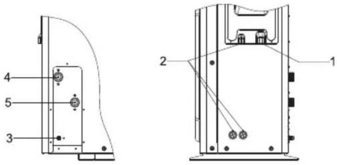
Figure 3-4.2.2: Wiring hole for 10/12kW models
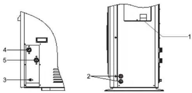
Figure 3-4.2.3: Wiring hole for 14/16kW models
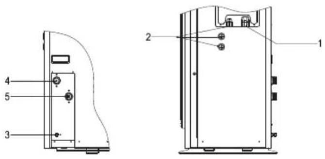
Code Assembly unit
1 High voltage wire hole
2 Low voltage wire hole
3 Drainage pipe hole
4 Water outlet
5 Water inlet
Field wiring guidelines
- Most field wiring on the unit is to be made on the terminal block inside the switch box. To gain access to the terminal block, remove the switch box service panel (door 1).

Warning:
Switch off all power including the unit power supply and backup heater and domestic hot water tank power supply (if applicable) before removing the switch box service panel.
9 Overview of the unit
• Fix all cables using cable ties.
- A dedicated power circuit is required for the backup heater.
- Installations equipped with a domestic hot water tank (field supply) require a dedicated power circuit for the booster heater. Please refer to the domestic hot water tank Installation & Owner's Manual. Secure the wiring in the order shown below.
- Lay out the electrical wiring so that the front cover does not rise up when doing wiring work and attach the front cover securely.
- Follow the electric wiring diagram for electrical wiring works (the electric wiring diagrams are located on the rear side of door 2.
• Install the wires and fix the cover firmly so that the cover may be fit in properly.
9.7.3 Precautions on wiring of power supply
- Use a round crimp-style terminal for connection to the power supply terminal board. In case it cannot be used due to unavoidable reasons, be sure to observe the following instructions.
- Do not connect different gauge wires to the same power supply terminal. (Loose connections may cause overheating.)
- When connecting wires of the same gauge, connect them according to the figure below.
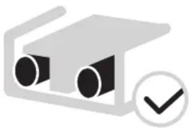
natural_image
Simple icon of two cylindrical objects inside a rectangular frame with a checkmark (no text or symbols)
natural_image
Simple diagram of a device with three cylindrical components and a cross symbol (no text or labels)
natural_image
Simple diagram of a device with two circular components and a cross symbol (no text or labels)- Use the correct screwdriver to tighten the terminal screws. Small screwdrivers can damage the screw head and prevent appropriate tightening.
• Over-tightening the terminal screws can damage the screws. - Attach a ground fault circuit interrupter and fuse to the power supply line.
- In wiring, make certain that prescribed wires are used, carry out complete connections, and fix the wires so that outside force cannot affect the terminals.
9.7.4 Safety device requirement
- Select the wire diameters (minimum valve) individually for each unit based on the table 9-1 and table 9-2, where the rated current in table 9-1 means MCA in table 9-2. In case the MCA exceeds 63A, the wire diameters should be selected according to the national wiring regulation.
- Maximum allowable voltage range variation between phases is 2%.
- Select circuit breaker that having a contact separation in all poles not less than 3 mm providing full disconnection, where MFA is used to select the current circuit breakers and residual current operation breakers.
9 Overview of the unit
1-phase 4-16kW standard and 3-phase 10-16kW standard
| System | Outdoor Unit Power Current Compressor OFM | ||||||||||
| Voltage (V) | Hz | Min. (V) | Max. (V) | MCA (A) | TOCA (A) | MFA (A) | MSC (A) | RLA (A) KW FLA (A) | |||
| 4kW 220-240~50 | 198 26 | 4 12 | 18 25 - | 11.50 | 0.10 | 0.50 | |||||
| 6kW 220-240~50 | 198 26 | 4 14 | 18 25 - | 13.50 | 0.10 | 0.50 | |||||
| 8kW 220-240~50 | 198 26 | 4 16 | 19 25 - | 14.50 | 0.17 | 1.50 | |||||
| 10kW 220-240~50 | 198 26 | 4 19 | 23 25 - | 15.50 | 0.17 | 1.50 | |||||
| 12kW 220-240~50 | 198 26 | 4 26 | 30 35 - | 23.50 | 0.17 | 1.50 | |||||
| 14kW 220-240~50 | 198 26 | 4 27 | 30 35 - | 24.50 | 0.17 | 1.50 | |||||
| 16kW 220-240~50 | 198 26 | 4 27 | 30 35 - | 25.50 | 0.17 | 1.50 | |||||
| 10kW 3-PH | 380-415~ | 50 | 342 | 456 | 6 | 11 | 16 | - | 5.15 | 0.17 | 1.50 |
| 12kW 3-PH | 380-415~ | 50 | 342 | 456 | 10 | 14 | 16 | - | 9.15 | 0.17 | 1.50 |
| 14kW 3-PH | 380-415~ | 50 342 | 456 1 | 2 14 16 | - 10.15 | 0.17 | 1.50 | ||||
| 16kW 3-PH | 380-415~ | 50 342 | 456 1 | 2 14 16 | - 11.15 | 0.17 | 1.50 | ||||
1-phase 4-16kW standard with backup heater 3kW
| System | Outdoor Unit | Power Current Compressor OFM | |||||||||
| Voltage (V) | Hz | Min. (V) | Max. (V) | MCA (A) | TOCA (A) | MFA (A) | MSC (A) | RLA (A) | KW | FLA (A) | |
| 4kW | 220-240~ | 50 | 198 | 264 | 25 | 31 | 38 | - | 11.50 | 0.10 | 0.50 |
| 6kW | 220-240~ | 50 | 198 | 264 | 27 | 31 | 38 | - | 13.50 | 0.10 | 0.50 |
| 8kW | 220-240~ | 50 | 198 | 264 | 29 | 32 | 38 | - | 14.50 | 0.17 | 1.50 |
| 10kW | 220-240~ | 50 | 198 | 264 | 32 | 36 | 38 | - | 15.50 | 0.17 | 1.50 |
| 12kW | 220-240~ | 50 | 198 | 264 | 39 | 43 | 48 | - | 23.50 | 0.17 | 1.50 |
| 14kW | 220-240~ | 50 | 198 | 264 | 40 | 43 | 48 | - | 24.50 | 0.17 | 1.50 |
| 16kW | 220-240~ | 50 | 198 | 264 | 40 | 43 | 48 | - | 25.50 | 0.17 | 1.50 |
9 Overview of the unit
3-phase 10-16kW standard with backup heater 9kW
| System | Outdoor Unit Power Current Compressor OFM | ||||||||||
| Voltage (V) | Hz | Min. (V) | Max. (V) | MCA (A) | TOCA (A) | MFA (A) | MSC (A) | RLA (A) | KW FLA (A) | ||
| 10kW 3 | 80-415~50 | 342 456 20 | 25 30 - 5 | .15 0.1 | 7 1.50 | ||||||
| 12kW 3 | 80-415~50 | 342 456 24 | 28 30 - 9 | .15 0.1 | 7 1.50 | ||||||
| 14kW 3 | 80-415~50 | 342 456 25 | 28 30 - 1 | 0.15 | 0.17 1.50 | ||||||
| 16kW 3 | 80-415~50 | 342 456 26 | 28 30 - 1 | 1.15 | 0.17 1.50 | ||||||

Notes:
MCA: Max. Circuit Amps. (A)
TOCA: Total Over-current Amps. (A)
MFA: Max. Fuse Amps. (A)
MSC: Max. Starting Amps. (A)
RLA: In nominal cooling or heating test condition, the input Amps of compressor where MAX. Hz can operate Rated Load Amps. (A)
KW: Rated Motor Output
FLA: Full Load Amps. (A)
9 Overview of the unit
9.7.5 Remove the switch box cover
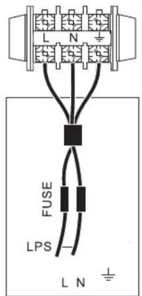
UNIT POWER SUPPLY 1-phase
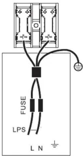
UNIT POWER SUPPLY 1-phase
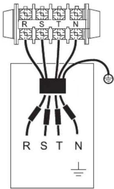
UNIT POWER SUPPLY 3-phase

Notes:
The ground fault circuit interrupter must be 1 high-speed type of 30mA (<0.1s). Please use 3-core shielded wire.
The default of backup heater is option 3 (for 9kW backup heater).
Stated values are maximum values (see electrical data for exact values).
When connecting to the power supply terminal, use the circular wiring terminal with the insulation casing (see Figure 9.1).
Use power cord that conforms to the specifications and connect the power cord firmly. To prevent the cord from being pulled out by external force, make sure it is fixed securely.
If circular wiring terminal with the insulation casing cannot be used, please make sure that:
- Do not connect two power cords with different diameters to the same power supply terminal (may cause overheating of wires due to loose wiring) (See Figure 9.2).
9 Overview of the unit
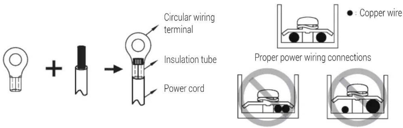
9.7.6 Connection for other components
unit 4-16kW
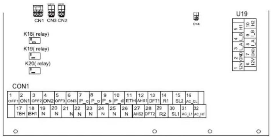
| CON I | Code | Canned to | ||
| 1 | 1 | OFF1 | SV1 (5-way valve) | |
| 2 | ON1 | |||
| 19 | N | |||
| 2 | 3 | OFF2 | SV2 (5-way valve) | |
| 4 | ON2 | |||
| 20 | N | |||
| 3 | 5 | OFF3 | SV3 (5-way valve) | |
| 6 | ON3 | |||
| 21 | N | |||
| 4 | 7 | P, c | Pumpc (zoneD pump) | |
| 22 | N | |||
| 5 | 8 | P, o | Outside circulation on pump of zoneI pump | |
| 23 | N | |||
| 6 | 9 | P, s | Solar energy pump | |
| 24 | N | |||
| 7 | 10 | P, d | DHIT pipe pump | |
| 25 | N | |||
| 8 | 11 | ETH | Reserved | |
| 26 | N | |||
| 9 | 12 | AH51 | Additional heat source | |
| 27 | AH52 | |||
| 10 | 13 | OFF1 | Reserved | |
| 28 | OFF2 | |||
| 11 | 14 | R, t | Reserved | |
| 29 | R, 2 | |||
| 12 | 15 | SL7 | Solar energy input signal | |
| 30 | SL1 | |||
| 13 | 16 | AC, CL | Roan/thermostat input (high voltage) | |
| 31 | AC, L1 | |||
| 32 | AC, HT | |||
| Code | Converted to | ||
| 1 | CL |
Port provide the control signal to the load. Two kind of control signal port:
Type 1: Dry connector without voltage.
Type 2: Port provide the signal with 220V voltage. If the current of load is <0.2A, load can connect to the port directly. If the current of load is >=0.2A, the AC contactor is required to connected for the load.
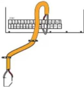
natural_image
Diagram of a yellow cable or pipe connecting a grid structure with a hook, no text or symbols presentType 1 For additional heat source control
9 Overview of the unit
| Voltage 220-240~VACMaximum running current (A) 0.2Wiring size (mm ^2 ) 0.75 |
2) For 3-way valve SV1, SV2 and SV3:
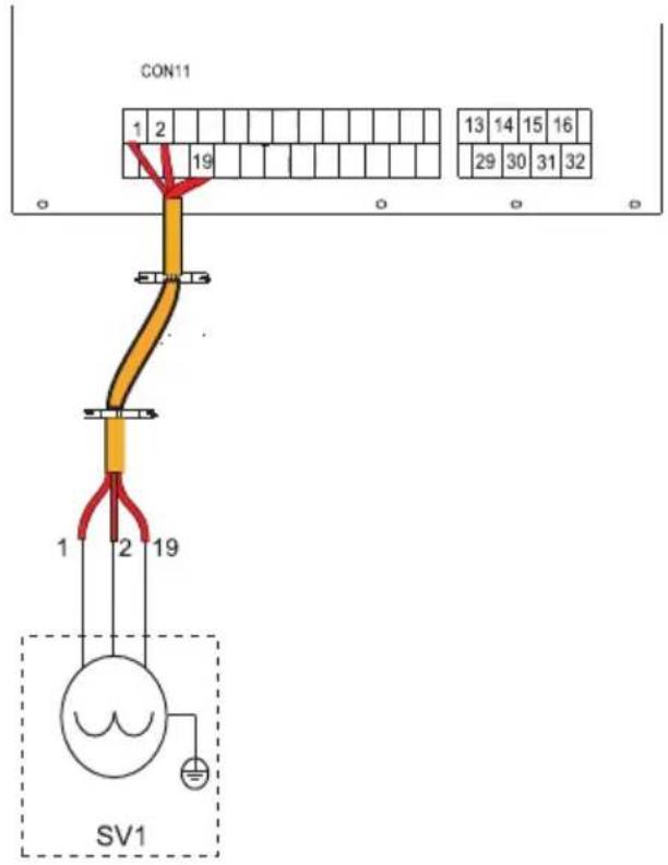
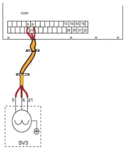
| Voltage 220-240~VACMaximum running current (A) 0.2Wiring size ( mm^2 ) 0.75Control port signal type Type 2 |
a) Procedure
- Connect the cable to the appropriate terminals as shown in the picture.
- Fix the cable reliably.
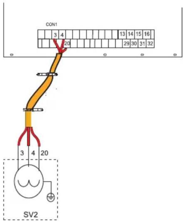
9 Overview of the unit
3) For remote shut down:
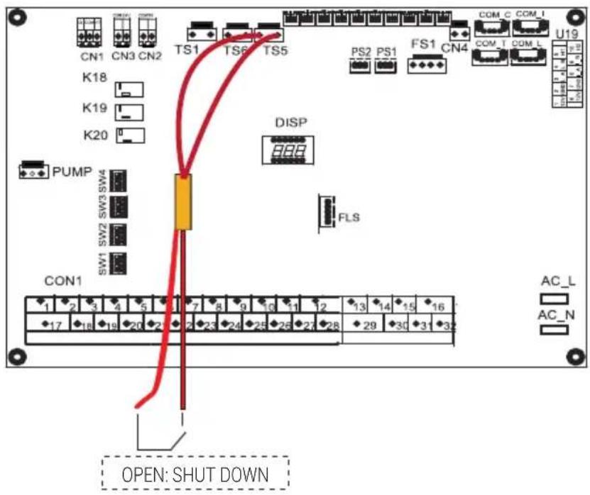
9 Overview of the unit
4) For Pumpc and DHW pipe pump:
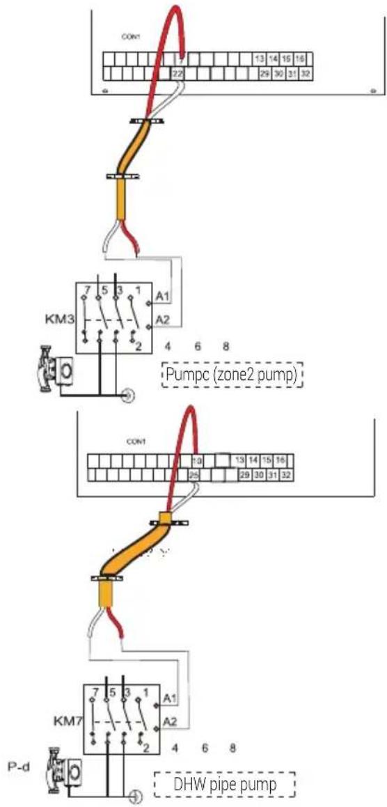
| Voltage 220-240~VACMaximum running current (A) 0.2Wiring size (mm2) 0.75Control port signal type Type 2 |
a) Procedure
- Connect the cable to the appropriate terminals as shown in the picture.
- Fix the cable reliably.
5) For room thermostat:
Room thermostat type 1 (High voltage):
"POWER IN" provide the working voltage to the RT, doesn't provide the voltage to the RT connector directly. Port "31 L1" provide the 220V voltage to the RT connector. Port "31 L1" connect from the unit main power supply port L of 1- phase power supply.
Room thermostat type 2 (Low voltage):
"POWER IN" provide the working voltage to the RT.

Note:
There are two optional connect method depend on the room thermostat type.
Room thermostat type 1 (High voltage):
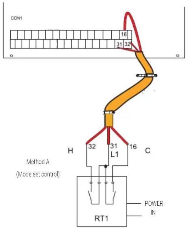
9 Overview of the unit
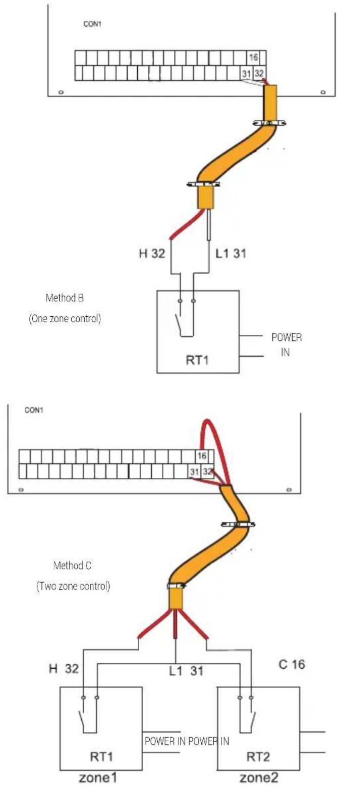
flowchart
graph TD
    subgraph_Method_B["Method B\n(One zone control)"]
        A["CON1"] --> B["H 32"]
        B --> C["L1 31"]
        C --> D["RT1"]
        D --> E["POWER IN"]
    end
    subgraph_Method_C["Method C\n(Two zone control)"]
        F["CON1"] --> G["H 32"]
        G --> H["L1 31"]
        H --> I["RT1"]
        I --> J["POWER IN POWER IN"]
        J --> K["C 16"]
        K --> L["RT2"]
        L --> M["zone1"]
        L --> N["zone2"]
    end
| Voltage 220-240~VAC | |
| Maximum running current (A) 0.2 | |
| Wiring size (mm ^2 ) 0.75 |
There are three methods for connecting the thermostat cable (as described in the picture above) and it depends on the application.
• Method A (Mode set control)
RT can control heating and cooling individually, like the controller for 4-pipe FCU. When the hydraulic module is connected with the external temperature controller, user interface set ROOM THERMOSTAT to MODE SET:
A.1 When unit detect voltage is 230VAC between C and L1, the unit operates in the cooling mode.
A.2 When unit detect voltage is 230VAC between H and L1, the unit operates in the heating mode.
A.3 When unit detect voltage is 0VAC for both side (C-L1, H-L1) the unit stop working for space heating or cooling.
A.4 When unit detect voltage is 230VAC for both side (C-L1, H-L1) the unit working in cooling mode.
• Method B (One zone control)
RT provide the switch signal to unit. User interface set ROOM THERMOSTAT to ONE ZONE:
B.1 When unit detect voltage is 230VAC between H and L1, unit turns on.
B.2 When unit detect voltage is 0VAC between H and L1, unit turns off.
9 Overview of the unit
• Method C (Two zone control)
Hydraulic Module is connected with two room thermostat, while user interface set ROOM THERMOSTAT to ZONES:
C.1 When unit detect voltage is 230VAC between H and L1, zone1 turns on. When unit detect voltage is 0VAC between H and L1, zone1 turns off.
C.2 When unit detect voltage is 230VAC between C and L1, zone2 turns on according to climate temp curve. When unit detect voltage is 0V between C and L1, zone2 turns off.
C.3 When H-L1 and C-L1 are detected as OVAC, unit turns off.
C.4 When H-L1 and C-L1 are detected as 230VAC, both zone1 and zone2 turn on.
Room thermostat type 2 (Low voltage):
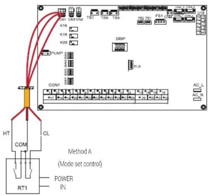
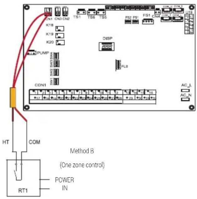
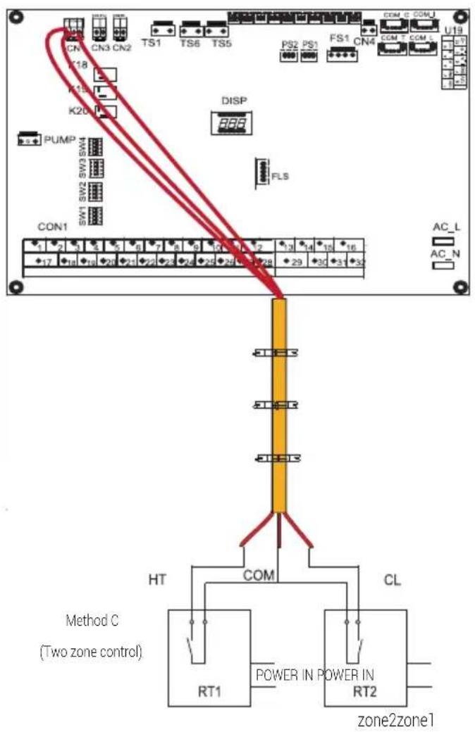
9 Overview of the unit
There are three methods for connecting the thermostat cable (as described in the picture above) and it depends on the application.
• Method A (Mode set control)
RT can control heating and cooling individually, like the control- ler for 4-pipe FCU. When the hydraulic module is connected with the external temperature controller, user interface set ROOM THERMOSTAT to MODE SET:
A.1 When unit detect voltage is 12VDC between CL and COM, the unit operates in the cooling mode.
A.2 When unit detect voltage is 12VDC between HT and COM, the unit operates in the heating mode.
A.3 When unit detect voltage is OVDC for both side (CL-COM, HT-COM) the unit stop working for space heating or cooling.
A.4 When unit detect voltage is 12VDC for both side (CL-COM, HT-COM) the unit working in cooling mode.
• Method B (One zone control)
RT provide the switch signal to unit. User interface set ROOM THERMOSTAT to ONE ZONE:
B.1 When unit detect voltage is 12VDC between HT and COM, unit turns on.
B.2 When unit detect voltage is OVDC between HT and COM, unit turns off.
• Method C (Two zone control)
Hydraulic Module is connected with two room thermostat, while user interface set ROOM THERMOSTAT to ZONES:
C.1 When unit detect voltage is 12VDC between HT and COM, zone 1 turn on. When unit detect voltage is 0VDC between HT and COM, zone1 turn off.
C.2 When unit detect voltage is 12VDC between CL and COM, zone2 turn on according to climate temp curve. When unit detect voltage is 0V between CL and COM, zone2 turn off.
C.3 When HT-COM and CL-COM are detected as OVDC, unit turn off.
C.4 When HT-COM and CL-COM are detected as 12VDC, both zone1 and zone2 turn on.
Notes:
The wiring of the thermostat should correspond to the settings of the user interface.
Power supply of machine and room thermostat must be connected to the same Neutral Line.
Zone 2 can only operate in heating mode, When cooling mode is set on user interface and zone1 is OFF, "CL" in zone 2 closes, system still keeps 'OFF'. While installation, the wiring of thermostats for zone1 and zone 2 must be correct.

9 Overview of the unit
6) For additional heat source control:
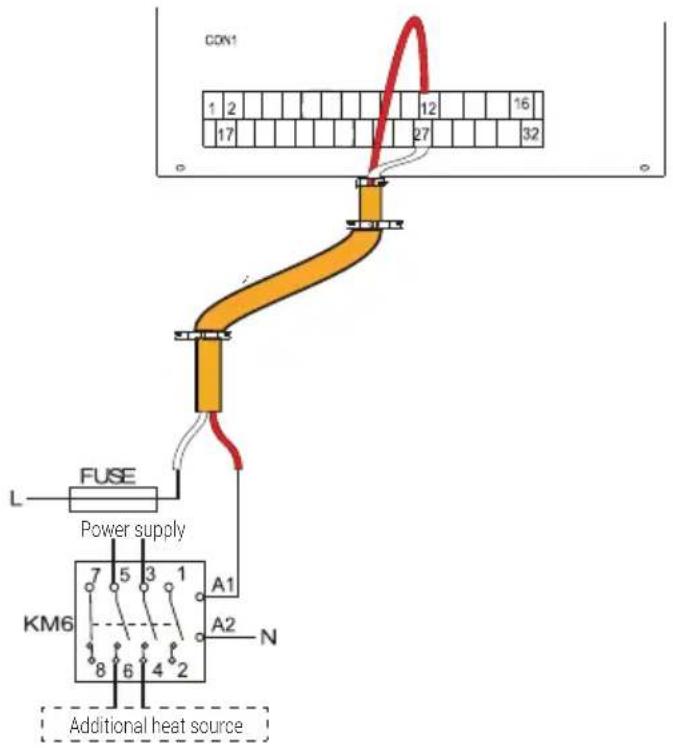
| Voltage 220-240~VACMaximum running current (A) 0.2Wiring size ( mm^2 ) 0.75Control port signal type Type 2 |

Warning:
This part only applies to the unit without an interval backup heater. If there is an interval backup heater in the unit, the hydraulic module should not be connected to any additional heat source.
| Voltage 220-240~VAC | |
| Maximum running current (A) 0.2 | |
| Wiring size (mm ^2 ) 0.75 | |
| Control port signal type Type 1 |
7) For outside circulation pump P_o:

| Voltage 220-240~VACMaximum running current (A) 0.2Wiring size ( mm^2 ) 0.75Control port signal type Type 2 |
a) Procedure
- Connect the cable to the appropriate terminals as shown in the picture.
- Fix the cable with cable ties to the cable tie mountings to ensure stress relief.
9 Overview of the unit
8) For smart grid:
The unit has smart grid function, there are two ports on PCB to connect SG signal and EVU signal as following:
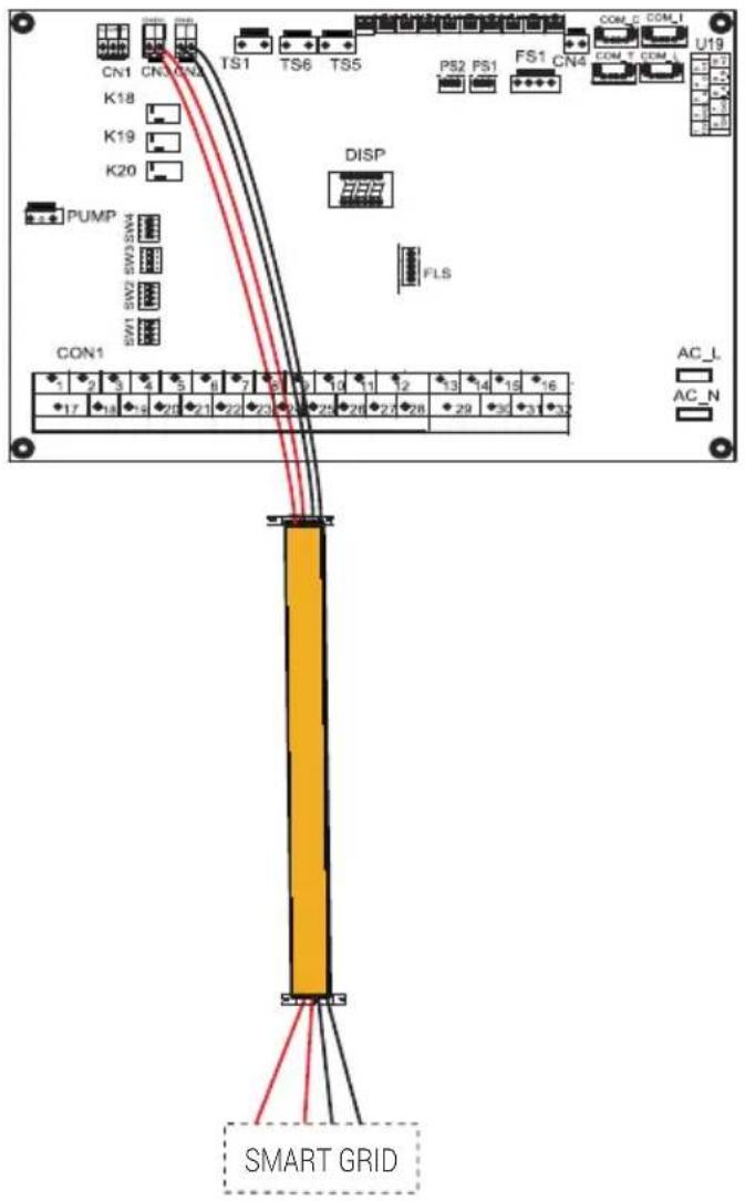
- when EVU signal is on, the unit operate as below:
DHW mode turn on, the setting temperature will be changed to 70^ C automatically, and the WTH operate as below: TW < 69^ C, the WTH is on, TW ≥ 70^ C, the WTH is off. The unit operate in cooling/heating mode as the normal logic.
-
When EVU signal is off, and SG signal is on, the unit operate normally.
-
When EVU signal is off, SG signal is off, the DHW mode is off, and the WTH is invalid, disinfect function is invalid. The max running time for cooling/heating is "SG RUNNIN TIME", then unit will be off.
10 Start-up and configuration
The unit should be configured by the installer to match the installation environment (outdoor climate, installed options, etc.) and user expertise.

Warning:
It is important that all information in this chapter is read sequentially by the installer and that the system is configured as applicable.
10.1 DIP switch settings overview
10.1.1 Function setting
DIP switch SW1, SW2 SW3 and SW4 are located on the main control hydraulic module board (see "9.3.1 main control board of hydraulic module").

Warning:
Switch off the power supply before making any changes to the DIP switch settings.
Refer to eletrically controlled wiring diagram
10.2 Initial start-up at low outdoor ambient temperature
During initial start-up and when water temperature is low, it is important that the water is heated gradually. Failure to do so may result in concrete floors cracking due to rapid temperature change. Please contact the responsible cast concrete building contractor for further details.
10.3 Pre-operationchecks
Checks before initial start-up.

Warning:
Switch off the power supply before making any connections.
After the installation of the unit, check the following before switching on the circuit breaker:
- Field wiring: Make sure that the field wiring between the local supply panel and unit and valves (when applicable), unit and room thermostat (when applicable), unit and domestic hot water tank, and unit and backup heater kit have been connected according to the instructions described in the chapter 9.7 "Field wiring", according to the wiring diagrams and to local laws and regulations.
- Fuses, circuit breakers, or protection devices Check that the fuses or the locally installed protection devices are of the size and type specified in 14 "Technical specifications". Make sure that no fuses or protection devices have been bypassed.
- Backup heater circuit breaker: Do not forget to turn on the backup heater circuit breaker in the switchbox (it depends on the backup heater type). Refer to the wiring diagram.
- Booster heater circuit breaker: Do not forget to turn on the booster heater circuit breaker (applies only to units with optional domestic hot water tank installed).
- Ground wiring: Make sure that the ground wires have been connected properly and that the ground terminals are tightened.
- Internal wiring: Visually check the switch box for loose connections or damaged electrical components.
- Mounting: Check that the unit is properly mounted, to avoid abnormal noises and vibrations when starting up the unit.
- Damaged equipment: Check the inside of the unit for damaged components or squeezed pipes.
- Refrigerant leak: Check the inside of the unit for refrigerant leakage. If there is a refrigerant leak, call your local dealer.
• Power supply voltage: Check the power supply voltage on the local supply panel. The voltage must correspond to the voltage on the identification label of the unit.
• Air purge valve: Make sure the air purge valve is open (at least 2 turns). - Shut-off valves: Make sure that the shut-off valves are fully open.
10 Start-up and configuration
10.4 The circulation pump
The relationships between the head and the water flow rated, the PMW Return and the water flow rated are shown in the graph below.
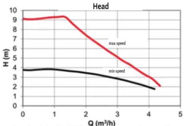
line
| Q (m³/h) | max speed | min speed | | -------- | --------- | --------- | | 0 | 9.0 | 3.8 | | 1 | 9.2 | 3.9 | | 2 | 7.5 | 3.6 | | 3 | 5.5 | 3.0 | | 4 | 3.0 | 1.8 | | 4.5 | 2.0 | 1.5 |Area of regulation is included in between the max speed curve and the min speed curve.
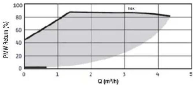
line
| Q (m³/h) | PMW Return (%) | | -------- | -------------- | | 0 | 0 | | 1 | 80 | | 2 | 90 | | 3 | 90 | | 4 | 85 | | 5 | 80 |
Warning:
If the valves are at the incorrect position, the circulation pump will be damaged.

Warning:
If it's necessary to check the running status of the pump when unit power on, please do not touch the internal electronic control box components to avoid electric shock.
Failure diagnosis at first installation
- If nothing is displayed on the user interface, it is necessary to check for any of the following abnormalities before diagnosing possible error codes.
- Disconnection or wiring error (between power supply and unit and between unit and user interface).
- The fuse on the PCB may be broken.
- If the user interface shows "P01" as an error code, there is a possibility that there is air in the system, or the water level in the system is less than the required minimum.
- If the error code E01 is displayed on the user interface, check the wiring between the user interface and unit.
More error code and failure causes can be found in 13.4 "Error codes".
10.5 Field settings
The unit should be configured to match the installation environment (outdoor climate, installed options, etc.) and user demand. A number of field settings are available. These settings are accessible and programmable through "FUNCTION PARAMETER SET" in user interface.
Procedure
To change one or more field settings, proceed as follows.

Note:
Temperature values displayed on the wired controller (user interface) are in °C.
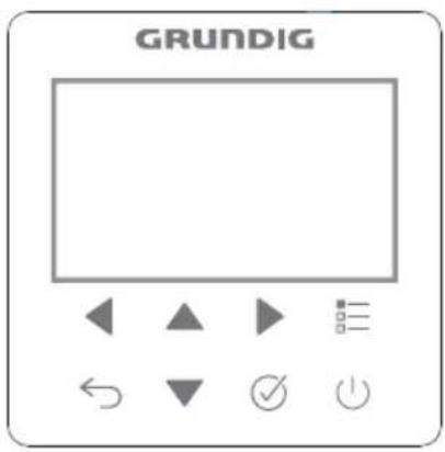
| Keys Function | |
 | Go to the menu structure (on the home page) |
 | Navigate the cursor on the displayNavigate in the menu structureAdjust settings |
 | Turn on/off the space heating/cooling operation or DHW modeTurn on/or off functions in the menu structure |
 | Come back to the up level |
 | Go to the next step when programming a schedule in the menu structure; and confirm a selection to enter in the submenu of the menu structure. |
About FUNCTION PARAMETER SET
"FUNCTION PARAMETER SET" is designed for the installer to set the parameters.
- Setting the composition of equipment.
- Setting the parameters.
How to go to FUNCTION PARAMETER SET
Go to ➞ FUNCTION PARAMETER SET. Press : √
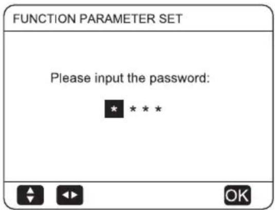
Press ◀▶ to navigate and press ▼▲ to adjust the numerical valve. Press ☑The password is 1212, the following pages will be displayed after putting the password:
10 Start-up and configuration
| FUNCTION PARAMETER SET 1/2 | |
| 1. GENERAL PARAMETER | |
| 2.DHW MODE Set | |
| 3. HEAT MODE Set | |
| 4. COOL MODE Set | |
| 5. AUTO MODE Set | |
| FUNCTION PARAMETER SET 2/2 | |
| 6. TEMP. TYPE SET | |
| 7. ROOM THERMOSTAT SET | |
| 8. OTHER HEAT SOURCE | |
| 9. AUTO RESTART | |
| 10. RESTORE FACTORY Set | |
Press ▼ ▲ to scroll and use "OK" to enter submenu.
10.5.1 GENERAL PARAMETER
Go to > FUNCTION PARAMETER SET>
- GENERAL PARAMETER. Press ☑The following pages will be displayed:
| 1 GENERAL PARAMETER | 1/5 |
| 1.1 Ta | 2°C |
| 1.2 Mp | 0 |
| 1.3 T4L | -25°C |
| 1.4 PUMP_TYPE | DC |
| 1.5 SB-PWMout | 35% |
| OK |
| 1 GENERAL PARAMETER | 2/5 |
| 1.6 RUN-PWMout | 45% |
| 1.7 IP | 251 |
| 1.8 TH4 | 1 |
| 1.9 a | 3°C |
| 1.10 WPS | 1 |
| OK |
| 1 GENERAL PARAMETER | 3/5 |
| 1.11 TE1 | NON |
| 1.12 TE2 | NON |
| 1.13 TZ2 | NON |
| 1.14 SMART GRID | NON |
| 1.15 dTE | 15°C |
| OK |
| 1 GENERAL PARAMETER | 4/5 |
| 1.16 t_SV3_ON | 5MIN |
| 1.17 t_SV3_OFF | 2MIN |
| 1.18 dT_SV3_ON | 5°C |
| 1.19 dT_SV3_OFF | 0°C |
| 1.20 dTro | 1.0°C |
| OK |
| 1 GENERAL PARAMETER | 5/5 |
| 1.21 Tro-adj | 0°C |
DHW = domestic hot water
Go to ➞ FUNCTION PARAMETER SET> 2. DHW MODE. Press ⚙The following pages will be displayed
| 2 DHW MODE | 1/3 |
| 2.1 Tb | 5°C |
| 2.2 Tx | 65°C |
| 2.3 Td | 30MIN |
| 2.4 Teh | 4°C |
| 2.5 P_d_DHW | NON |
| OK |
10 Start-up and configuration
| 2 DHW MODE | 2/3 |
| 2.6 P_d_DIS | YES |
| 2.7 P d TIME KEEP | YES |
| 2.8 t_P_d_ON | 15MIN |
| 2.9 t P d OFF | 120MIN |
| 2.10 P_d_AUTO | YES |
| OK |
| 3 HEAT MODE | 4/4 |
| 3.16 SPTch_set2 | 28°C |
10.5.3 HEAT MODE SETTING
Go to ➕ FUNCTION PARAMETER SET> 3. HEAT MODE. Press ⚙The following pages will be displayed
| 3 HEAT MODE | 1/4 |
| 3.1 HEAT TEMP. AUTO ADJUST | 0 |
| 3.2 Hi_A | 5°C |
| 3.3 Lo_A | 0°C |
| 3.4 A | 5°C |
| 3.5 HIGH TEMP HEAT OFF | 0 |
| OK |
| 3 HEAT MODE | 2/4 |
| 3.6 T4h | 24°C |
| 3.7 H-PUMP | 3 |
| 3.8 HD | 1 |
| 3.9 T4g | -10°C |
| 3.10 ZONE A HEAT-TYPE | RAD |
| OK |
10.5.4 COOL MODE SETTING
Go to ➞ FUNCTION PARAMETER SET> 4. COOL MODE. Press ☑The following pages will be displayed
| 4 COOL MODE | 1/2 |
| 4.1 C-Pump | 3 |
| 4.2 ZONE A COOL -TYPE | FCU |
| 4.3 ZONE B COOL -TYPE | FCU |
| 4.4 t_T4_FRESH_C | 30MIN |
| 4.5 T4_ca1 | 25°C |
| OK |
| 4 COOL MODE | 2/2 |
| 4.6 T4_ca2 | 35°C |
| 4.7 SPTcc set1 | 16°C |
| 4.8 SPTcc set2 | 10°C |
10 Start-up and configuration
10.5.5 AUTO MODE SETTING
Go to ➕ FUNCTION PARAMETER SET> 5. AUTO MODE. Press ☑The following pages will be displayed
| 5 AUTO MODE | 1/1 |
| 5.1 AUTO HEAT MAX T4 | 17°C |
| 5.2 AUTO COOL MIN T4 | 25°C |
10.5.6 TEMP. TYPE SETTING
About TEMP. TYPE SETTING
The TEMP. TYPE SETTING is used for selecting whether the water flow temperature or room temperature is used to control the ON/OFF of the heat pump.
When ROOM TEMP. is enabled, the target water flow temperature will be calculated from climate-related curves.
Go to > FUNCTION PARAMETER SET >
- TEMP. TYPE SET. Press ✅ The following pages will be displayed
10.5.7 ROOM THERMOSTAT
About ROOM THERMOSTAT
The ROOM THERMOSTAT is used to set whether the room thermostat is available.
How to set the ROOM THERMOSTAT
Go to ➞ FUNCTION PARAMETER SET >
- ROOM THERMOSTATSET. Press The following pages will be displayed
| 7 ROOM THERMOSTAT TYPE SET 1/1 | |
| 7.1 ROOM THERMOSTAT | NONE |
| 7.2 SINGLE ZONE RT OPERATION | 0 |
| 7.3 DUAL ZONE RT OPERATION | 0 |

Notes:
ROOM THERMOSTAT = NON, no room thermostat.
ROOM THERMOSTAT = MODE SET, the wiring of room thermostat should follow method A.
ROOM THERMOSTAT=ONE ZONE, the wiring of room thermostat should follow method B.
ROOM THERMOSTAT=TWO ZONES, the wiring of room thermostat should follow method C (refer to 9.7.6 "Connection for other components/- For room thermostat")
10 Start-up and configuration
10.5.8 OTHER HEATING SOURCE
The OTHER HEATING SOURCE is used to set the parameters of the backup heater, additional heating sources and solar energy kit.
How to enter the TEMP. TYPE SETTING
Go to > FUNCTION PARAMETER SET >
- OTHER HEAT SOURCE. Press ☑The following pages will be displayed
| 8 OTHER HEAT SOURCE | 1/1 |
| 8.1 dTso | 10 °C |
| 8.2 tso | 30 MIN |
| 8.3 Solar_Type | 0 |
| 8.4 AHS_Type | 0 |
| OK | |
10.5.9 AUTO RESTART
sources and solar energy kit.
How to enter the AUTO RESTART
Go to ➤ FUNCTION PARAMETER SET > 9. AUTO RESTART. Press ⚙The following pages will be displayed
| 9 AUTO RESTART | 1/1 |
| 9.1PR | 1 |
10.5.10 RESTOREFACTORY SETTINGS
The RESTORE FACTORY SETTING is used to restore all the parameters set in the user interface to the factory setting.
How to enter the RESTORE FACTORY SET
Go to ➞ FUNCTION PARAMETER SET >
- RESTORE FACTORY SET Press ☑ The following pages will be displayed
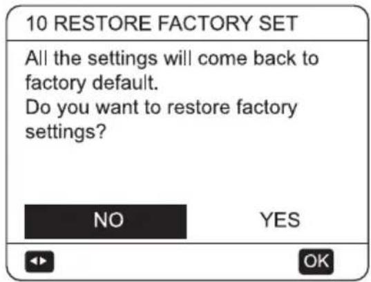
Press ◀▶ to scroll the cursor to YES and press √.
10 Start-up and configuration
The parameters related to this chapter are shown in the table below.
| Order number | Code State Default | Minimum Maximum | Setting interval | Unit | |||
| 1.1 Ta | Temperature difference between target LWT and real LWT for startup heat pump | 2 1 5 | 1 °C | ||||
| 1.2 Mp | Select priority mode 0 0 2 1 / | ||||||
| 1.3 T4L | Minimum ambient temp. of compressor operation for heating and hot water | -25 -40 | -21 1 °C | ||||
| 1.4 | PUMP_TYPE | Internal DC pump type | DC | DC | AC | 1 | / |
| 1.5 | SB-PWMout | Standby DC pump output | 35 | 10 | 100 | 1 | % |
| 1.6 | RUN-PWMout | Minimum DC pump operation output | 40 | 30 | 100 | 1 | % |
| 1.7 | IP | Address code | 0 | 0 | 15 | 1 | / |
| 1.8 TH4 | Enabel or disable chassis heater, 1=Enable, 0=Disable | 1 0 1 | 1 / | ||||
| 1.9 | a | Return difference in leaving water controller | 3 | 1 | 10 | 1 | °C |
| 1.10 | WPS | Enable or disable water pressure detect, 1=Enable, 0=Disable | 1 0 1 | 1 / | |||
| 1.11 | TE1 | Enable or disable TE1, NON=Disable, YES=Enable | NON | NON | YES | / | / |
| 1.12 | TE2 | Enable or disable TE2, NON=Disable, YES=Enable | NON | NON | YES | / | / |
| 1.13 | TZ2 | Enable or disable TZ2, NON=Disable, YES=Enable | NON | NON | YES | / | / |
| 1.14 | SMART GRID | Enable or disable SG, NON=Disable, YES=Enable | NON | NON | YES | / | / |
| 1.15 | dTE | Temperature difference between TE1 and target temp. | 15 | 0 | 50 | 1 °C | |
| 1.16 | t_SV3_ON | SV3 on time | 5 | 0 | 120 | 1 | MIN |
| 1.17 | t_SV3_OFF | SV3 off time | 2 | 0 | 120 | 1 | MIN |
| 1.18 | dT_SV3_ON | Temperature difference for SV3 ON | 5 | 0 | 10 | 1 | °C |
| 1.19 | dT_SV3_OFF | Temperature difference for SV3 OFF | 0 | -10 | 0 | 1 | °C |
| 1.20 | dTro | dTro means the control error of room temperature Tro to ON/OFF heat pump when enable room temperature Tro | 1 | 0.5 | 3 | 0.5 | °C |
| 1.21 | Tro-adj | Accuracy correction of room temperature sensor Tro | 0 | -10 | 10 | 1 °C | |
| 2.1 Tb | Temperature difference between target hot water and real tank water for startup heat pump | 5 2 | 15 | 1 °C |
10 Start-up and configuration
| Order number | Code State Default | Minimum Maximum | Setting interval | Unit | |||
| 2.2 Tx | Target disinfect temperature 65 55 75 1 °C | ||||||
| 2.3 Td | Disinfect running time 30 20 120 1 MIN | ||||||
| 2.4 | Teh | Ambient temperature of tank heater startup | 4 | -10 | 40 | 1 | °C |
| 2.5 P_d_DHW | Enable or disable tank pump control, NON=Disable, YES=Enable | NON | NON YES / | / | |||
| 2.6 P_d_DIS | Enable or disable tank pump in disinfect mode, NON=Disable, YES=Enable | YES | NON YES / | / | |||
| 2.7 P_d_TIME KEEP | Enable or disable tank pump operation timing, NON=Disable, YES=Enable | YES | NON YES / | / | |||
| 2.8 | t_P_d_on | Tank pump ON time | 15 | 5 | 120 | 1 | MIN |
| 2.9 | t_P_d_off | Tank pump OFF time | 120 | 5 | 180 | 1 | MIN |
| 2.10 | P_d_AUTO | Enable or disable tank pump normal ON, NON=Disable, YES=Enable | YES | NON YES / | / | ||
| 2.11 | TANK HEATER | Enable or disable tank heater, NON=Disable, YES=Enable | YES | NON YES / | / | ||
| 3.1 | HEAT TEMP. AUTO ADJUST | Enable or disable auto adjust in heating, 0=Disable, 1=Enable | 0 | 0 | 1 | 1 | / |
| 3.2 | Hi_A | High temperature compensation value | 5 | 0 | 20 | 1 | °C |
| 3.3 | Lo_A | Low temperature compensation value | 0 | -20 | 0 | 1 | °C |
| 3.4 | A | Maximum temperature compensation value | 5 | 0 | 10 | 1 | °C |
| 3.5 | HIGH TEMP HEAT OFF | Enable or disable high temperature shutdown, 0=Disable, 1=Enable | 0 | 0 | 1 | 1 | / |
| 3.6 T4h | Maximum shutdown T4 temperature | 24 10 30 1 °C | |||||
| 3.7 | H-PUMP | DC pump standby speed for heating | 3 | 0 | 3 | 1 | / |
| 3.8 HD | Enable or disable IPH or AHS, 0=Enable IPH, 1=Enable AHS | 1 | 0 | 1 | 1 | / | |
| 3.9 T4g | Ambient temperature of Enabling IPH or AHS | -20 | -20 | 20 1 °C | |||
| 3.10 | ZONE A HEAT-TYPE | Zone A heating terminal device type, 0=FCU, 1=RAD, 2=FLH | RAD | FCU | FLH | 1 | / |
| 3.11 | ZONE B HEAT-TYPE | Zone B heating terminal device type, 0=FCU, 1=RAD, 2=FLH | FLH | FCU | FLH | 1 | / |
| 3.12 | t_T4_FRESH_H | Refresh time of climate curve for heating | 30 | 30 | 360 | 10 | MIN |
| 3.13 | T4_ha1 | Auto climate curve ambient temp. 1 for heating | -5 | -25 | 35 1 °C | ||
| 3.14 | T4_ha2 | Auto climate curve ambient temp. 2 for heating | 7 | -25 | 35 1 °C | ||
10 Start-up and configuration
| Order number | Code State Default | Minimum Maximum | Setting interval | Unit | |||
| 3.15 SPTch_set1 | Auto climate curve target temp. 1 for heating | 35 25 | 60 1 °C | ||||
| 3.16 SPTch_set2 | Auto climate curve target temp. 2 for heating | 28 25 | 60 1 °C | ||||
| 4.1 C-Pump DC pump standby speed for cooling 3 0 3 1 / | |||||||
| 4.2 | ZONE A COOL TYPE | Zone A cooling terminal device type, 0=FCU, 1=RAD, 2=FLH | FCU FCU | FLH | 1 | / | |
| 4.3 | ZONE B COOL TYPE | Zone B cooling terminal device type, 0=FCU, 1=RAD, 2=FLH | FCU FCU | FLH | 1 | / | |
| 4.4 | t_T4_FRESH_C | Refresh time of climate curve for cooling | 30 | 30 | 360 | 10 | MIN |
| 4.5 T4_ca1 | Auto climate curve ambient temp. 1 for cooling | 25 | -5 | 46 1 °C | |||
| 4.6 T4_ca2 | Auto climate curve ambient temp. 2 for cooling | 35 | -5 | 46 1 °C | |||
| 4.7 | SPTcc_set1 | Auto climate curve target temp. 1 for cooling | 16 | 5 | 25 | 1 | °C |
| 4.8 | SPTcc_set2 | Auto climate curve target temp. 2 for cooling | 10 | 5 | 25 | 1 | °C |
| 5.1 | AUTO HEAT MAX T4 | Maximum ambient temp. of auto-heating mode | 17 10 | 17 1 °C | |||
| 5.2 | AUTO COOL MIN T4 | Minimum ambient temp. of auto-cooling mode | 25 20 | 29 1 °C | |||
| 6.1 ZONE TYPE | Two zones, ONE= single zone, TWO=duan zone | ONE | ONE | TWO | 1 | / | |
| 6.2 | SINGLE ZONE OPERATION SET | Single zone target temperature type 0 0 3 1 | / | ||||
| 6.3 | DUAL ZONE OPERATION SET | Dual zone target temperature type (2 and 6 for reserved) | 0 0 7 1 | / | |||
| 7.1 | ROOM THERMOSTAT | Room thermostat type, 0=NON=without room thermostat, 1=MODE SET, 2=ONE ZONE, 3=TWO ZONES | 0 0 3 1 | / | |||
| 7.2 | SINGLE ZONE RT OPERATION | Target temperature type on ROOM THERMOSTAT = MODE SET or ONE ZONE | 0 0 1 1 | / | |||
| 7.3 | DUAL ZONE RT OPERATION | Target temperature type on ROOM THERMOSTAT = TWO ZONES | 0 0 3 1 | / | |||
| 8.1 dTso | Temperature difference for startup solar pump | 10 | 2 | 20 1 °C | |||
| 8.2 | tso | Solar pump running time | 30 | 0 | 90 | 1 | MIN |
10 Start-up and configuration
| Order number | Code State Default | Minimum Maximum | Setting interval | Unit | |||
| 8.3 Solar_Type | Solar type, 0=NON, 1=Solar temp. sensor, 2=SL1SL2 | 0 0 2 | 1 / | ||||
| 8.4 AHS_Type | OF AHSDisable, 1=AHS with only heating, 2=AHS both heating and DHW | 0 0 2 | 1 / | ||||
| 9.1 PR | Enable or disable auto restart, 1=Enable, 0=Disable | 1 0 1 | 1 / | ||||
| 10.1 | YES to restore factory parameter setting, NO to exit restoring factory parameter setting | ||||||
The function description in the table below.
| Previous No. | parameter value function | ||
| 1.2 Mp | 0 hot water priority | ||
| 1 space heating/cooling priority | |||
| 2 Preemtpy | |||
| 1.3 | T4L | if ambient temperature less than T4L, do not turn on heat pump, but can turn on backup heater or AHS | |
| 1.4 | PUMP_TYPE | AC means internal water pump is alternating current; DC means internal water pump is PWM; | |
| 1.5 | SB-PWMout | means PWM pump running speed when heat pump is standby mode in which the compressor shuts down because of getting a target temperature | |
| 1.6 | RUN-PWMout | PWM pump must not operate below this speed when PWM pump is in speed adjustment | |
| 1.7 | IP | heat pump address code in group controller | |
| 1.11 | TE1 | to activate temperature sensor mounted on top of buffer tank in cascade mode, but the function is for reserved. | |
| 1.12 | TE2 | to activate temperature sensor mounted on bottom of buffer tank in cascade mode, for reserved | |
| 1.13 | TZ2 | to activate Zone 2 inlet temperature sensor function to get a low zone 2 target water temperature | |
| 1.15 | dTE | to activate Zone 2 inlet temperature sensor function to get a low zone 2 target water temperature | |
| 2.4 | Teh | if ambient temperature is higher than Teh, heat pump can't turn on hot water tank heater automatically unless manully turn on tank heater. | |
10 Start-up and configuration
| Previous No. | parameter value function | ||
| 2.10 P_d_AUTO | NON | water tank pump always runs and doesn't stop unless manully turn off tank pump | |
| YES and P_d_TIME KEEP is NON | water tank pump runs for the time (set by t_p_d_on) and then off | ||
| YES and P_d_TIME KEEP is YES | water tank pump runs by the cycle: on for the time (set by t_p_d_on) and then off for the time (set by t_p_d_off) | ||
| 3.1 | HEAT TEMP. AUTO ADJUST | to enable or disable adjusting the target water temperature by ambient temperature in heating mode | |
| 3.2 Hi_A | When T4 > Hi_A, the target temperature is judged according to SPTh-K, K= (T4-Hi_A)/2, and K does not exceed A (T4: ambient temp.) | ||
| 3.3 Lo_A | When T4 < Lo_A, the target temperature is judged according to SPTh+K, K= (Lo_A-T4)/2, and K does not exceed A (SPTh is setting water temperature) | ||
| 3.4 A | When Lo A≤T4≤Hi A, the target temperature is judged by SPTh | ||
| 3.5 | HIGH TEMP HEATOFF | enable or disable the function: don't turn on heat pump if ambient temperature is higher than T4h in heating mode | |
| 3.6 T4h | |||
| 3.7 H-PUMP | 0-State 1;1-State 2;2-State 3;3-State 4 | When the unit switches off in cooling or heating mode, the running state of DC pump can be set by the wire controller:State 1: the cycle is to be on 1 minute at the minimum output (30%) first, and then off 3 minutes.State 2: the cycle is to be on 1 minute at the minimum output (30%) first, and then off 10 minutes.State 3: the cycle is to be on 2 minutes at the minimum output (30%) first, and then off 15 minutes.State 4 (default state): to keep running at the minimum output (30%). | |
| 3.12 t_T4_FRESH_H | the controller refresh the ambient temperature by the time interval (set by t_T4_FRESH_H) when use weather temperature curve function in heating mode | ||
| 4.1 C-Pump to refer to the 3.9 H-PUMP | |||
| 4.4 t_T4_FRESH_C | the controller refresh the ambient temperature by the time interval (set by t_T4_FRESH_H) when use weather temperature curve function in cooling mode | ||
10 Start-up and configuration
| Previous No. | parameter value function | ||
| 6.2 | SINGLE ZONE OPERATION SET | 0=set water temp. (manually adjustment)1=set watertemp. (weather curve temp.)2=for reserved3=set room temp. (real weather curve temp.) | use it to set target temperature type when 6.1 ZONE TYPE = ONE (only one zone) |
| 6.3 | DUAL ZONE OPERATION SET | 1)=0: Zone 1 and Zone 2 are both water temp. (manually adjustment)2)=1: Zone 1 is water temp. (manually adjustment); Zone 2 is water temp. (weather curve temp.)3)=2: for reserved4)=3: Zone 1 is water temp. (manually adjustment); Zone 2 is room temp. (real weather curve temp.)5)=4: Zone 1 is water temp. (real weather curve temp.); Zone 2 is water temp. (manually adjustment)6)=5: Zone 1 and Zone 2 are both weather curve temp.7)=6: for reserved8)=7: Zone 1 is weather curve temp.; Zone 2 is room temp. (real weather curve temp.). | use it to set target temperature type when 6.1 ZONE TYPE=TWO (two zones) |
11 Test run and final checks
The installer is obliged to verify correct operation of unit after installation.
11.1 Final checks
Before switching on the unit, read following recommendations:
- When the complete installation and all necessary settings have been carried out, close all front panels of the unit and refit the unit cover.
- The service panel of the switch box may only be opened by a licensed electrician for maintenance purposes.

Note:
That during the first running period of the unit, required power input may be higher than stated on the nameplate of the unit. This phenomenon originates from the compressor that needs elapse of a 50 hours run in period before reaching smooth operation and stable power consumption.
In order to ensure optimal availability of the unit, a number of checks and inspections on the unit and the field wiring have to be carried out at regular intervals.
This maintenance needs to be carried out by your local technician.

Warning:
ELECTRIC SHOCK
- Before carrying out any maintenance or repairing activity, must switch off the power supply on the supply panel.
- Do not touch any live part for 10 minutes after the power supply is turned off.
- The crank heater of compressor may operate even in standby.
- Please note that some sections of the electric component box are hot.
- Forbid touch any conductive parts.
- Forbid rinse the unit. It may cause electric shock or fire.
Forbid leave the unit unattended when service panel is removed.
The following checks must be performed at least once a year by qualified person.
• Water pressure
Check the water pressure, if it is below 1 bar, fill water to the system.
- Water filter
Clean the water filter.
• Water pressure relief valve
Check for correct operation of the pressure relief valve by turning the black knob on the valve counter-clockWise:
- If you do not hear a clacking sound, contact your local dealer.
- In case the water keeps running out of the unit, close both the water inlet and outlet shut-off valves first and then contact your local dealer.
• Pressure relief valve hose
Check that the pressure relief valve hose is positioned appropriately to drain the water.
• Backup heater vessel insulation cover
Check that the backup heater insulation cover is fastened tightly around the backup heater vessel.
- Domestic hot water tank pressure relief valve (field supply) Applies only to installations with a domestic hot water tank. Check for correct operation of the pressure relief valve on the domestic hot water tank.
• Domestic hot water tank booster heater
Applies only to installations with a domestic hot water tank. It is advisable to remove lime buildup on the booster heater to extend its life span, especially in regions with hard water. To do so, drain the domestic hot water tank, remove the booster heater from the domestic hot water tank and immerse in a bucket (or similar) with lime-removing product for 24 hours.
- Unit switch box
- Carry out a thorough visual inspection of the switch box and look for obvious defects such as loose connections or defective wiring.
12 Maintenance and service
- Check for correct operation of contactors with an ohm meter. All contacts of these contactors must be in open position.
- Use of glycol (Refer to 9.4.4 "Water circuit anti-freeze protection") Document the glycol concentration and the pH-valve in the system at least once a year.
- -A PH-valve below 8.0 indicates that a significant portion of the inhibitor has been depleted and that more inhibitor needs to be added.
- -When the PH-valve is below 7.0 then oxidation of the glycol occurred, the system should be drained and flushed thoroughly before severe damage occurs.
Make sure that the disposal of the glycol solution is done in accordance with relevant local laws and regulations.
13 Trouble shooting
This section provides useful information for diagnosing and correcting certain troubles which may occur in the unit.
This troubleshooting and related corrective actions may only be carried out by your local technician.
13.1 General guidelines
Before starting the troubleshooting procedure, carry out a thorough visual inspection of the unit and look for obvious defects such as loose connections or defective wiring.

Warning:
When carrying out an inspection on the switch box of the unit, always make sure that the main switch of the unit is switched off.
When a safety device was activated, stop the unit and find out why the safety device was activated before resetting it. Under no circumstances can safety devices be bridged or changed to a valve other than the factory setting. If the cause of the problem cannot be found, call your local dealer.
If the pressure relief valve is not working correctly and is to be replaced, always reconnect the flexible hose attached to the pressure relief valve to avoid water dripping out of the unit!

Note:
For problems related to the optional solar kit for domestic water heating, refer to the troubleshooting in the Installation and owner's manual for that kit.
13.2 General symptoms
Symptom 1: The unit is turned on but the unit is not heating or cooling as expected
| Possible causes | Corrective action |
| The water flow is too low. | Check that all shut off valves of the water circuit are in the right position.Check if the water filter is plugged.Make sure there is no air in the water system.Check the water pressure.The water pressure must be >1 bar (water is cold).Make sure that the expansion vessel is not broken.Check that the resistance in the water circuit is not too high for the pump. |
| The water volume in the installation is too low. | Make sure that the water volume in the installation is above the minimum required valve (refer to "9.4.2 Water volume and sizing expansion vessels"). |
13 Trouble shooting
Symptom 2: Pump is making noise (cavitation)
| Possible causes | Corrective action |
| There is air in the system. | Purge air. |
| Water pressure at pump inlet is too low. | Check the water pressure.The water pressure must be >1 bar (water is cold).Check that the expansion vessel is not broken.Check that the setting of the pre- pressure of the expansion vessel is correct (refer to “9.4.2” Water volume and sizing expansion vessels”). |
Symptom 4: The water pressure relief valve leaks
| Possible causes | Corrective action |
| Dirt is blocking the water pressure relief valve outlet. | Check for correct operation of the pressure relief valve by turning the red knob on the valve counter clockWise:If you do not hear a clacking sound, contact your local dealer.In case the water keeps running out of the unit, close both the water inlet and outlet shut-off valves first and then contact your local dealer. |
Symptom 3: The water pressure relief valve opens
| Possible causes | Corrective action |
| The expansion vessel is broken. | Replace the expansion vessel. |
| The filling water pressure in the installation is higher than 0.3MPa. | Make sure that the filling water pressure in the installation is about 0.10~0.20 MPa (refer to "9.4.2 Water volume and sizing expansion vessels"). |
13 Trouble shooting
13.3 Parameter view
This menu is for installer or service engineer reviewing the operation parameters.
At home page, go to "☐> "PARAMETER VIEW".
Press "OK". There are twelve pages for the operating parameter as following. Use "▶", "◀", "▼", "▲" to scroll.
Press "▶" and "◀" to check slave units' operation parameter in cascade system. The address code in the upper right corner
| PARAMETER VIEW | 1/12 |
| 1 COMP. FREQUENCY | 55Hz |
| 2 EEV-1 OPEN | 480STEP |
| 3 AMBIENT TEMP. T4 | 30°C |
| 4 OUT WATER TEMP. TB | 30°C |
| 5 DISCHARGE TEMP. TP | 60°C |
| PARAMETER VIEW | 2/12 |
| 6 SUCTION TEMP. TH | 60°C |
| 7 COIL TEMP. T3 | 50°C |
| 8 LIQUID TEMP. T5 | 48°C |
| 9 PWM PUMP | OFF |
| 10 4-WAY VALVE | OFF |
| PARAMETER VIEW | 3/12 |
| 11 AC FAN | OFF |
| 12 SV1 STATUS | OFF |
| 13 SV2 STATUS | OFF |
| 14 IPH HEATER | OFF |
| 15 TANK HEATER | OFF |
| PARAMETER VIEW | 4/12 |
| 16 AC CURRENT | 0.0A |
| 17 INPUT VOLTAGE | 225V |
| 18 OIL RETURN | OFF |
| 19 HP2 | OFF |
| 20 CHASSIS HEATER | OFF |
| PARAMETER VIEW | 5/12 |
| 21 BUS VOLTAGE | 0VDC |
| 22 COMP.CURRENT | 0.0A |
| 23 PFC TEMP. | 0°C |
| 24 IPM TEMP. | 0°C |
| 25 DC FAN SPEED 1 | 770RPM |
| PARAMETER VIEW | 6/12 |
| 26 DC FAN SPEED 2 | 0RPM |
| 27 ECO. IN TEMP. | 0°C |
| 28 ECO. OUT TEMP. | 0°C |
| 29 TANK TEMP. | 50°C |
| 30 IN WATER TEMP.TA | 30°C |
| PARAMETER VIEW | 7/12 |
| 31 EEV-2 OPEN | OSTEP |
| 32 I-PUMP OUTPUT | 100% |
| 33 LOW SAT. TEMP. | 2°C |
| 34 CRANKCASE HEATER | OFF |
| 35 PLATE HEATER | OFF |
| PARAMETER VIEW | 8/12 |
| 36 IN WATER PRE. | 0.0bar |
| 37 OUT WATER PRE. | 2.0bar |
| 38 WATER FLOW | 0.0(m^3/h) |
| 39 WATER FLOW PWM | 100% |
| 40 UNIT MODEL | 4KW |
| PARAMETER VIEW | 9/12 |
| 41 SV3 | OFF |
| 42 FINAL TEMP. TC | 0°C |
| 43 SOLAR TEMP. Tso | 90°C |
| 44 BUFFER TEMP. TE1 | 20°C |
| 45 BUFFER TEMP. TE2 | 20°C |
| PARAMETER VIEW | 10/12 |
| 46 MIX IN TEMP. TZ2 | 20°C |
| 47 C-A CURVE TEMP. | 8°C |
| 48 H-A CURVE TEMP. | 32°C |
| 49 C-B CURVE TEMP. | 10°C |
| 50 H-B CURVE TEMP. | 35°C |
| PARAMETER VIEW | 11/12 |
| 51 AHS | OFF |
| 52 P_d | OFF |
| 53 P_o | OFF |
| 54 B ZONE P_c | OFF |
| 55 P_s | OFF |
| PARAMETER VIEW | 12/12 |
| 56 SG | OFF |
| 57 ROOM TEMP. Tro | 31°C |
| 58 SUC. PRESSURE | 0kPa |
| 59 GAS LEAKAGE RATE | 0% |

Note:
The flow rates parameters are calculated according to the pump running parameters, the deviation is different at different flow rates, the maximum of deviation is 15%. The flow parameters are calculated according to the electrical parameters of the pump operation.
For cascade application, after you select "PARAMETER VIEW" at home page, the screen will appear the page of selecting the module to be viewed:
Use four arrow keys to select the module and then press "OK" to go into "PARAMETER VIEW" menu. "MA." means master module, "SL." means slave module. Black arrow on the left of the module means the modules are online: one black arrow means the modules are online but currently not running, two black arrows means the modules are online and currently running. It's the online module that can be viewed the parameter.
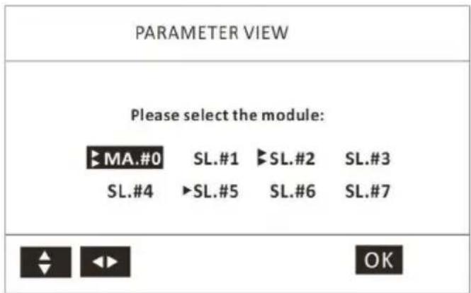
13.4 Error codes
When a safety device is activated, an error code (which does't include external failure) will be displayed on the user interface.
A list of all errors and corrective actions can be found in the table below.
Reset the safety by turning the unit OFF and back ON.
In case this procedure for resetting the safety is not successful, contact your local dealer.
Trouble shooting
Fault number
Fault name Failure analysis Diagnosis method Solution
| P01 | Water flow protection | 1. Lack of water in water system.2. Water flow switch is fault.3. Water system is blocked. | 1. Check whether the valve of water replenishing is off.2. Check whether the water flows witch is damage.3. Check whether the Y shape filter is blocked. | 1. Open the valve.2. Change the water flows witch.3. Clean or change the filternet. |
| P02 | High pressure protection | 1. Water flow is over low.2. High pressure switch is fault.3. Refrigerant system is blocked.4. EXV is locked. | 1. Check whether there is water shortage or insufficient pump flow;2. Check whether the high pressure switch is damage.3. Check whether the refrigerant system is blocked.4. Check whether there is EXV reset sound when the unit is standby, and power on or off. | 1. Refill water or Add an additional water pump.2. Change high pressure switch.3. Change the filter of refrigerant system.4. Change the EXV. |
| P03 | Low pressure protection | 1. Lack of refrigerant.2. Refrigerant system is blocked3. The unit is not running in regulations operating condition. | 1. Check whether the refrigerant system is leakage.2. Check whether the filter in refrigerant system is blocked.3. Check whether the outdoor ambient and the inlet water temperature is normal. | 1. Repair the leakage point.2. Change the filter of refrigerant system.3. If the ambient temperature and water temperature is too high or low, the unit will stop. |
| P04 | Condenser temperature over-heat protection | 1. Airflow of outdoor fan is insufficient.2. Condenser is too dirty.3. The temperature sensor (T3) is fault. | 1. Check whether there is any obstacle which is preventing the airflow.2. Check whether the condenser is too dirty.3. Check whether the condenser pipe temperature sensor (T3) is normal. | 1. Clean the vents2. Clean the condenser.3. Replace the temperature sensor. |
| P05 | Discharge temperature protection | 1. Lack of refrigerant.2. Discharge temperature sensor is fault. | 1. Check whether the refrigerant system is leakage.2. Check whether the discharge temperature sensor is normal. | 1. Repair the leakage point.2. Replace the temperature sensor |
| Fault number | Fault name Failure analysis Diagnosis method Solution | |||
| P06 | Anti-freezing protection of leaving water | 1. Water flow is too low.2. Heat-exchanger is blocked.3. Y shape filter in water system is blocked.4. Load is too low. | 1. Check whether there is some air in water circuit system.2. Check whether the heat-exchanger is blocked.3. Check whether the Y shape filter is blocked.4. Check whether the water circuit system is reasonable. | 1. If there is a problem with the drain valve, replace it with a new one;2. Blow the plate heat exchanger with water or high-pressure gas in the opposite direction for cleaning;3. Clean the filter;4. The water circulation system must have a shunt. |
| P07 | Anti-freezing protection of condenser pipe | 1. Lack of refrigerant.2. Water circuit system is blocked.3. Refrigerant system is blocked. | 1. Check for leaks in the system;2. Check whether Y shape filter is blocked.3. Check whether filter in refrigerant system is blocked. | 1. Repair the leakage point.2. Clean the filter.3. Replace the filter |
| P08 | Middle pressure protection | Middle pressure switch off | Check whether the middle pressure switch is open circuit, when turn off the unit. | Replace the middle pressure switch. |
| P10 | Low pressure sensorprotection | 1. Lack of refrigerant;2. The refrigeration system is blocked;3. Exceeding the scope of system work. | 1. Check whether the system is leaking;2. Check if the filter net is blocked;3. Check whether the ambient temperature or water temperature exceeds the limit. | 1. Repair the leak and refill the refrigerant;2. Replace the filter;3. Exceed the system working limit, can't run |
| P11 DC | Fan 1 failure | 1. The fan is faulty or stuck;2. The main control board is faulty | 1. Check whether the fan is stuck, or replace with a new fan;2. Replace the main control board | 1. Check if the fan is stuck, or replace with a new fan;2. Replace the main control board |
| P13 4-way valve fault | 1. Entering/leaving water temperature sensors are reversely inserted.2. 4-way valve is fault.3. PCB is fault. | 1. Check whether the entering and leaving temperature sensors are reversely inserted.2. Check whether action of 4-way valve is normal.3. Check whether the sample temperature of motherboard is accurate | 1. Correct the wrong place;2. Try to switch repeatedly to see if it works, if not, replace it;3. If it is wrong, replace it; | |
| Fault number | Fault name Failure analysis Diagnosis method Solution | |||
| P21 | DC pump is abnormal | The water pump is faulty or stuck;The system lacks water and is blocked;Main control board failure | Check whether the water pump is blocked, or replace with a new water pump;Check whether the system is short of water, whether it is blocked, and whether the valve is closed;Replace the main control board | Check if the water pump is blocked, or replace with a new water pump;Refill water or clean or replace the filter net and open the valve;Replace the main control board |
| P25 | Outlet pressure sensor failure | The sensor connection line is open or short-circuited;Sensor failure;The main control board is faulty; | Use a multimeter to check whether the sensor and connection are abnormal;Replace the faulty sensor with a normal sensor to confirm whether it is normal;Replace the main control board and confirm whether it is normal | Repair the connecting wire and plug or replace the sensor;Replace the mother-board; |
| E01 | Communication error of controller | The communication cable is disconnected;The wire controller is faulty;The main control board is faulty; | Check whether the communication cable is open or the plug is in poor contact;Confirm whether the wire controller is normal on a normal machine;Use a normal wire controller to confirm whether it is normal on the faulty machine; | Replace the communication cable or repair;Replace the line controller;Replace the main control board; |
| E02 | TP exhaust temperature sensor failure | The sensor connection line is open or short-circuited;Sensor failure;The main control board is faulty; | Use a multimeter to check whether the sensor and connection are abnormal;Replace the faulty sensor with a normal sensor to confirm whether it is normal;Replace the main control board and confirm whether it is normal; | Repair the connecting wire and plug or replace the sensor;Replace the mother-board; |
Trouble shooting
Fault number
Fault name Failure analysis Diagnosis method Solution
| E03 | T3 coil temperature sensor failure | 1. The sensor connection line is open or short-circuited;2. Sensor failure;3. Main control board failure | 1. Use a multimeter to check whether the sensor and connection are abnormal;2. Replace the faulty sensor with a normal sensor to confirm whether it is normal;3. Replace the main control board and confirm whether it is normal; | 1. Repair the connecting wire and plug or replace the sensor;2. Replace the mother-board; |
| E04 | T4 Ambient temperature sensor failure | 1. The sensor connection line is open or short-circuited;2. Sensor failure;3. Main control board failure | 1. Use a multimeter to check whether the sensor and connection are abnormal;2. Replace the faulty sensor with a normal sensor to confirm whether it is normal;3. Replace the main control board and confirm whether it is normal; | 1. Repair the connecting wire and plug or replace the sensor;2. Replace the mother-board;2. Replace the mother-board; |
| E05 | T5 liquid pipe temperature sensor failure | 1. The sensor connection line is open or short-circuited;2. Sensor failure;3. Main control board failure | 1. Use a multimeter to check whether the sensor and connection are abnormal;2. Replace the faulty sensor with a normal sensor to confirm whether it is normal;3. Replace the main control board and confirm whether it is normal; | 1. Repair the connecting wire and plug or replace the sensor;2. Replace the mother-board;1. Repair the connecting wire and plug or replace the sensor;2. Replace the mother-board; |
| E06 | TH return air temperature sensor failure | 1. The sensor connection line is open or short-circuited;2. Sensor failure;3. Main control board failure | 1. Use a multimeter to check whether the sensor and connection are abnormal;2. Replace the faulty sensor with a normal sensor to confirm whether it is normal;3. Replace the main control board and confirm whether it is normal; | 1. Repair the connecting wire and plug or replace the sensor;2. Replace the mother-board;3. Replace the main control board and confirm whether it is normal; |
| Fault number | Fault name Failure analysis Diagnosis method Solution | |||
| E07 | TW water tank temperature sensor failure | 1. The sensor connection line is open or short-circuited;2. Sensor failure;3. Main control board failure | 1. Use a multimeter to check whether the sensor and connection are abnormal;2. Replace the faulty sensor with a normal sensor to confirm whether it is normal;3. Replace the main control board and confirm whether it is normal; | 1. Repair the connecting wire and plug or replace the sensor;2. Replace the mother-board; |
| E08 | T6 Inlet water temperature sensor failure | 1. The sensor connection line is open or short-circuited;2. Sensor failure;3. Main control board failure | 1. Use a multimeter to check whether the sensor and connection are abnormal;2. Replace the faulty sensor with a normal sensor to confirm whether it is normal;3. Replace the main control board and confirm whether it is normal; | 1. Repair the connecting wire and plug or replace the sensor;2. Replace the mother-board;4. |
| E09 | T7 outlet water temperature sensor failure | 1. The sensor connection line is open or short-circuited;2. Sensor failure;3. Main control board failure | 1. Use a multimeter to check whether the sensor and connection are abnormal;2. Replace the faulty sensor with a normal sensor to confirm whether it is normal;3. Replace the main control board and confirm whether it is normal; | 1. Repair the connecting wire and plug or replace the sensor;2. Replace the mother-board:3. |
| E10 | Communication failure between main control board and drive board | 1. The communication cable is disconnected;2. The main control board is faulty;3. The drive module is faulty; | 1. Check whether the communication cable is open or the plug is in poor contact;2. Replace the main control board and confirm whether it is normal;3. Replace the drive board and confirm whether it is normal; | 1. Replace or repair the communication cable;2. Replace the main control board;3. Replace the drive module;4. |
| E14 | Low pressure sensor LPS failure | 1. The sensor connection line is open or short-circuited;2. Sensor failure;3. The main control board is faulty; | 1. Check whether the sensor and connection are abnormal;2. Replace the faulty sensor with a normal sensor to confirm whether it is normal;3. Replace the main control board and confirm whether it is normal; | 1. Repair the connecting wire and plug or replace the sensor;2. Replace the mother-board;3. |
13 Trouble shooting
| Fault number | Fault name Failure analysis Diagnosis method Solution | |||
| E15 | DC bus voltage is too low | Wiring error or IPM module failureCheck whether the wiring is wrong, reconnect the cable or replace the IPM module | ||
| E16 | DC bus voltage is too high | |||
| E17 | AC current protection (input current) | |||
| E18 | IPM module is abnormal | |||
| E19 PFC | abnormal | |||
13 Trouble shooting
| Fault number | Fault name Failure analysis Diagnosis method Solution | ||
| E20 | Compressor failed to start | Wiring error or IPM module failureCheck whether the wiring is wrong, reconnect the cable or replace the IPM module | |
| E21 | Compressor phase loss | ||
| E22 IPM | Module reset | ||
| E23 | Compressor over-current | ||
| E24 | PFC module temperature is too high | ||
| E25 | Current detection circuit failure | ||
| E26 Out of step | |||
| E27 | PFC module temperature sensor is abnormal | ||
| E28 | communication fail | ||
| E29 | IPM module temperature is too high | ||
| E30 | IPM module temperature sensor failure | ||
| E31 Reserved | |||
| E32 Reserved | |||
| E33 Reserved | |||
| E34 | AC input voltage is abnormal | ||
| E35 | Drive EEPROM error | ||
| E36 Power off reset | |||
| E37 Reserved | |||
| E38 Reserved | |||
13 Trouble shooting
| Fault number | Fault name Failure analysis Diagnosis method Solution | ||
| E49 | TC error the final water temperature sensor | Wiring error or the sensor fault:Check whether the wiring is wrong, reconnect the cable;Replace the sensor. | |
| E50 | Solar temperature sensor Tso error | ||
| E51 | The built-in temperature sensor Tro of the wire controller is faulty | ||
| E52 | Zone 2 temperature sensor TZ2 error | ||
| E53 | Up temperature sensor TE1 of buffer tank error | ||
| E54 | Down temperature sensor TE2 of buffer tank error | ||
| E56 | outlet water pressure sensor PS1error | ||
| E57 | GAS SENSOR OFFLINE | ||
| E58 | GAS SENSOR FAULT | ||
| E59 | MODULE OFFLINE | For CASCADE application, there are communication errors between master module and slave modules, please check whether the wiring is correct. | |
14 Technical specifications
14.1 General
| Model | 1 phase | ||||||
| GHPH-MM04 | GHPH-MM06 | GHPH-MM08 | GHPH-MM10 | GHPH-MM12 | GHPH-MM14 | GHPH-MM16 | |
| Nominal capacity Refer to the Technical Data | |||||||
| Weight | |||||||
| Net weight 78.5kg 80.5kg 82.5kg | 99kg | 108kg 1 | 24kg 124kg | ||||
| Gross weight 93.5kg 95.5kg 96kg | 114kg 1 | 23kg 142kg | 142kg | ||||
| Connections | |||||||
| water inlet/outlet 33mm | |||||||
| Water drain hose nipple | |||||||
| Expansion vessel | |||||||
| volume 5L | |||||||
| Maximum working pressure (MWP) | 3 bar | ||||||
| Pump | |||||||
| Type | water cooled | ||||||
| No. of speed | Variable speed | ||||||
| Pressure relief valve water circuit | 3 bar | ||||||
| Operation range - water side | |||||||
| heating | +12~+65°C | ||||||
| cooling | +5~+25°C | ||||||
| Operation range - air side | |||||||
| heating | -25 to 35°C | ||||||
| cooling | -5 to 43°C | ||||||
| domestic hot water by heat pump | -25 to 43°C | ||||||
14 Technical specifications
14.2 Electrical specifications
| Model | GHPH-MM04 GHPH-MM06 GHPH-MM08 GHPH-MM10 GHPH-MM12 GHPH-MM14 GHPH-MM16 | |
| Standard unit | Power Supply 220-240V~ | 50Hz |
| Nominal Running Current | See "9.7.4 Safety device requirement" | |
| Backup heater | Power Supply | See "9.7.4 Safety device requirement" |
| Nominal Running Current | ||
14.3 General (3-Phase)
| Model | 3 phase | ||
| 12kW 1 | 4kW 16kW | ||
| Nominal capacity Re | Refer to the Technical Data | ||
| Weight | |||
| Net weight 115kg 1 | 40kg 140kg | ||
| Gross weight 132kg | 159kg 159kg | ||
| Connections | |||
| water inlet/outlet 33mm | |||
| Water drain hose nipple | |||
| Expansion vessel | |||
| volume 5L | |||
| Maximum working pressure (MWP) | 3 bar | ||
| Pump | |||
| Type water cooled | |||
| No. of speed | Variable speed | ||
| Pressure relief valve water circuit | 3 bar | ||
| Operation range - water side | |||
| heating | +12~+65°C | ||
| cooling | +5~+25°C | ||
| Model | 3 phase | |
| 12kW 1 | 4kW 16kW | |
| Operation range - air side | ||
| heating | -25 to 35°C | |
| cooling | -5 to 43°C | |
| domestic hot water by heat pump | -25 to 43°C | |
14 Technical specifications
14.4 Electrical specifications (3-Phase)
| Model 3-phase 10/12/14/16kW | ||
| Standard unit | Power Supply 380-415V~ 50Hz | |
| Nominal Running Current See "9.7.4" Safety device requirement" | ||
| Backup heater | Power Supply | See "9.7.4" Safety device requirement" |
| Nominal Running Current | ||
14.5 Energy rating label and Specification sheet
Energy rating label
GHPH-MM08 GHPH-MM10 GHPH-MM12
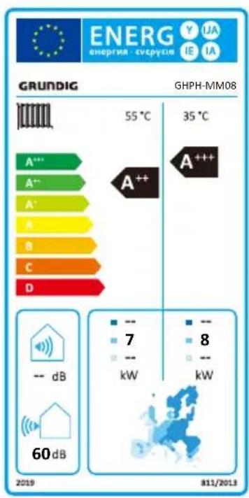
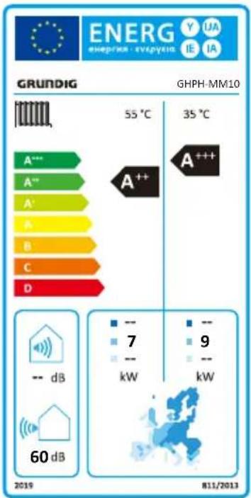
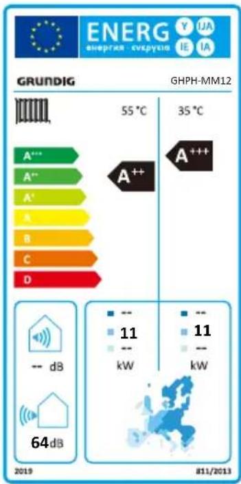
14 Technical specifications
GHPH-MM14 GHPH-MM16
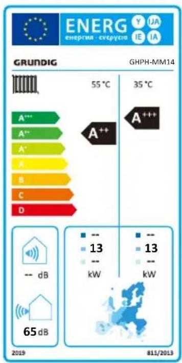
bar
GRUNDIG GHPH-MM14 | Category | Temperature (°C) | Energy Consumption (kW) | |---|---|---| | A*** | 55 | 13 | | A** | 35 | 13 | | A* | 35 | 13 | | A | 35 | 13 | | B | 35 | 13 | | C | 35 | 13 | | D | 35 | 13 | 2019 -- dB 65 dB 811/2013
14 Technical specifications
| Model name | GHPH-MM08 | GHPH-MM10 | GHPH-MM12 | GHPH-MM14 | GHPH-MM16 | |
| Refrigerant R32 R32 R32 R32 R32 | ||||||
| Total Refrigerant Amount | g 1300 1500 1750 2100 2100 | |||||
| GWP 675 675 675 675 675 | 675 | |||||
| Equivalent CO 2 | tonnes | 0.878 | 1.013 | 1.181 | 1.417 | 1.417 |
| PdesignC Capacity | 7.6 | 9.4 | 11.4 | 13.5 | 15.5 | |
| PdesignH Capacity (for low-temperature application) | 7.6 | 8.7 11.3 | 13.2 | 15 | ||
| PdesignH Capacity (for medium-temperature application) | 6.6 | 7.3 10.8 | 12.6 | 13 | ||
| Cooling Capacity (Outdoor air temperature 35°C DB,24°C WB; EWT 23°C, LWT 18°C) | kW | 8.2 | 10.0 | 11.9 | 14.1 | 15.7 |
| EER (Outdoor air temperature 35°C DB,24°C WB; EWT 23°C, LWT 18°C) | 4.65 | 4.14 | 4.36 | 4.56 | 3.90 | |
| Heating Capacity (Outdoor air temperature 7°C DB,6°CWB;EWT 30°C,LWT 35°C) | kW | 8.1 | 10.1 | 12.0 | 14.5 | 16.0 |
| COP (Outdoor air temperature 7°C DB,6°CWB; EWT 30°C, LWT 35°C) | 4.50 | 4.83 | 4.57 | 4.84 | 4.59 | |
14 Technical specifications
| Heating Capacity(Outdoor air temperature 7°CDB,6°C WB;EWT 47°C,LWT 55°C) | kW 7.7 | 9.6 | 12.3 | 14.4 | 16.2 | ||||
| COP(Outdoor air temperature 7°CDB,6°CWB;EWT 47°C,LWT 55°C) | 2.58 | 2.98 | 2.77 | 3.09 | 2.90 | ||||
| Rated Water Flow m | ^3/h | 1.38 | 1.72 | 2.06 | 2.41 | 2.75 | |||
| Rated Air Flow m | ^3/h | 3350 | 4050 | 4050 | 4650 | 4650 | |||
| Air Volume Of The Machine At Low Temperature Rated Condition | m^3/h | 3350 | 4050 | 4050 | 4650 | 4650 | |||
| Fan Input Power W 100 | 100 | 100 | 170 | 170 | |||||
| Rated Speed Of Fan rpm | 795 | 825 | 825 | 825 | |||||
| Sound power level | dBA | 60 | 60 | 64 | 65 | 68 | |||
| Voltage/Frequency/Phase | V/Hz/Ph | 220-240V~/50Hz/1 phase | 220-240V~/50Hz/1 phase | 220-240V~/50Hz/1 phase | 220-240V~/50Hz/1 phase | 220-240V~/50Hz/1 phase | |||
| Machine starting current | A | 1.87 | 2.42 | 2.65 | 3.24 | 3.24 | |||
| Cooling Rated Power Input | kW 3.7 | 4.3 | 5.5 | 5.9 | 6.8 | ||||
| Cooling Rated Current | A | 16.1 | 18.7 | 23.9 | 25.6 | 29.5 | |||
| Heating Rated Power Input(It relates to auxiliary electric heating power of 3kW) | kW 6.8 | 7.5 | 8.7 | 9.1 | 9.5 | ||||
| Heating Rated Current(It relates to auxiliary electric heating power current of 13.6A) | A | 29.5 | 32.6 | 37.8 | 39.6 | 41.3 |
14 Technical specifications
| Outlet water (Heating mode) | °C +25 ~ +65°C +25 ~ +65°C +25 ~ +65°C +25 ~ +65°C | |||||
| Outlet water (Cooling mode) | °C +7 ~ +25°C +7 ~ +25°C +7 ~ +25°C +7 ~ +25°C | |||||
| Domestic hot water °C | +25 ~ +60°C +25 ~ +60°C +25 ~ +60°C +25 ~ +60°C | |||||
| Ambient temperature °C | -25 ~ +43°C -25 ~ +43°C -25 ~ +43°C -25 ~ +43°C | |||||
| Max Water Pressure MPa 1.0 1.0 1.0 1.0 | ||||||
| Rated Water Pressure | MPa 0.3 0.3 0.3 0.3 | |||||
| Operation Pressure (Low Side) | MPa 2.6 2.6 2.6 2.6 | |||||
| Operation Pressure (High Side) | MPa 4.5 4.5 4.5 4.5 4.5 | |||||
| Maximum Allowable Pressure | MPa 4.5 4.5 4.5 4.5 4.5 | |||||
| Waterproof Level | IPX4 | IPX4 | IPX4 | IPX4 | IPX4 | |
| Electric Shock Proof Grade | I | I | I | I | I | |
| Water Side Connection Diameter | mm | 33 | 33 | 33 | 33 | 33 |
| Electric Heater Power Input | kW | 3 | 3 | 3 | 3 | 3 |
| Power Supply Cord Specification | mm^2 | 3G10 mm^2 | 3G10 mm^2 | 3G10 mm^2 | 3G10 mm^2 | 3G10 mm^2 |
| Dimension (L×W×H) | mm | 1125*370*703 | 1135*396*803 | 1135*396*803 | 1203*436*860 | 1203*436*860 |
| Net Weight | kg | 82.5 | 99 | 108 | 124 | 124 |
| Water system capacity | L | 7 | 7.2 7.4 7.7 | 7.7 | ||
| Compressor oil type | FW68S | FW68S | FW68S | FW68S | FW68S | |
15 Information servicing
1) Checks to the area
Prior to beginning work on systems containing flammable refrigerants, safety checks are necessary to ensure that the risk of ignition is minimised. For repair to the refrigerating system, the following precautions shall be complied with prior to conducting work on the system.
2) Work procedure
Works shall be undertaken under a controlled procedure so as to minimise the risk of a flammable gas or vapour being present while the work is being performed.
3) General work area
All maintenance staff and others working in the local area shall be instructed on the nature of work being carried out. work in confined sapces shall be avoided. The area around the work space shall be sectioned off. Ensure that the conditions within the area have been made safe by control of flammable material.
4) Checking for presence of refrigerant
The area shall be checked with an appropriate refrigerant detector prior to and during work, to ensure the technician is aware of potentially flammable atmospheres. Ensure that the leak detection equipment being used is suitable for use with flammable refrigerants, i.e. no sparking, adequately sealed or intrinsically safe.
5) Presence of fire extinguisher
If any hot work is to be conducted on the refrigeration equipment or any associated parts, appropriate fire extinguishing equipment shall be
available to hand. Have a dry power or CO_2 fire extinguisher adjacent to the charging area.
6) No ignition sources
No person carrying out work in relation to a refrigeration system which involves exposing any pipe work that contains or has contained flammable refrigerant shall use any sources of ignition in such a manner that it may lead to the risk of fire or explosion. All possible ignition sources, including cigarette smoking, should be kept sufficiently far away from the site of installation, repair- ing, removing and disposal, during which flammable refrigerant can possibly be released to the surrounding space. Prior to work taking place, the area around the equipment is to be surveyed to make sure that there are no flammable hazards or ignition risks. NO SMOKING signs shall be displayed.
7) Ventilated area
Ensure that the area is in the open or that it it adequately ventilated before breaking into the system or conducting any hot work. A degree of ventilation shall continue during the period that the work is carried out. The ventilation should safely disperse any released refrigerant and preferably expel it externally into the atmosphere.
8) Checks to the refrigeration equipment
Where electrical components are being changed, they shall be fit for the purpose and to the correct specification. At all times the manufacturer's maintenance and service guidelines shall be followed. If in doubt consult the manufacturer's technical department for assistance. The following checks shall be applied to installations using flammable refrigerants.
15 Information servicing
- The charge size is in accordance with the room size within which the refrigerant containing parts are installed.
- The ventilation machinery and outlets are operating adequately and are not obstructed.
- If an indirect refrigerating circuit is being used, the secondary circuits shall be checked for the presence of refrigerant; marking to the equipment continues to be visible and legible.
- Marking and signs that are illegible shall be corrected.
- Refrigeration pipe or components are installed in a position where they are unlikely to be exposed to any substance which may corrode refrigerant containing components, unless the components are constructed of materials which are inherently resistant to being corroded or are suitably protected against being so corroded.
9) Checks to electrical devices
Repair and maintenance to electrical components shall include initial safety checks and component inspection procedures. If a fault exists that could compromise safety, then no electrical supply shall be connected to the circuit until it is satisfactorily dealt with. If the fault cannot be corrected immediately but it is necessary to continue operation, and adequate temporary solution shall be used. This shall be reported to the owner of the equipment so all parties are advised.
Initial safety checks shall include:
- That capacitors are discharged: this shall be done in a safe manner to avoid possibility of sparking.
- That there no live electrical components and wiring are exposed while charging, recovering or purging the system.
• That there is continuity of earth bonding.
10) Repairs to sealed components
a) During repairs to sealed components, all electrical supplies shall be disconnected from the equipment being worked upon prior to any removal of sealed covers, etc. If it is absolutely necessary to have an electrical supply to equipment during servicing, then a permanently operating form of leak detection shall be located at the most critical point to warn of a potentially hazardous situation.
b) Particular attention shall be paid to the following to ensure that by working on electrical components, the casing is not altered in such a way that the level of protection is affected. This shall include damage to cables, excessive number of connections, terminals not made to original specification, damage to seals, incorrect fitting of glands, etc.
• Ensure that apparatus is mounted securely.
- Ensure that seals or sealing materials have not degraded such that they no longer serve the purpose of preventing the ingress of flammable atmospheres. Replacement parts shall be in accordance with the manufacturer's specifications.

Notes:
The use of silicon sealant may inhibit the effectiveness of some types of leak detection equipment. Instrinsically safe components do not have to be isolated prior to working on them.
11) Repair to intrinsically safe components
Do not apply any permanent inductive or capacitance loads to the circuit without ensuring that this will not exceed the permissible voltage and current permitted for the equipment in use. Intrinsically safe components are the only types that can be worked on while live in the presence of a flammable atmosphere. The test apparatus shall be at the correct rating. Replace components only with parts specified by the manufacturer. Other parts may result in the ignition of refrigerant in the atmosphere from a leak.
12) Cabling
Check that cabling will not be subject to wear, corrosion, excessive pressure, vibration, sharp edges or any other adverse environmental effects. The check shall also take into account the effects of aging or continual vibration from sources such as compressors or fans.
13) Detection of flammable refrigerants
Under no circumstances shall potential sources of ignition be used in the searching for or detection of refrigerant leaks. A halide torch (or any other detector using a naked flame) shall not be used.
14) Leak detection methods
The following leak detection methods are deemed acceptable for systems containing flammable refrigerants. Electronic leak detectors shall be used to detect flammable refrigerants, but the sensitivity may not be adequate, or may need re-calibration. (- Detection equipment shall be calibrated in a refrigerant-free area.) Ensure that the detector is not a potential source of ignition and is suitable for the refrigerant. Leak detection equipment shall be set at a percentage of the LFL of the refrigerant and shall be calibrated to the refrigerant employed and the appropriate percentage of gas (25% maximum) is confirmed. Leak detection fluids are suitable for use with most refrigerants but the use of detergents containing chlorine shall be avoided as the chlorine may react with the refrigerant and corrode the copper pipe-work. If a leak is suspected, all naked flames shall be removed or extinguished. If a leakage of refrigerat is found which requires brazing, all of the refrigerant shall be recovered from the system, or isolated (by means of shut off valves) in a part of the system remote from the leak. Oxygen free nitrogen (OFN) shall then be purged through the system both before and during the brazing process.
15) Removal and evacuation
When breaking into the refrigerant circuit to make repairs of for any other purpose conventional procedures shall be used, However, it is important that best practice is followed since flammability is a consideration. The following procedure shall be adhered to:
- Remove refrigerant;
• Purge the circuit with inert gas; - Evacuate;
15 Information servicing
• Purge again with inert gas;
- Open the circuit by cutting or brazing.
The refrigerant charge shall be recovered into the correct recovery cylinders. The system shall be flushed with OFN to render the unit safe. This process may need to be repeated several times.
Compressed air or oxygen shall not be used for this task.
Flushing shall be achieved by breaking the vacuum in the system with OFN and continuing to fill until the working pressure is achieved, then venting to atmosphere, and finally pulling down to a vacuum. This process shall be repeated until no refrigerant is within the system.
When the final OFN charge is used, the system shall be vented down to atmospheric pressure to enable work to take place. This operation is absolutely vital if brazing operations on the pipework are to take place.
Ensure that the outlet for the vacuum pump is not closed to any ignition sources and there is ventilation available.
16) Charging procedures
In addition to conventional charging procedures, the following requirements shall be followed:
- Ensure that contamination of different refrigerants does not occur when using charging equipment. Hoses or lines shall be as short as possible to minimize the amount of refrigerant contained in them.
• Cylinders shall be kept upright. - Ensure that the refrigeration system is earthed prior to charging the system with
refrigerant.
- Label the system when charging is complete (if not already).
- Extreme care shall be taken not to overfill the refrigeration system.
- Prior to recharging the system it shall be pressure tested with OFN. The system shall be leak tested on completion of charging but prior to commissioning. A follow up leak test shall be carried out prior to leaving the site.
17) Decommissioning
Before carrying out this procedure, it is essential that the technician is completely familiar with the equipment and all its detail. It is recommended good practice that all refrigerants are recovered safely. Prior to the task being carried out, an oil and refrigerator sample shall be taken.
In case analysis is required prior to re-use of reclaimed refrigerant. It is essential that electrical power is available before the task is commenced.
a) Become familiar with the equipment and its operation.
b) Isolate system electrically
c) Before attempting the procedure ensure that:
- Mechanical handling equipment is available, if required, for handling refrigerant cylinders.
- All personal protective equipment is available and being used correctly.
- The recovery process is supervised at all times by a competent person.
- Recovery equipment and cylinders conform to the appropriate standards.
d) Pump down refrigerant system, if possible.
e) If a vacuum is not possible, make a manifold so that refrigerant can be removed from
15 Information servicing
various parts of the system.
f) Make sure that cylinder is situated on the scales before recovery takes place.
g) Start the recovery machine and operate in accordance with manufacturer's instructions.
h) Do not overfill cylinders. (No more than 80% volume liquid charge).
i) Do not exceed the maximum working pressure of the cylinder, even temporarily.
j) When the cylinders have been filled correctly and the process completed, make sure that the cylinders and the equipment are removed from site promptly and all isolation valves on the equipment are closed off.
k) Recovered refrigerant shall not be charged into another refrigeration system unless it has been cleaned and checked.
18) Labelling
Equipment shall be labelled stating that it has been de-commissioned and emptied of refrigerant. The label shall be dated and signed. Ensure that there are labels on the equipment stating the equipment contains flammable refrigerant.
19) Recovery
When removing refrigerant from a system, either for service or decommissioning, it is recommended good practice that all refrigerants are removed safely.
When tranferring refrigerant into cylinders, ensure that only appropriate refrigerant recovery cylinders are employed. Ensure that the correct numbers of cylinders for holding the total system charge are available. All cylinders to be used are designated for the recovered refrigerant and
labelled for that refrigerant (i.e special cylinders for the recovery of refrigerant). Cylinders shall be complete with pressure relief valve and associated shut-off valves in good working order.
Empty recovery cylinders are evacuated and, if possible, cooled before recovery occurs.
The recovery equipment shall be in good working order with a set of instructions concerning the equipment that is at hand and shall be suitable for the recovery of flammable refrigerants. In addition, a set of calibrated weighing scales shall be available and in good working order.
Hoses shall be complete with leak-free disconnect couplings and in good condition. Before using the recovery machine, check that it is in satisfactory working order, has been properly maintained and that any associated electrical components are sealed to prevent ignition in the event of a refrigerant release. Consult manufacturer if in doubt.
The recovered refrigerant shall be returned to the refrigerant supplier in the correct recovery cylinder, and the relevant Waste Transfer Note arranged. Do not mix refrigerants in recovery units and especially not in cylinders.
If compressors or compressor oils are to be removed, ensure that they have been evacuated to an acceptable level to make certain that flammable refrigerant does not remain within the lubricant. The evacuation process shall be carried out prior to retruning the compressor to the suppliers. Only electric heating to the compressor body shall be employed to accelerate this process. When oil is drained from a system, it shall be carried out safely.
15 Information servicing

Notes:
Only VC (VCL) compressor oil can be added.
20) Transportation, marking and storage for units
Transport of equipment containing flammable refrigerants Compliance with the transport regulations.
Marking of equipment using signs Compliance with local regulations.
Disposal of equipment using flammable refrigerants Compliance with national regulations.
Storage of equipment/appliances.
The storage of equipment should be in accordance with the manufacturer's instructions.
Storage of packed (unsold) equipment.
Storage package protection should be constructed such that mechanical damage to the equipment inside the package will not cause a leak of the refrigerant charge.
The maximum number of pieces of equipment permitted to be stored together will be determined by local regulations.
ANNEX A: Refrigerant cycle
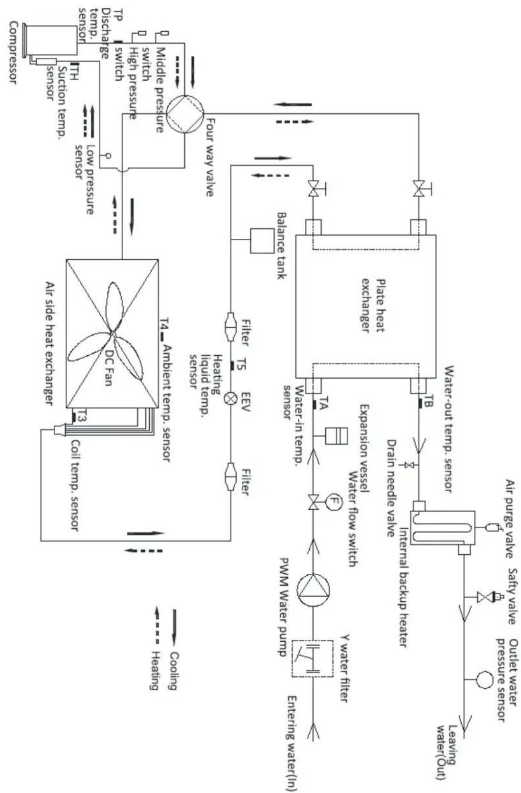
flowchart
graph TD
    A["Living water (Out)"] --> B["Leaving water (in)"]
    B --> C["Y water filter"]
    C --> D["PWM water pump"]
    D --> E["Expansion vessel"]
    E --> F["Water flow switch"]
    F --> G["Water-in temp. sensor"]
    G --> H["Plate heat exchanger"]
    H --> I["Drain needle valve"]
    I --> J["Internal backup heater"]
    J --> K["Water-out temp. sensor"]
    K --> L["Balance tank"]
    L --> M["Four way valve"]
    M --> N["Combpressor"]
    N --> O["TH"]
    O --> P["Suction temp. sensor"]
    P --> Q["Low pressure sensor"]
    Q --> R["Air side heat exchanger"]
    R --> S["DC Fan"]
    S --> T["T4 Ambient temp. sensor"]
    T --> U["Heat/liquid temp. sensor"]
    U --> V["Filter"]
    V --> W["Filter"]
    W --> X["EV"]
    X --> Y["Filter"]
    Y --> Z["Heating"]
    Z --> AA["Cooling"]
    AA --> AB["Heating"]
15 Information servicing
ANNEX K:
Electrical wiring diagram of the unit (GHPH-MM04, GHPH-MM06)
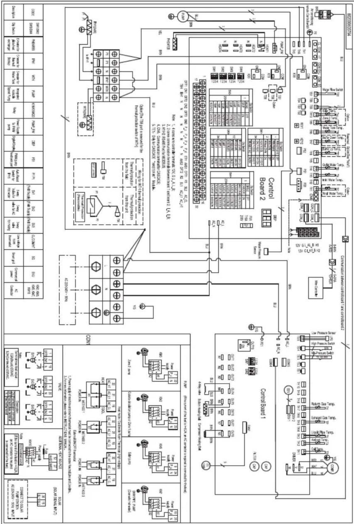
15 Information servicing
Electrical wiring diagram of the unit (GHPH-MM08, GHPH-MM10, GHPH-MM12)

15 Information servicing
ANNEX K:
Electrical wiring diagram of the unit (GHPH-MM14, GHPH-MM16)
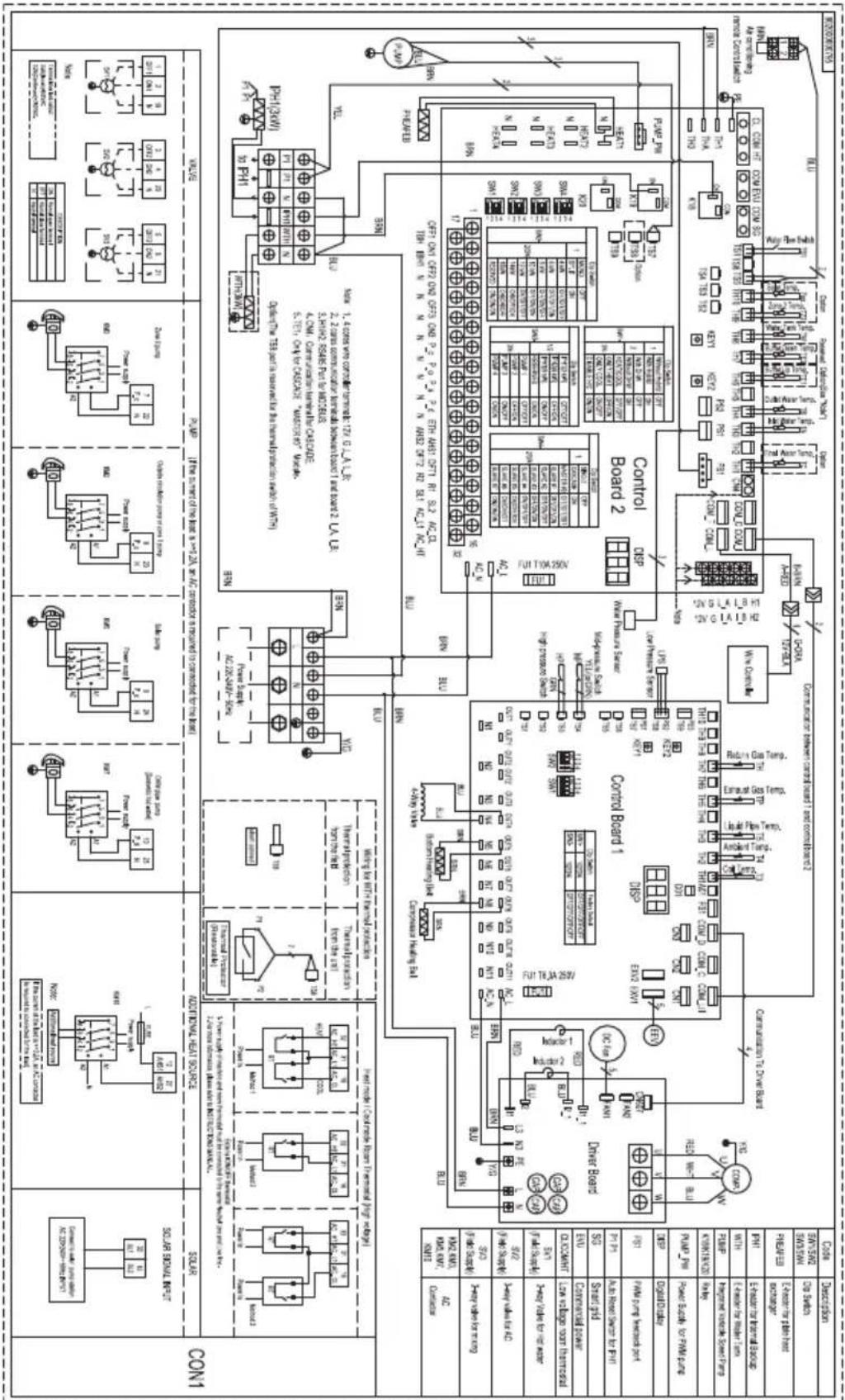
Electrical wiring diagram of the unit (3-phase 10\~16kW)
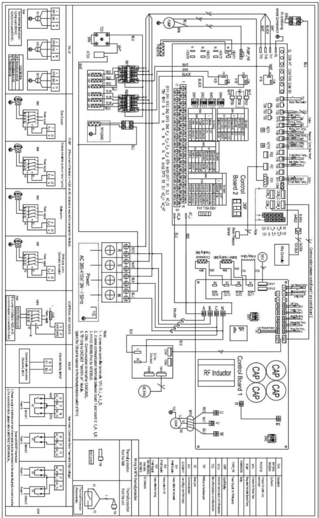
16 European disposal guidelines
This appliance contains refrigerant and other potentially hazardous materials. When disposing of this appliance, the law requires special collection and treatment, Do not dispose of this product as household waste or unsorted municipal waste.
When disposing of this appliance, you have the following options:
- Dispose of the appliance at designated municipal electronic waste collection facility.
- When buying a new appliance, the retailer will take back the old appliance free of charge.
- The manufacturer will take back the old appliance free of charge.
- Sell the appliance to certified scrap metal dealers.

Special notice: Disposing of this appliance in the forest or other natural surroundings endangers your health and is bad for the environment. Hazardous substances may leak into the ground water and enter the food chain.

natural_image
Symbol of a trash bin with crossed lines indicating no waste or discharge, and a solid black rectangle below (no text or labels)This symbol indicates that this product shall not be disposed with other household wastes at the end of its service life. Used device must be returned to official collection point for recycling of electrical and electronic devices. To find these collection systems please contact to your local authorities or retailer where the product was purchased. Each household performs important role in recovering and recycling of old appliance. Appropriate disposal of used appliance helps prevent potential negative consequences for the environment and human health.
17 F-Gas instruction
This product contains fluorinated greenhouse gases.
The fluorinated greenhouse gases are contained in hermetically sealed equipment.
Installs, services, maintains, repairs, checks for leaks or decommissions equipment and product recycling should be carried out by natural persons that hold relevant certificates.
If the system has a leakage detection system installed, leakage checks should be performed at least every 12 months, make sure system operate properly.
If product must be performed leakage checks, it should specify Inspection cycle, establish and save records of leakage checks.

For hermetically sealed equipment, portable air conditioner, window air conditioner and dehumidifier, if CO_2 equivalent of fluorinated greenhouse gases is less than 10 tonnes, it should not perform leakage checks.
natural_image
Pure electrical circuit lines without any symbols4/6/8 kW

natural_image
Pure mechanical component diagram with no text, numbers, or symbols10/12 kW

natural_image
Pure diagram of a rectangular frame with a patterned internal structure, no text or symbols present.14/16kW

line
| TB | T4 | | --- | --- | | 5 | 19 | | 11 | 10 | | 25 | -5 | | 50 | 43 |area
| TB | T4 | | --- | --- | | 5 | 35 | | 12 | 35 | | 25 | 35 | | 40 | -25 | | 45 | -20 | | 50 | -15 | | 55 | -10 | | 60 | -5 | | 65 | 0 |area
| TB | T4 | | --- | --- | | 5 | 43 | | 12 | 43 | | 25 | 43 | | 40 | -25 | | 45 | -20 | | 50 | -15 | | 55 | -10 | | 60 | -5 | | 65 | 0 |natural_image
Technical diagram showing a rectangular panel with vertical stripes and a side view labeled A and B (no text or symbols beyond labels)natural_image
Line drawing of a white industrial enclosure with a black panel, set against a brick wall (no text or symbols)| Unité A (mm) | |
| 4~16 kW ≥300 |
natural_image
Technical line drawing of a modular storage unit with vertical supports and a textured panel, set against a brick wall background (no text or symbols)| Unité B (mm) | |
| 4~6 kW ≥1000 | |
| 8~16 kW ≥1500 |
natural_image
Line drawing of a rectangular industrial machine with a black panel on the left and a digital display on the right (no text or symbols)natural_image
Simple line drawing of a house with a hanging box and a cross symbol (no text or labels)natural_image
Diagram of a window with vertical slats and a horizontal hatched base, no text or symbols present| Unité A (mm) B1 (mm) B2 (mm) | C (mm) | |||
| 4~12 kW ≥2500 ≥1000 | ≥300 ≥600 | |||
| 14~16 kW ≥3000 ≥1500 | ||||
natural_image
Front view of a blackboard with vertical white lines and a small ruler on the left side (no text or symbols visible)4/6/8 kW 10/12 kW 14/16 kW

natural_image
Pure electrical circuit lines without any symbols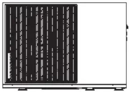
natural_image
Front view of a black electronic device with vertical white lines on the left side, mounted on a stand (no visible text or symbols)
Avertissement :
natural_image
Technical line drawing of an industrial machine with no visible text or symbolsnatural_image
Diagram of a room with a monitor, ladder, and air flow system (no text or symbols)
Remarque :
natural_image
Technical line drawing of a mechanical assembly with rollers and shafts (no text or symbols)
Remarques :
natural_image
Technical line drawing of a mechanical assembly with pipes and housing (no text or symbols)Remarques :
natural_image
Simple icon of two cylindrical objects inside a container with a checkmark (no text or symbols)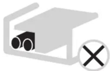
natural_image
Simple diagram of a device with two cylindrical components and a cross symbol (no text or labels)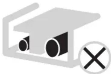
natural_image
Simple diagram of a roof structure with circular openings and a cross symbol (no text or labels)UNIT POWER SUPPLY (ALIMENTATION DE L'APPAREIL) monophasé
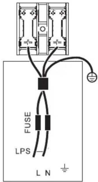
UNIT POWER SUPPLY (ALIMENTATION DE L'APPAREIL) monophasé
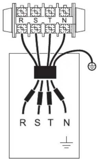
UNIT POWER SUPPLY (ALIMENTATION DE L'APPAREIL) triphasée
Remarques :
natural_image
Diagram of a yellow cable or pipe connecting a grid structure with a hook, no text or symbols present| 3 HEAT MODE | 4/4 |
| 3.16 SPTch_set2 | 28°C |
10.5.4 COOL MODE SETTING (RÉGLAGE DU MODE REFROIDISSEMENT)
13.4 Codes d'erreur
ANNEXE K :