DXGNR6500 - Generator DEWALT - Free user manual and instructions
Find the device manual for free DXGNR6500 DEWALT in PDF.

| Product type | Portable generator |
| Brand | DeWalt |
| Model | DXGNR6500 |
| Dimensions (L x W x H) | 692 x 696 x 724 mm |
| Weight | 75 kg |
| Fuel | Unleaded gasoline (minimum 87 octane) |
| Rated power (continuous) | 6.5 kW (6500 W) |
| Peak power | 8.125 kW (8125 W) / 10 kVA |
| Output voltage | 120/240 V AC, single-phase, 60 Hz |
| Outlets | 2x double GFCI 120 V / 20 A, 1x locking 120/240 V / 30 A |
| Fuel tank capacity | 28.4 L |
| Runtime at 50% load | 10 hours |
| Starting type | Manual (recoil start) and electric (12 V battery) |
| Engine | 389 cc, single-cylinder |
| Engine oil capacity | 1 L (SAE 30 recommended) |
| Spark plug | Gap 0.7-0.8 mm |
| Battery (electric start models) | 12 V DC, 10 Ah |
| CO protection | CO Protect system with automatic shutdown |
| Low oil protection | Automatic engine shutdown |
| Circuit breakers | Push-button for 120 V outlets, bipolar for 240 V outlet |
| Sound level | Muffler with spark arrestor |
| Included accessories | Wheels, handle, battery charger, tool kit |
| Recommended maintenance | Oil change every 100 h, air filter every 200 h |
Frequently Asked Questions - DXGNR6500 DEWALT
User questions about DXGNR6500 DEWALT
0 question about this device. Answer the ones you know or ask your own.
Ask a new question about this device
Download the instructions for your Generator in PDF format for free! Find your manual DXGNR6500 - DEWALT and take your electronic device back in hand. On this page are published all the documents necessary for the use of your device. DXGNR6500 by DEWALT.
USER MANUAL DXGNR6500 DEWALT
If you have questions or comments, contact us.
1-888-431-6871 · dewalt.com
INSTRUCTION MANUAL
DEWALT®
Generator DXGNR6500
DXGNR8000
WARNING
To reduce the risk of injury, read and follow these instructions before operating product.
! WARNING
CANCER AND REPRODUCTIVE HARM
www.P65Warnings.ca.gov.
(000393a)
Safety 2
Safety Guidelines and Definitions ......2
Safety Rules 2
Accessories 5
Service Information ....5
Repairs 5
Free Warning Label Replacement ....5
Assembly 7
Unpacking 7
Install Accessory Kits ....7
Battery Replacement/Connection ....8
Emissions Information 8
Operation 9
Know the Generator 9
Connection Plugs ....10
CO PROTECT 11
How to Use the Generator ....12
Know Generator Limits ....12
Wattage Reference Guide ....13
Before Starting Generator ....13
Starting Pull Start Engines 14
Starting Electric Start Engines 15
Manual Start 15
Generator Shut Down 15
Low Oil Level Shutdown System 16
Charging the Battery (electric start units only) 16
Maintenance 17
Maintenance Recommendations ....17
Maintenance Schedule 17
Product Specifications ....17
Preventive Maintenance ....17
Engine Maintenance ....18
Battery Replacement/Connection (if equipped) 19
Valve Clearance 19
Inspect Spark Arrester Screen ....20
Storage 20
Troubleshooting 21
Safety
Safety Guidelines and Definitions
! DANGER
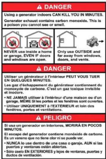
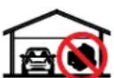
Using a generator indoors CAN KILL YOU IN MINUTES.
Generator exhaust contains carbon monoxide. This is a poison you cannot see or smell.

NEVER use inside a home or garage, EVEN IF doors and windows are open.
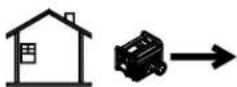
Only use OUTSIDE and far away from windows, doors, and vents.
000657
This instruction manual contains information important for you to know and understand so that your generator may properly, safely, and effectively be applied and operated. All operators, users and subsequent owners of this generator must read and understand all instructions before operating the generator. Save these instructions for future reference.
To help you recognize information important to protecting YOUR SAFETY and PREVENTING EQUIPMENT PROBLEMS, we use the symbols below.
DANGER
Indicates an imminently hazardous situation which, if not avoided, will
result in death or serious injury.
WARNING
Indicates a potentially hazardous situation which, if not avoided, could
result in death or serious injury.
CAUTION
Indicates a potentially hazardous situation which, if not avoided, may result
in minor or moderate injury.
NOTICE:
Indicates a practice not related to personal injury which, if not avoided, may
result in property damage.
Safety Rules
SPARK ARRESTING MUFFLER
Certain states and jurisdictions require that engine driven equipment be fitted with spark arresting mufflers. Depending on the generator model, spark-arresting mufflers may or may not be fitted. If spark-arresting mufflers are required for your location and the generator muffler is not spark arresting, contact your local dealer for instructions for a retrofit.
SPARK ARRESTOR
If the product will be used around flammable materials, such as agricultural crops, forests, brush, grass, or other similar items, then an approved spark arrester should be installed and is legally required in the State of California. The California statutes requiring a spark arrester are Sections 13005(b), 4442 and 4443. Spark Arresters are also required on some U.S. Forest Service land and may also be legally required under other statutes and ordinances. An approved spark arrester is provided and is also available from an Authorized DEWALT Service Center, or call 1-888-431-6871.
EXHAUST EMISSION CONTROL SYSTEM
The exhaust emission control system for this generator complies with the standards set forth by the California Air Resources Board (CARB) and the Environmental Protection Agency (EPA). The respective engine manufacturers administer warranties for the exhaust emission system. Refer to the engine documentation for warranty information.
WARNING
The engine exhaust from this product contains chemicals known to the State of California to cause cancer, birth defects, or other reproductive harm.
RISK OF ASPHYXIATION
DANGER
DO NOT OPERATE THIS GENERATOR WITHIN AN ENCLOSED AREA.
THE EXHAUST GASES OF THIS GENERATOR EMIT "DEADLY" CARBON MONOXIDE. EXPOSURE TO CARBON MONOXIDE CAN CAUSE CARBON MONOXIDE POISONING, HEADACHES, NAUSEA, SEVERE SICKNESS OR DEATH.
DANGER
IF YOU START TO FEEL SICK, DIZZY, OR WEAK AFTER THE GEN-
ERATOR HAS BEEN RUNNING, MOVE TO FRESH AIR IMMEDIATELY. SEE A DOCTOR, AS YOU COULD HAVE CARBON MONOXIDE POISONING.
DANGER
NEVER RUN A GENERATOR INDOORS OR IN A PARTLY
ENCLOSED AREA SUCH AS A GARAGE.
DANGER
ONLY USE OUTDOORS AND FAR AWAY FROM WINDOWS, DOORS,
VENTS, CRAWL SPACES AND IN AN AREA WHERE ADEQUATE VENTILATION IS AVAILABLE AND WILL NOT ACCUMULATE DEADLY EXHAUST GAS.
DANGER
USING A FAN OR OPENING A DOOR WILL NOT PROVIDE SUFFI-
CIENT VENTILATION.
DANGER
POINT MUFFLER EXHAUST AWAY FROM PEOPLE AND OCCUPIED
BUILDINGS.
RISK OF ELECTROCUTION OR SHOCK
DANGER
THIS GENERATOR SET PRO- DUCES ELECTRICAL CURRENT.
THEREFORE, SAFETY GUIDELINES MUST BE FOLLOWED. IMPROPER USE OF THIS GENERATOR CAN RESULT IN ELECTROCUTION, INJURY OR DEATH. DO NOT OPERATE, SERVICE OR REPAIR THIS GENERATOR UNLESS FULLY QUALIFIED TO DO SO.
DANGER
THIS GENERATOR SET IS DESIGNED TO BE OPERATED IN
DRY CONDITIONS AND FOR OUTDOOR AREAS ONLY. NEVER OPERATE THIS GENERATOR INDOORS. NEVER OPERATE THIS GENERATOR IN RAIN, SNOW, SLEET OR GENERALLY WET CONDITIONS. DAMAGE TO THE GENERATOR, BODILY INJURY, OR DEATH COULD RESULT FROM ELECTROCUTION.
DANGER
IF THIS GENERATOR IS CONNECTED TO A BUILDING, HOME,
BUSINESS, OR ANY OTHER ELECTRICAL CIRCUIT NORMALLY FED BY UTILITY POWER, STEPS MUST BE TAKEN TO ENSURE THE GENERATOR OUTPUT AND THE UTILITY POWER ARE POSITIVELY ISOLATED. THIS IS TYPICALLY ACCOMPLISHED THROUGH THE USE OF A PROPERLY INSTALLED TRANSFER SWITCH. FAILURE TO ISOLATE THE UTILITY AND GENERATOR ELECTRICAL SYSTEMS WILL RESULT IN GENERATOR DAMAGE AND COULD RESULT IN INJURY OR DEATH TO UTILITY WORKERS DUE TO THE BACKFEED OF ELECTRICITY.
DANGER
TO AVOID BACKFEEDING INTO UTILITY SYSTEMS, ISOLATION OF
THE RESIDENCE ELECTRICAL SYSTEM IS REQUIRED. BEFORE CONNECTION OF A GENERATOR TO THE RESIDENCE ELECTRICAL SYSTEM TURN OFF THE MAIN SWITCH. BEFORE MAKING PERMANENT CONNECTIONS A DOUBLE THROW TRANSFER SWITCH MUST BE INSTALLED. TO AVOID ELECTROCUTION OR PROPERTY DAMAGE, ONLY A TRAINED ELECTRICIAN SHOULD CONNECT GENERATOR TO RESIDENCE ELECTRICAL SYSTEM. CALIFORNIA LAW REQUIRES ISOLATION OF THE RESIDENCE ELECTRICAL SYSTEM BEFORE CONNECTING A GENERATOR TO RESIDENCE ELECTRICAL SYSTEMS. TEMPORARY CONNECTION NOT RECOMMENDED DUE TO BACKFEEDING.
ALWAYS FOLLOW LOCAL CODES AND REGULATIONS THAT APPLY TO THE INSTALLATION OF ANY ITEM THAT CONCERNS THIS PRODUCT.
- NFPA 70 - National Electrical Code.
- NFPA 37 - Standard for Installation and Use of Stationary Combustible Engines.
- Agricultural Wiring handbook of Farm Standby Electric Power.
DANGER
DO NOT MODIFY OR MISAPPLY YOUR GENERATOR SET. OPERA-
TION OF THE GENERATOR OTHER THAN INTENDED COULD RESULT IN GENERATOR SET DAMAGE, BODILY INJURY OR EVEN DEATH FROM ELECTROCUTION.
DANGER
NEVER TOUCH A RECEPTACLE OR BARE WIRE. ELECTROCUTION OR
SHOCK COULD RESULT.
RISK OF FIRE OR EXPLOSION
WARNING
ALWAYS INSURE THAT AT LEAST 6 FEET OF CLEARANCE ON ALL
SIDES OF THE GENERATOR ARE MAINTAINED DURING OPERATION. FAILURE TO MAINTAIN PROPER CLEARANCE COULD DAMAGE YOUR GENERATOR AND POTENTIALLY LEAD TO FIRES.
WARNING
GASOLINE IS HIGHLY FLAMMABLE AND ITS VAPORS ARE EXPLOSIVE.
FAILURE TO PROPERLY HANDLE GASOLINE CAN RESULT IN EXPLOSION OR FIRE. DO NOT PERMIT SMOKING WITHIN 50FT OF THIS GENERATOR SET.
WARNING
NEVER REFILL A HOT GENERATOR WITH FUEL. NEVER REFILL
THE GENERATOR WHILE IT IS RUNNING. SPILLAGE ONTO THE ENGINE OR GENERATOR COULD RESULT IN AN EXPLOSION OR FIRE. ALWAYS ALLOW THE GENERATOR SET TO COOL BEFORE REFILLING.
WARNING
DO NOT STORE THIS GENERATOR SET IN ANY LOCATION WHERE
GASOLINE FUMES COULD POTENTIALLY COME INTO CONTACT WITH SPARKS, A PILOT LIGHT OR AN OPEN FLAME. IMPROPER STORAGE OF THIS GENERATOR COULD RESULT IN AN EXPLOSION OR FIRE.
WARNING
INSPECT THE SPARK ARRESTOR PERIODICALLY. SPARK ARRES-
TORS ARE REQUIRED IN SOME AREAS AND MINIMIZE THE RISK OF FIRE FROM SPARKS EMITTED FROM THE EXHAUST.
WARNING
DO NOT OPERATE THIS GENERATOR IF THE AMBIENT TEMPERA-
TURE EXCEEDS 104°F/40°C.
WARNING
DO NOT EXCEED THE RATED CAPACITY OF THE GENERATOR.
THE TOTAL ELECTRICAL LOADS AT EACH OUTLET MUST BE ADDED TO DETERMINE THE TOTAL ELECTRICAL LOAD. THE TOTAL LOAD MUST NOT EXCEED THE RATED CAPACITY OF THE GENERATOR. IF THE DRIVEN APPARATUS DOES NOT LIST WATTAGE, BUT ONLY AMPERAGE, WATTAGE MAY BE DETERMINED BY MULTIPLYING AMPERAGE TIMES VOLTAGE (WATTS = AMPS X VOLTS).
GENERAL SAFETY
Always follow National and Local electrical codes pertaining to generators. All local and national codes supersede rules or information provided in this manual.
WARNING
REFER TO LOCAL AND NATIONAL ELECTRICAL CODES TO DETER-MINE GROUNDING REQUIREMENTS AS THIS CAN VARY PER APPLICATION. THE GENERATOR IS GROUNDED INTERNALLY NEUTRAL TO FRAME. WHERE APPLICATIONS REQUIRE EXTERNAL GROUNDING, A CONNECTION MUST BE MADE FROM THE GENERATOR TO A SOLID EARTH GROUND. A CONTINUOUS LENGTH OF SPLICE-FREE COPPER CABLE, NO SMALLER THAN 6 AWG, SHALL BE USED FOR THE CONDUCTOR.
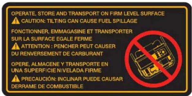
- When moving or transporting this generator, take proper precautions to avoid fuel spillage. Further, always use common sense when lifting this generator. An adequate number of people and proper lifting methods must be used.
- Do not cover the generator while it is running or immediately after shutdown. Always allow time to cool down before covering.
- Do not operate this generator unless it is in good mechanical and electrical condition.
• Always keep hands, body parts, hair and clothing well away from the rotating parts of the generator. - Do not start this generator with connected devices turned "ON". Always make sure that connected devices are disconnected from the generator or turned "OFF" before starting the generator.
- Generators operating on job or construction sites may be required to have GFCI (Ground Fault Circuit Interrupters) receptacles.
- Use only grounded extension cords in good condition and make sure that the wire size within the extension cords is of sufficient size to safely carry the surge output of the outlet the cord is plugged into.
- Never handle extension cords or electrical circuits if standing in water or if standing in a damp area.
RISK OF BODILY INJURY
WARNING
KEEP HANDS, BODY PARTS, HAIR AND CLOTHING AWAY FROM THE"HOT" PARTS OF THE GENERATOR SET DURING AND AFTER OPERATION. THE EXHAUST SYSTEM, AND THE GENERATOR IN GENERAL, CAN REMAIN VERY HOT EVEN AFTER BEING SHUT DOWN.
WARNING
DO NOT TAMPER WITH THE ENGINE-GOVERNED SPEED. THEGENERATOR OPERATES AT A NOMINAL SPEED OF 3600 RPM. INCREASES IN SPEED OVER THE 3600 RPM NOMINAL WILL INCREASE THE CHANCE OF PERSONAL INJURY DUE TO ROTATIONAL STRESSES ON THE ROTATING MEMBERS. OPERATION OF THE GENERATOR AT SPEEDS BELOW THE NOMINAL 3600 RPM COULD CAUSE DAMAGE TO THE GENERATOR OR DRIVEN APPARATUS DUE TO LOW VOLTAGE OUTPUT.
CAUTION
EQUIPMENT DAMAGE. DO NOT POWER SENSITIVE ELECTRONIC DEVICES (COMPUTERS, TELEVISIONS, MICRO-WAVES...) WHEN IDLE CONTROL SWITCH IS ON (IF EQUIPPED). LOWER ENGINE RPM OPERATION RESULTS IN LOW VOLTAGE/FREQUENCY AND MAY DAMAGE ELECTRONIC DEVICES. (000591)
BATTERY SAFETY
WARNING
STORAGE BATTERIES PRODUCE AND RELEASE EXPLOSIVE HYDROGEN GAS WHEN CHARGING. THE SLIGHT-EST SPARK, FLAME OR BURNING ASH CAN IGNITE THESE GASES CAUSING A SERIOUS EXPLOSION THAT COULD RESULT IN BLINDNESS OR OTHER SERIOUS INJURIES. WEAR EYE PROTECTION, RUBBER APRON AND RUBBER GLOVES WHEN WORKING AROUND A BATTERY OR PERFORMING BATTERY SERVICE. BATTERY FLUID IS AN EXTREMELY CAUSTIC SULFURIC ACID, WHICH CAN CAUSE SEVERE BURNS. ALWAYS DISCONNECT THE NEGATIVE (-) BATTERY CABLE FROM THE BATTERY BEFORE PERFORMING BATTERY SERVICE OR BEFORE PERFORMING ANY ELECTRICAL SERVICE ON THE GENERATOR OR ENGINE.
ENVIRONMENTAL PROTECTION
CAUTION
INSPECT THE EXHAUST SYSTEM REGULARLY TO ENSURE IT ISFUNCTIONING PROPERLY. LEAKY EXHAUST SYSTEMS WILL INCREASE NOISE LEVELS.
CAUTION
DIRECT THE "LOUD" SIDES OF THE GENERATOR INTO OPEN SPACESAVOIDING REVERBERATION FROM WALLS OR BUILDINGS THUS AMPLIFYING THE SOUND.
NOTICE:
NEVER DRAIN OR DISPOSE OF ENGINE OIL INTO THE GROUND OR DOMESTIC WASTE WATER SYSTEMS.
RAISING OR SUSPENDING GENERATOR
WARNING
Always use cables, chains or straps rated at 2000 lbs. working load or more to raise or suspend generator.
WARNING
Never operate generator while suspended. This could cause property damage, serious injury or death.
WARNING
Make sure all fasteners in frame and lifting hook are tight.
NOTICE:
Make sure the generator is in a level position before raising or suspending to
prevent damage.
Accessories
Recommended accessories for use with your tool are available for purchase from your local dealer or authorized service center. If you need assistance in locating any accessory for your tool, please contact an Authorized DEWALT Service Center, call 1-888-431-6871 or visit our website www.dewalt.com.
• 006948 - Lifting Eye Kit
Service Information
Please have the following information as shown listed on the data label available for all service calls:
| Model No. | |
| Serial No. | |
| Date of Purchase | |
| Place of Purchase |
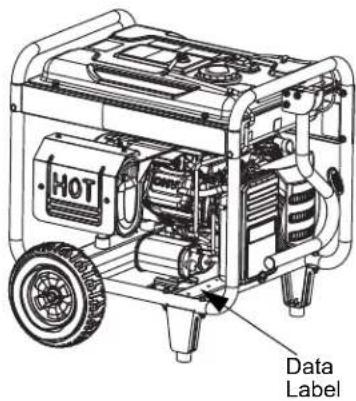
000756
Repairs
To assure product SAFETY and RELIABILITY, repairs, maintenance and adjustment should be performed by an Authorized DEWALT Service Center. Call 1-888-431-6871. Always use identical replacement parts.
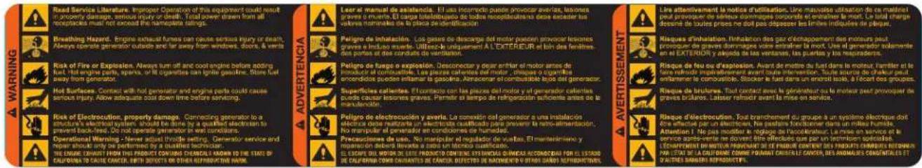
Free Warning Label Replacement
If your warning labels become illegible or are missing, call 1-888-431-6871 for a free replacement.

- Remove all packaging material.
- Remove separate accessory kit box.
- Remove generator from carton.
Accessories
Check contents against the list in Table -1. If any parts are missing or damaged, or if any problems occur during assembly, call the Generator Helpline at 1-888-431-6871.
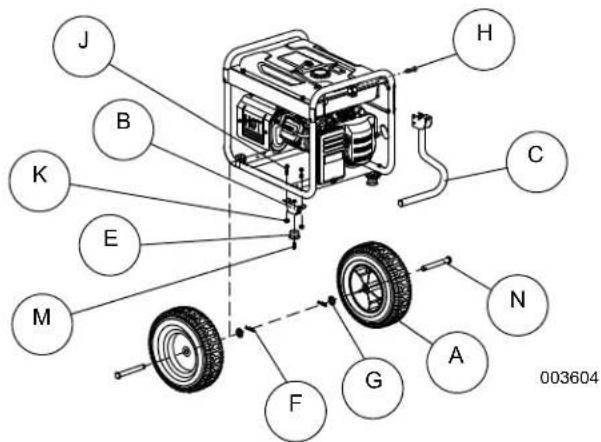
Table -1. Contents
| Item | 6500 8000 | |
| Qty. Qty. | ||
| Generator 1 1 | ||
| Owner's Manual 1 1 | ||
| Product Registration Card (English, Spanish, and French) | 3 | 3 |
| Service and Emissions Warranty | 1 1 | |
| Liter SAE 30 Oil | 1 1 | |
| Battery Charger (electric start models) | - | 1 |
| Wheel (A) | 2 2 | |
| Frame Foot (B) | 2 2 | |
| Handle Assembly (C) | 1 1 | |
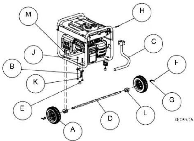
| Axle (D) | - | 1 |
| Hardware Bag | ||
| Rubber Foot (E) | 2 2 | |
| Cotter Pin (F) | 2 2 | |
| 1/2" Flat Washer (G) | 2 2 | |
| M8 Carriage Bolt (H) | 2 2 | |
| M8 Bolt (long) (J) | 4 4 | |
| M8 Hex Flange Nut (K) | 6 6 | |
| Axle Bracket (L) | - | 2 |
| M6 Bolt (M) | - | 4 |
| 1/2" Axle Pin (N) | 2 | - |
| M6 Hex Flange Nut (P) | 2 2 | |
Install Accessory Kits
The generator requires some minor assembly before use.
Tools Required
Obtain the following tools:
- Two 10mm, 12mm and 13mm box wrenches
- Two 8mm box wrenches (8000W models)
Install Wheel Kit (If Equipped)
The wheels are specially designed to enhance portability.
NOTICE:
The wheels are not intended for over-the-road use.
DXGNR6500
- Slide axle pin (N) through wheel, 1/2" flat washer (G), and wheel bracket on frame.
- Insert cotter pin (F) and bend tabs to lock in place.
DXGNR8000
- Slide M6 bolt (M) through holes in frame rail. Install into axle bracket (L).
- Slide axle (D) through axle bracket (L), wheel (A), and into 12 " flat washer (G). Insert hair pin (F) through axle (D).
Install Frame Foot and Rubber Bumpers
- Slide rubber foot (E) through frame foot (B). Install locking flange nuts (K).
- Slide M8 bolt (J) through holes in frame rail. Slide frame foot (B) onto M8 bolts. Install locking flange nuts (K).
Install Handle
- Slide M8 carriage bolt (H) through handle bracket and handle assembly (C) by first inserting the bolt through the square hole in the handle assembly (C).
- Install M8 flange nut (K).
Battery Replacement/Connection
NOTICE:
The battery shipped with the generator has been fully charged. A battery may
lose some charge when not in use for prolonged periods of time. If battery is unable to crank engine, plug in the 12V charger included in the accessory box (see Charging the Battery (electric start units only)
IMPORTANT: Running the generator does not charge battery.
WARNING
Accidental Start-up. Disconnect the negative battery cable, then the posi-
tive battery cable when working on unit. Failure to do so could result in death or serious injury.
- Disconnect negative (-) battery terminal FIRST (A).
- Disconnect positive (+) battery terminal SECOND (B).
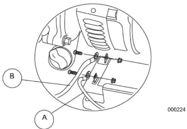
- Install new battery. Install hold down bracket and tighten.
- Connect positive (+) battery terminal (B) FIRST (B). Slide rubber boot over connection hardware.
- Connect negative (-) battery terminal (A) SECOND.
- Slide rubber boot over connection hardware.
Emissions Information
The Environmental Protection Agency and California Air Resource Board “for generators certified to CA standards” requires that this generator comply with exhaust and evaporative emission standards. Locate the emissions compliance decal on the engine to determine what standards the generator meets. This generator is certified to operate on gasoline. The emission control system includes the following components (if equipped):
• Air Induction System
- Intake Pipe / Manifold
- Air Cleaner
- Fuel System
- Carburetor
- Fuel Tank / Cap
- Fuel Lines
- Evaporative Vent Lines
- Carbon Canister
- Ignition System
- Spark Plug
- Ignition Module
- Exhaust System
- Exhaust Manifold
-M uffler - Pulsed Air Valve
- Catalyst
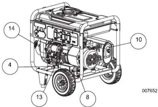
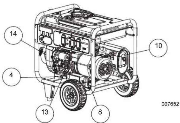
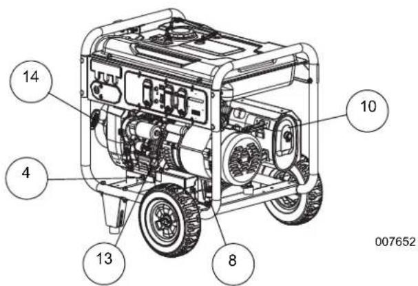
Know the Generator
Carefully read the Instruction Manual and Safety Rules before operating the generator. Save this manual for future reference.
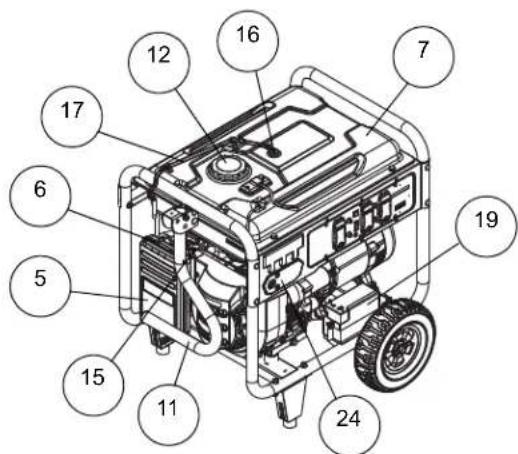
Become familiar with locations of all components.
- 120 Volt AC, 20 Amp GFCI Duplex Outlets – Supplies electrical power for the operation of 120 Volt AC, 20 Amp, single-phase, 60 Hz, electrical lighting, appliance, tool and motor loads. It also provides protection with an integral Ground Fault Circuit Interrupter, complete with a press to TEST and RESET button (NEMA 5-20R).
- 120/240 Volt AC, 30 Amp Locking Receptacle – Supplies electrical power for operation of 120 and/or 240 Volt AC, 30 Amp, single-phase, 60 Hz, electrical lighting, appliance, tool and motor loads (NEMA L14-30R).
-
Circuit Breakers (AC) - Models with 120V receptacles provide a push-to-reset circuit breaker to protect the generator against electrical overload. Models with 240V Twistlock receptacles provide 2-pole circuit breakers.
-
Oil Drain – Use to drain engine oil.
-
Air Filter – Filters intake air as it is drawn into the engine.
-
Choke Lever – Used when starting a cold engine.
-
Fuel Tank – See Product Specifications for tank capacity.
-
Grounding Lug – Ground the generator to an approved earth ground here. See Grounding Generator If Used as Portable for details.
-
Start/Run/Stop Switch - Used to start engine from the starter motor (electric start models only). Must be in Run position to start manually.
-
Muffler – Quiets the engine.
-
Handle - Pivot and retract for storage. Press the spring-loaded button to move handle.
-
Gas Cap – Fuel fill location.
-
Oil Fill – Add and check oil here.
-
Recoil Starter – Use to start engine manually.
-
Fuel Shut Off – Valve between fuel tank and carburetor.
-
Roll Over Valve – Passes fuel vapors to the engine airbox.
-
Recovery Hose – Install between the carbon canister and the roll over valve (if equipped).
-
Battery Charger Input - This receptacle allows the capability to recharge the 12 volt DC storage battery provided with the 12 Volt Adaptor Plug Charger which is included in the Accessory Box. Located behind the battery charger input is a 1.50 Amp in-line fuse which is inside the control panel to protect the battery (electric start models only).
-
Battery – Powers the electric starter (electric start models only).
-
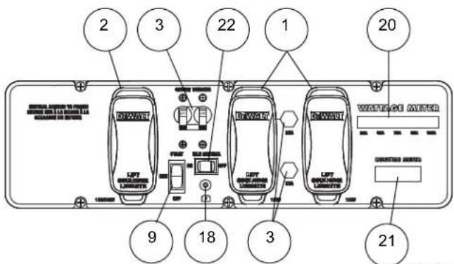
Wattage Meter – Indicates the amount of power being used from the generator (8000W models only).
-
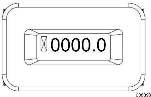
Runtime Meter – Displays the total unit run hours for a short duration before providing available run time given the load currently applied, and remaining fuel volume.
NOTICE:
Operate unit on level ground for runtime meter accuracy.
-
Idle Control Switch – Operates the engine at normal (high) rpm when there is an electrical load present and automatically reduces the engine to a lower rpm when a load is not present. The system can also be turned off to operate the engine at a higher rpm at all times.
-
Hour Meter – Tracks hours of operation for scheduled maintenance.
-
CO Protect – Carbon monoxide automatic shut down.
DXGNR 6500
003606
DXGNR 8000
007651
Hour Meter (if equipped)
The Hour Meter tracks hours of operation for scheduled maintenance.
- The CHG OIL display will illuminate every 100 hours. The message will flash one hour before and one hour after each 100 hour interval, providing a two hour window to perform service.
- The SVC display will illuminate every 100 hours. The message will flash one hour before and one hour after each 200 hour interval providing a two hour window to perform service.
When the hour meter is in flash alert mode, the maintenance message will alternate with elapsed time in hours and tenths. The hours will flash four times, then alternate with the maintenance message four times until the meter automatically resets.
• 100 hours - CHG OIL — Oil Change Interval (Every 100 hrs)
• 200 hours - SVC — Service Air Filter (Every 200 hrs)
NOTICE: The hour glass icon will flash when the engine is running. This signifies the
meter is recording hours of operation.
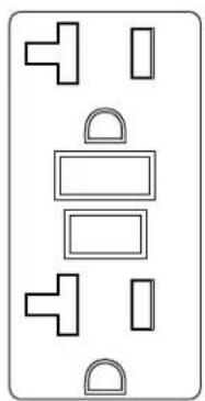
Connection Plugs
120 VAC, 20 Amp, GFCI Duplex Receptacle
This is a 120 Volt outlet protected against overload by a 20 Amp push-to-reset circuit breaker. Use each socket to power 120 Volt AC, single phase, 60 Hz electrical loads requiring up to a combined 2400 watts (2.4 kW) or 20 Amps of current. Use only high quality, well-insulated, 3-wire grounded cord sets rated for 125 Volts at 20 Amps (or greater).
natural_image
Pure electrical circuit lines without any symbols000203
120/240 VAC, 30 Amp Receptacle
Use a NEMA L14-30 plug with this receptacle (rotate to lock/unlock). Connect a suitable 4-wire grounded cord set to the plug and to the desired load. The cord set should be rated for 250 Volts AC at 30 Amps (or greater). Use this receptacle to operate 120 Volt AC, 60 Hz, single phase loads requiring up to 3600 watts (3.6 kW) of power at 30 Amps or 240 Volt AC, 60 Hz, single phase loads requiring up to 7200 watts (7.2 kW) of power at 30 Amps. The outlet is protected by a 30 Amp double-pole circuit breaker.

natural_image
Circular diagram with concentric rings and a central cross-like pattern (no text or symbols)000204
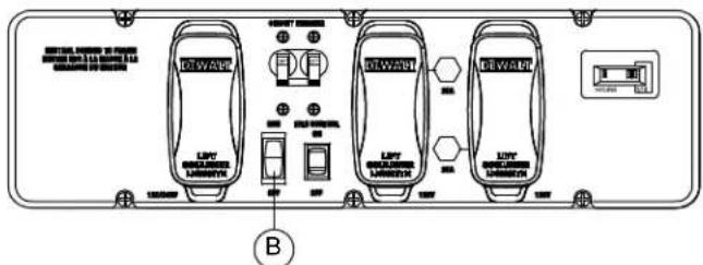
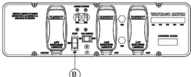
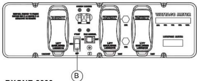
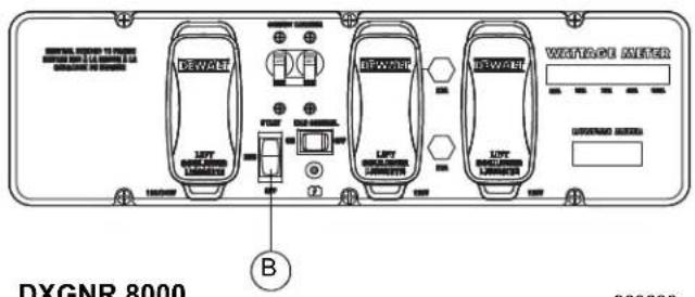
Idle Control Switch
When this switch is ON, the engine operates at normal (high) rpm when there is an electrical load present and automatically reduces the engine to a lower rpm when a load is not present. When this switch is OFF the engine operates at normal (high) rpm.
Ensure this switch is OFF when starting or stopping the engine, or for use with a transfer switch.
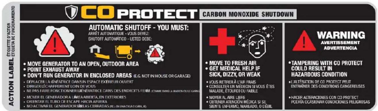
CO PROTECT
Carbon Monoxide (CO) Detection and Shut-off System (if equipped)
The CO PROTECT module monitors for the accumulation of poisonous CO gas found in engine exhaust when the generator is running. If CO PROTECT detects increasing levels of CO gas, it automatically shuts off the engine. CO PROTECT only monitors when the engine is running. Generators are intended to be used outdoors, far from occupied buildings and the exhaust pointed away from personnel and buildings. However, if misused and operated in a location that results in the accumulation of CO, like a house or even a garage with partially opened door, CO PROTECT shuts off the engine, notifies the user of what has happened and directs the user to read the instruction action label for steps to take. CO PROTECT is not a substitute for an indoor carbon monoxide alarm.
As the user approaches the generator to investigate a shut-off, a blinking RED light in the CO PROTECT badge on the side of the generator provides notification that the generator was shut off due to an accumulating CO hazard. The RED light will blink for at least five minutes after a CO shut-off. Move the generator to an open, outdoor
area and point the exhaust away from people and occupied buildings. Once relocated to a safe area, the generator can be restarted and the proper electrical connections made to supply electrical power. The RED light will stop blinking automatically upon engine re-start. Introduce fresh air and ventilate the location where the generator had shut down.
If a CO PROTECT system fault has occurred and no longer provides protection, the portable generator is shut off automatically and the YELLOW light will blink for at least five minutes in the CO PROTECT badge to notify the user of the fault. The CO PROTECT module can only be diagnosed and repaired by a trained technician at the dealer. The generator can be re-started, but may continue to shut-off.
CO PROTECT will detect the accumulation of Carbon Monoxide from other fuel burning sources such as engine powered tools or propane heaters used in the area of operation. For example, if another generator is used and the exhaust is pointed at a CO PROTECT equipped generator, CO PROTECT may initiate a shut-off due to rising CO levels. This is not an error. Hazardous Carbon Monoxide has been detected. The user must take action to move and re-direct these devices to better dissipate Carbon Monoxide far away from personnel and occupied buildings.

How to Use the Generator
If there are any problems operating the generator, call the generator helpline at 1-888-431-6871.
DANGER
Never operate in an enclosed area or indoors! NEVER use in the home, in a
vehicle, or in partly enclosed areas such as garages, EVEN IF doors and windows are open! ONLY use outdoors and far from open windows, doors, vents, and in an area that will not accumulate deadly exhaust.
DANGER
The engine exhaust fumes contain carbon monoxide, which cannot be
seen or smelled. The gas is poisonous, and if breathed in sufficient concentrations, can cause unconsciousness or even death.
DANGER
Adequate, unobstructed flow of cooling and ventilating air is critical to gen-
erator operation. Do not alter the installation or permit even partial blockage of ventilation provisions, as this can seriously affect safe operation of the generator. The generator MUST be operated outdoors.
DANGER
The exhaust system must be properly maintained. Do nothing that might
render the exhaust system unsafe or in noncompliance with any local codes and/or standards.
DANGER
Always use a battery operated carbon monoxide alarm indoors. Be sure it is
properly installed according to the manufacturers instructions.
! DANGER
Using a generator indoors CAN KILL YOU IN MINUTES.
Generator exhaust contains carbon monoxide. This is a poison you cannot see or smell.

NEVER use inside a home or garage, EVEN IF doors and windows are open.


Only use OUTSIDE and far away from windows, doors, and vents.
000657
Grounding Generator If Used as Portable
An equipment ground connects the generator frame components to ground terminals on the AC output receptacles. This allows the generator to be used as a portable without grounding the frame as specified in NEC 250.34. Neutral bonded to frame.
Special Requirements
There may be Federal or State Occupational Safety and Health Administration (OSHA) regulations, local codes, or ordinances that apply to the intended use of the generator.
Consult a qualified electrician, electrical inspector, or the local agency having jurisdiction:
- In some areas, generators are required to be registered with local utility companies.
- If the generator is used at a construction site, there may be additional regulations which must be observed.
Connecting to Building Electrical System
Use a manual transfer switch when connecting directly to a building electrical system. Installation and connections must be performed by a qualified electrician and in strict compliance with all national and local electrical codes and laws.
Always operate the generator with the idle control switch OFF.
natural_image
Technical line drawing of an electric motor with internal stator and rotor blades (no text or symbols)000227
Know Generator Limits
Overloading a generator in excess of its rated wattage capacity can result in damage to the generator and to connected electrical devices. Observe the following rules to avoid overloading:
- Add up the total wattage of all electrical devices to be connected at one time. The total should NOT be greater than the wattage capacity of the generator.
- The rated wattage of lights can be taken from light bulbs. The rated wattage of tools, appliances and motors can usually be found on a data label or decal affixed to the device.
- If the appliance, tool or motor does not give wattage, multiply volts times ampere rating to determine watts (volts x amps = watts).
-
Some electric motors, such as induction types, require about three times more watts of power for starting than for running. This power surge lasts only a few seconds. To allow for high starting wattage when selecting electrical devices to connect to the generator, proceed as follows:
-
Figure the watts needed to start the largest motor.
- Add to that figure the running watts of all other connected loads.
- See Subsection Wattage Reference Guide for help in determining how many items the generator can operate at one time.
NOTICE:
All figures are approximate. See data label on appliance for actual wattage
requirements.
Wattage Reference Guide Before Starting Generator
| Device | Running Watts |
| *Air Conditioner (12,000 Btu) | 1700 |
| *Air Conditioner (24,000 Btu) | 3800 |
| *Air Conditioner (40,000 Btu) | 6000 |
| Battery Charger (20 Amp) | 500 |
| Belt Sander (3") | 1000 |
| Chain Saw | 1200 |
| Circular Saw (7-1/4") | 1250 to 1400 |
| *Clothes Dryer (Electric) | 5750 |
| *Clothes Dryer (Gas) | 700 |
| *Clothes Washer | 1150 |
| Coffee Maker | 1750 |
| *Compressor (1 HP) | 2000 |
| *Compressor (3/4 HP) | 1800 |
| *Compressor (1/2 HP) | 1400 |
| Curling Iron | 700 |
| *Dehumidifier | 650 |
| Disc Sander (9") | 1200 |
| Edge Trimmer | 500 |
| Electric Blanket | 400 |
| Electric Nail Gun | 1200 |
| Electric Range (per element) | 1500 |
| Electric Skillet | 1250 |
| *Freezer | 700 |
| *Furnace Fan (3/5 HP) | 875 |
| *Garage Door Opener | 500 to 750 |
| Hair Dryer | 1200 |
| Hand Drill | 250 to 1100 |
| Hedge Trimmer | 450 |
| Impact Wrench | 500 |
| Iron | 1200 |
| *Jet Pump | 800 |
| Lawn Mower | 1200 |
| Light Bulb | 100 |
| Microwave Oven | 700 to 1000 |
| *Milk Cooler | 1100 |
| Oil Burner on Furnace | 300 |
| Oil Fired Space Heater (140,000 Btu) | 400 |
| Oil Fired Space Heater (85,000 Btu) | 225 |
| Oil Fired Space Heater (30,000 Btu) | 150 |
| *Paint Sprayer, Airless (1/3 HP) | 600 |
| Paint Sprayer, Airless (hand held) | 150 |
| Radio | 50 to 200 |
| *Refrigerator | 700 |
| Slow Cooker | 200 |
| *Submersible Pump (1-1/2 HP) | 2800 |
| *Submersible Pump (1 HP) | 2000 |
| *Submersible Pump (1/2 HP) | 1500 |
| *Sump Pump | 800 to 1050 |
| *Table Saw (10") | 1750 to 2000 |
| Television | 200 to 500 |
| Toaster | 1000 to 1650 |
| Weed Trimmer | 500 |
* Allow 3 times the listed watts for starting these devices.
Add engine oil and gasoline to the generator before operation. Proceed as follows:
Add Engine Oil
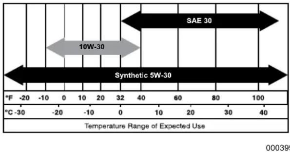
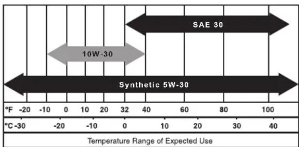
All oil should meet minimum American Petroleum Institute (API) Service Class SJ, SL or better. Use no special additives. Select the oil's viscosity grade according to the expected operating temperature (also see chart).
- Above 40^ F, use SAE 30
- Below 40^ F and down to 10^ F, use 10W-30
- All temperatures, use synthetic 5W-30
Use petroleum based oil for engine break-in before using synthetic oil.
CAUTION
Any attempt to crank or start the engine before adding the recom-
mended type and quantity of engine oil can result in engine damage.
Inspect engine oil level prior to each use, or every 8 hours of operation.
- Place generator on a level surface.
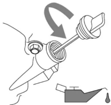
- Clean area around oil fill.
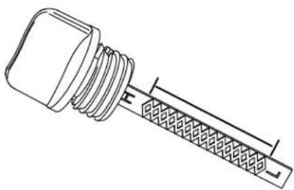
- Remove oil fill cap and wipe dipstick clean.

natural_image
Illustration of a hand holding a tool with a curved arrow indicating rotation (no text or symbols)000115
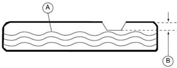
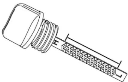
- Screw dipstick into filler neck. Verify oil level is within safe operating range as shown.
natural_image
Technical line drawing of a mechanical connector or connector assembly (no text or symbols)000116
- Add recommended engine oil as necessary.
- Replace oil fill cap and hand-tighten.
NOTICE: Some units have more than one oil fill location. It is only necessary to use one oil fill point.
Fuel
DANGER
Never fill fuel tank indoors. Never fill fuel tank when engine is running or
hot. Do not spill gasoline on a hot engine. Allow engine to cool before filling fuel tank.
DANGER
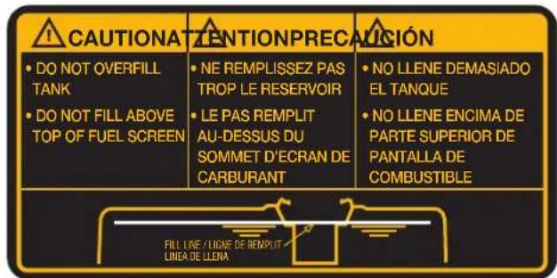
Do not overfill fuel tank. Always leave room for fuel expansion. If fuel tank is
overfilled, fuel can overflow onto a hot engine causing FIRE or EXPLOSION. Wipe up any spilled fuel immediately.
DANGER
Gasoline is highly FLAMMABLE and its vapors are EXPLOSIVE. Never
permit smoking, open flames, sparks or heat in the vicinity while handling gasoline.
Fuel requirements are as follows:
- Clean, fresh, unleaded gasoline.
• Minimum rating of 87 octane/87 AKI (91 RON). - Up to 10% ethanol (gasohol) is acceptable (where available; non-ethanol premium fuel is recommended).
• DO NOT use E85.
• DO NOT use a gas oil mix.
- DO NOT modify engine to run on alternate fuels. Stabilize fuel prior to storage.
- Verify unit is OFF and cooled for a minimum of two minutes prior to fueling.
- Place unit on level ground in a well ventilated area.
- Clean area around fuel cap and remove cap slowly.
- Slowly add recommended fuel (A). Do not fill above lip (B).
- Install fuel cap.
000400
NOTICE: Allow spilled fuel to evaporate before starting unit.
IMPORTANT: It is important to prevent gum deposits from forming in fuel system parts such as the carburetor, fuel hose or tank during storage. Alcohol-blended fuels (called gasohol, ethanol or methanol) can attract moisture, which leads to separation and formation of acids during storage. Acidic gas can damage the fuel system of an engine while in storage. To avoid engine problems, the fuel system should be emptied before storage of 30 days or longer. See the Storage section. Never use engine or carburetor cleaner products in the fuel tank as permanent damage may occur.
Starting Pull Start Engines
CAUTION
Equipment and property damage. Disconnect electrical loads prior to start-
ing or stopping unit. Failure to do so could result in equipment and property damage.
- Unplug all electrical loads from the unit's receptacles before starting engine.
- Place generator on a level surface.
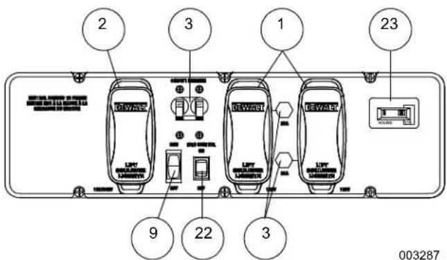
- Open the fuel shut-off valve (A).
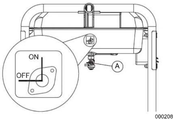
- Turn engine Run/Stop switch (B) to Run (manual start only).
DXGNR 6500
003287
DXGNR 8000
003606
- Slide engine choke (C) to Full Choke position (left).
- Firmly grasp recoil handle and pull slowly until increased resistance is felt. Pull rapidly up and away.
- When engine starts, move choke knob to 1/2-choke position until engine runs smoothly, then fully into Run position. If engine falters, move choke back to 1/2-choke position until engine runs smoothly, then to Run position.
- If engine fires, but does not continue to run, move choke lever to Full Choke and repeat starting instructions.
IMPORTANT: Do not overload the generator. Also, do not overload individual panel receptacles. These outlets are protected against overload with push-to-reset type circuit breakers. If amperage rating of any circuit breaker is exceeded, that breaker opens and electrical output to that receptacle is lost. Read "Don't Overload the Generator" carefully.
Starting Electric Start Engines
CAUTION
Equipment and property damage. Disconnect electrical loads prior to start-
ing or stopping unit. Failure to do so could result in equipment and property damage.
- Unplug all electrical loads from the unit's receptacles before starting the engine.
- Place generator on a level surface.
- Open the fuel shut-off valve.
- Move engine choke knob outward to Full Choke.
- Press and hold Start/Run/Stop switch in the Start position. When engine starts, release the switch to the Run position.
- When engine starts, move choke knob to 1/2 choke position until engine runs smoothly, then fully to RUN position. If engine falters, move choke knob back to 1/2 choke position until engine runs smoothly, then move to Run position.
Manual Start
The generator is equipped with a manual recoil starter which may be used if the battery is discharged. See Starting Pull Start Engines.
NOTICE:
The switch must be in the Run position. Use one of the generator's receptacle
outlets along with the included battery charger to charge the battery while the generator is running.
To start manually:
- Firmly grasp the recoil handle and pull slowly until increased resistance is felt.
- Pull rapidly up and away to start engine.
- Follow the same choke sequence.
NOTICE:
If engine fires, but does not continue to run, move choke lever to Full Choke and
repeat starting instructions.
IMPORTANT: Do not overload generator or individual panel receptacles. These outlets are overload protected with push-to-reset circuit breakers. If amperage rating of any circuit breaker is exceeded, that breaker opens and electrical output to that receptacle is lost. Read Know Generator Limits carefully.
Generator Shut Down
CAUTION
Equipment and property damage. Disconnect electrical loads prior to start-
ing or stopping unit. Failure to do so could result in equipment and property damage.
- Shut off all loads and unplug electrical loads from generator panel receptacles.
- Let engine run at no-load for several minutes to stabilize internal temperatures of engine and generator.
- Move Run/Stop switch to Stop.
- Close fuel valve.
NOTICE:
Under normal conditions, close fuel valve and allow generator to run carbure-
tor bowl out of fuel. For emergencies, switch to Stop.
Low Oil Level Shutdown System
The engine is equipped with a low oil level sensor that shuts down the engine automatically when the oil level drops below a specified level. The engine will not run until the oil has been filled to the proper level.
If the engine shuts down and there is sufficient fuel, check engine oil level.
Charging the Battery (electric start units only)
WARNING
Explosion. Batteries emit explosive gases while charging. Keep fire and
spark away. Wear protective gear when working with batteries. Failure to do so could cause death or serious injury.
WARNING
Risk of burns. Batteries contain sulfuric acid and can cause severe chemi-
cal burns. Wear protective gear when working with batteries. Failure to do so could cause death or serious injury.
NOTICE:
The battery shipped with the generator has been fully charged. A battery may
lose some of its charge when not in use for prolonged periods of time. If the battery is unable to crank the engine, plug in the 12V charger included in the accessory box. RUNNING THE GENERATOR DOES NOT CHARGE THE BATTERY.
Use battery charger plug to keep the battery charged and ready for use. Battery charging should be done in a dry location.
- Plug charger into Battery Charger Input jack, located on the control panel. Plug wall receptacle end of battery charger into 120 Volt AC wall outlet.
- Unplug battery charger from wall outlet and control panel jack when generator is to be in use.
NOTICE:
Do not use the battery charger for more than 48 hours at one charge.
BATTERY

000423
Maintenance
Maintenance Recommendations
Regular maintenance will improve performance and extend generator life. See a qualified dealer for service.
Generator warranty does not cover items subjected to operator abuse or negligence. To receive full warranty value, operator must maintain generator as instructed in this manual, including proper storage as detailed in Winter Storage and Long Term Storage.
NOTICE:
Call 1-888-431-6871 with questions about component replacement.
Maintenance Schedule
Follow maintenance schedule intervals, whichever occurs first according to use.
NOTICE:
Adverse conditions will require more frequent service.
NOTICE:
All required service and adjustments should be each season as detailed in the
following chart.
| Maintenance Task | As Needed | At Each Use | Every Season | Every 100 Hours | Every 200 Hours or Yearly |
| Clean Exterior Surfaces | X | ||||
| Check Engine Oil Level | X | ||||
| Clean Spark Arrestor | X | ||||
| Change Engine Oil * | X | X | |||
| Clean/Replace Air Filter ** | X | X | |||
| Replace Spark Plug | X | ||||
| Replace Fuel Filter | X | ||||
| Check/Adjust Valve Clearance *** | X |
* Change engine oil after first 30 hours of operation. Change every month when operating under heavy load or in high temperatures.
** Clean air filter more often under dirty or dusty conditions. Replace parts if they cannot be adequately cleaned.
*** Check valve clearance after first 50 hours of operation and adjust if necessary.
Product Specifications
| Generator Specifications | |
| Rated Power @ 1.0Power Factor | 6.5 / 8.0 kW** |
| Surge Power 8.125 / 10.0 kVA | |
| Rated AC Voltage 120/240 | |
| Rated AC Load (6.5 / 8.0)Current @ 240VCurrent @ 120V | 27.1 / 33.3 Amps**54.2 / 66.7 Amps** |
| Rated Frequency | 60 Hz @3600 RPM |
| Phase | Single Phase |
| Unit Weight65008000 | 75 kg (165 lb.)83 kg (183 lb.) |
| Unit Dimensions | L = 692mm (27.25") x W = 696mm (27.4") x H = 724mm (28.5") |
| ** Operating Temperature Range: -18 deg. C (0 deg. F) to 40 Deg. C (104 Deg. F). When operated above 25 deg. C (77 deg. F) there may be a decrease in power.** Maximum wattage and current are subject to, and limited by, such factors as fuel Btu content, ambient temperature, altitude, engine condition, etc. Maximum power decreases about 3.5% for each 1,000 feet above sea level; and will also decrease about 1% for each 6°C (10°F) above 16°C (60°F) ambient temperature. | |
| Engine Specifications | |
| Displacement (6.5 / 8.0) | 389cc / 420cc |
| Spark Plug Part Number | 0J00620106 |
| Spark Plug Type | F7TC |
| Spark Plug Gap | 0.028-0.031 inch or (0.70-0.80 mm) |
| Gasoline Capacity | 28.4 L (7.5 U.S. gallons) |
| Oil Type | See Chart in Before Starting Generator |
| Oil Capacity | 1.0 Liters (1.06 qt.) |
| Run Time (50% Load) (6.5 / 8.0) | 10 Hours / 9 Hours |
| Battery (if equipped) | 12 VDC, 10 Amp Hour |
Preventive Maintenance
Dirt or debris can cause improper operation and equipment damage. Clean generator daily or before each use. Keep area around and behind muffler free from combustible debris. Inspect all cooling air openings on generator.
WARNING
Do not insert any object through the air cooling slots. Generator can start
at any time and could result in death, serious injury and unit damage.
- Use a damp cloth to wipe exterior surfaces clean.
- Use a soft bristle brush to loosen caked on dirt, oil, etc.
- Use a vacuum to pick up loose dirt and debris.
- Low pressure air (not to exceed 25 psi) may be used to blow away dirt. Inspect cooling air slots and openings on generator. These openings must be kept clean and unobstructed.
NOTICE:
DO NOT use a garden hose to clean generator. Water can enter engine fuel
system and cause problems. If water enters generator through cooling air slots, some water will be retained in voids and crevices of rotor and stator winding insulation. Water and dirt buildup on generator internal windings will decrease insulation resistance of windings.
Engine Maintenance
WARNING
Accidental start-up. Disconnect spark plug wires when working on unit. Fail-
ure to do so could result in death or serious injury.
Engine Oil Recommendations
All oil should meet minimum American Petroleum Institute (API) Service Class SJ, SL or better. Use no special additives. Select the oil's viscosity grade according to the expected operating temperature (also see chart).
- Above 40^ F, use SAE 30
- Below 40^ F and down to 10^ F, use 10W-30
- All temperatures, use synthetic 5W-30
Use petroleum based oil for engine break-in (30 hours) before using synthetic oil.
000399
CAUTION
Any attempt to crank or start the engine before adding the recom-
mended type and quantity of engine oil can result in engine damage.
Inspect engine oil level prior to each use, or every 8 hours of operation.
- Place generator on a level surface.
- Clean area around oil fill.
- Remove oil fill cap and wipe dipstick clean.
natural_image
Illustration of a hand turning a tool with a valve, showing mechanical components and a water level (no text or symbols)000115
4. Screw dipstick into filler neck. Verify oil level is within safe operating range as shown.
natural_image
Technical line drawing of a mechanical connector or connector assembly (no text or symbols)000116
- Add recommended engine oil as necessary.
- Replace oil fill cap and hand-tighten.
NOTICE:
Some units have more than one oil fill location. It is only necessary to use one
oil fill point.
Change Engine Oil
WARNING
Accidental start-up. Disconnect spark plug wires when working on unit. Fail-
ure to do so could result in death or serious injury.
When using generator under extreme, dirty, dusty conditions, or in extremely hot weather, change oil more frequently.
NOTICE:
Don't pollute. Conserve resources. Return used oil to collection centers.
Change oil while engine is still warm from running, as follows:
- Place generator on a level surface.
- Disconnect the spark plug wire from the spark plug and place the wire where it cannot contact spark plug.
- Clean area around oil fill, and oil drain plug.
- Remove oil fill cap and wipe dipstick clean.
- Remove oil drain plug and drain oil completely into a suitable container.
- Install oil drain plug and tighten securely.
- Slowly pour oil into oil fill opening until oil level is between L and H marks on dipstick. DO NOT overfill.
- Install oil fill cap, and hand-tighten.
- Wipe up any spilled oil.
- Properly dispose of oil in accordance with all applicable regulations.
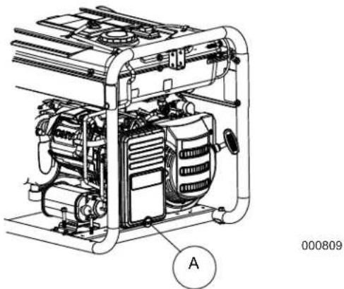
Air Filter
Engine will not run properly and may be damaged if run with a dirty air filter. Service air filter more frequently in dirty or dusty conditions.
To service air filter:
- Turn knob (A) and remove air filter cover.
- Wash in soapy water. Squeeze filter dry in clean cloth (DO NOT TWIST).
- Clean air filter cover before re-installing it.
NOTICE: To order a new air filter, contact the nearest authorized service center at 1-888-431-6871.
natural_image
Technical line drawing of a portable gas generator unit with labeled component A (no text or symbols beyond label)Service Spark Plug
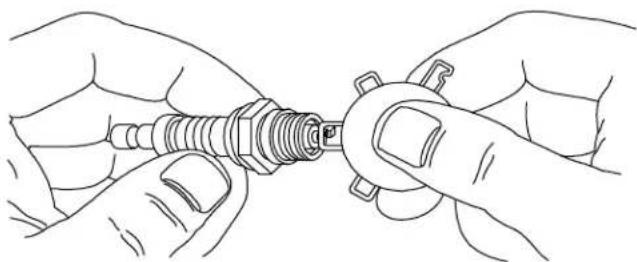
To service spark plug:
- Clean area around spark plug.
- Remove and inspect spark plug.
- Inspect electrode gap with wire feeler gauge and reset spark plug gap to 0.028 - 0.031 in (0.70 - 0.80 mm).
natural_image
Line drawing of two hands adjusting a screwdriver tip (no text or symbols)000211
NOTICE: Replace spark plug if electrodes are pitted, burned or porcelain is cracked. Use
ONLY recommended replacement plug. See Specifications.
- Install spark plug finger tight, and tighten an additional 3/8 to 1/2 turn using spark plug wrench.
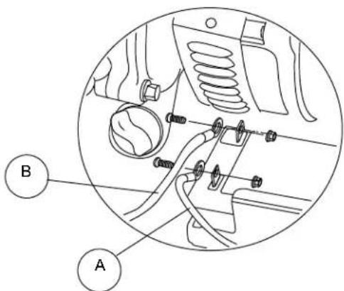
Battery Replacement/Connection (if equipped)
The battery shipped with the generator has been fully charged. A battery may lose some charge when not in use for prolonged periods of time. If battery is unable to crank engine, plug in the 12V charger included in the accessory box (see the Charging a Battery section).
IMPORTANT: RUNNING THE GENERATOR DOES NOT CHARGE BATTERY.
WARNING
Accidental Start-up. Disconnect the negative battery cable, then the posi-
tive battery cable when working on unit. Failure to do so could result in death or serious injury.
- Disconnect negative (-) battery terminal FIRST (A).
- Disconnect positive (+) battery terminal SECOND (B).
000224
- Install new battery. Install hold down bracket and tighten.
- Connect positive (+) battery terminal (B) FIRST (B). Slide rubber boot over connection hardware.
- Connect negative (-) battery terminal (A) SECOND.
- Slide rubber boot over connection hardware.
Valve Clearance
IMPORTANT: If uncomfortable about doing this procedure, or the proper tools are not available, take generator to the nearest service center to have valve clearance adjusted.
Check valve clearance after the first fifty-hours of operation. Adjust as necessary.
6500/8000
- Intake — 0.09 ± 0.02mm (cold), (0.004" ± 0.001" inches)
- Exhaust — 0.14 ± 0.02mm (cold) (0.006" ± 0.001" inches)
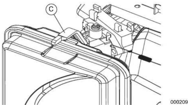
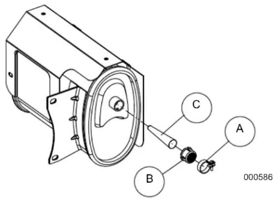
Inspect Spark Arrester Screen
WARNING
Hot Surfaces. When operating machine, do not touch hot surfaces.
Keep machine away from combustibles during use. Hot surfaces could result in severe burns or fire.
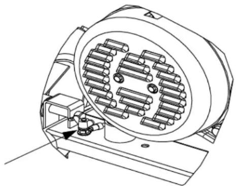
- Loosen clamp (A) and remove screw.
- Inspect screen (B) and replace if torn, perforated or otherwise damaged. If screen is not damaged, clean with commercial solvent.
- Replace spark arrestor cone (C) and screen (B). Secure with clamp and screw.
Storage
General
It is recommended to start and run the generator for 30 minutes, every 30 days. If this is not possible, refer to the following list to prepare unit for storage.
- DO NOT place a storage cover on a hot generator. Allow unit to cool to room temperature before storage.
- DO NOT store fuel from one season to another unless properly treated.
- Replace fuel container if rust is present. Rust in fuel will cause fuel system problems.
- Cover unit with a suitable protective, moisture resistant cover.
- Store unit in a clean and dry area.
- Always store generator and fuel away from heat and ignition sources.
Prepare Fuel System/Engine for Storage
Fuel stored over 30 days can go bad and damage fuel system components. Keep fuel fresh, use fuel stabilizer. If fuel stabilizer is added to fuel system, prepare and run engine for long term storage. Run engine for 10-15 minutes to circulate stabilizer throughout fuel system. Adequately prepared fuel can be stored up to 24 months.
NOTICE:
If fuel has not been treated with fuel stabilizer, it must be drained into an
approved container. Run engine until it stops from lack of fuel. Use of fuel stabilizer in fuel storage container is recommended to keep fuel fresh.
- Change engine oil.
- Remove spark plug.
- Pour tablespoon (5-10cc) of clean engine oil or spray a suitable fogging agent into cylinder.
WARNING
Vision Loss. Eye protection is required to avoid spray from spark
plug hole when cranking engine. Failure to do so could result in vision loss.
- Pull starter recoil several times to distribute oil in cylinder.
- Install spark plug.
- Pull recoil slowly until resistance is felt. This will close valves so moisture cannot enter engine cylinder. Gently release recoil.
Change Oil
Change engine oil before storage. See, subsection Change Engine Oil.
Troubleshooting
| PROBLEM CAUSE CORRECTION | ||
| Engine is running, but AC output is not available. | 1. Circuit breaker OPEN.2. Poor connection or defective cord set.3. Connected device is bad.4. Fault in generator.5. GFCI receptacle is OPEN (if equipped). | 1. Reset circuit breaker.2. Check and repair.3. Connect another device that is in good condition.4. Contact IASD.5. Correct ground fault and press reset button on GFCI receptacle (if equipped). |
| Engine runs well at no-load, but bogs when load is applied. | 1. Short circuit in a connected load.2. Generator is overloaded.3. Engine speed is too slow.4. Shorted generator circuit.5. Dirty fuel filter. | 1. Disconnect shorted electrical load.2. See Know Generator Limits.3. Contact IASD.4. Contact IASD.5. Replace fuel filter. |
| Engine will not start; or starts and runs rough. | 1. Fuel shut-off is OFF.2. Dirty air filter.3. Out of fuel.4. Stale fuel.5. Spark plug wire not connected to spark plug.6. Bad spark plug.7. Water in fuel.8. Overchoking.9. Low oil level.10. Excessive rich fuel mixture.11. Intake valve stuck open or closed.12. Engine lost compression.13. Dirty fuel filter. | 1. Turn fuel shut-off ON.2. Clean or replace air filter.3. Fill fuel tank.4. Drain fuel tank and fill with fresh fuel.5. Connect wire to spark plug.6. Replace spark plug.7. Drain fuel tank; fill with fresh fuel.8. Set choke to no choke position.9. Fill crankcase to correct level.10. Contact IASD.11. Contact IASD.12. Contact IASD.13. Replace fuel filter. |
| Engine shuts down during operation. | 1. Out of fuel.2. Low oil level.3. Fault in engine.4. CO PROTECT shut-off due to accumulating carbon monoxide if a RED light blinks on the side panel badge.5. CO PROTECT shut-off due to a system fault if a YELLOW light blinks on the side panel badge. | 1. Fill fuel tank.2. Fill crankcase to correct level.3. Contact IASD.4. Follow all Safety Instructions and relocate generator to an open area outside, far away from windows, doors and vents.5. Start to confirm YELLOW light blinks when/if generator shuts-off. If CO PROTECT continues to fault and shut-off, contact IASD. |
| Engine lacks power. 1. Load is too high. | 2. Dirty air filter.3. Engine needs to be serviced.4. Choke is partially closed.5. Dirty fuel filter.6. Spark arrestor clogged. | 1. Reduce load (see Know Generator Limits).2. Clean or replace air filter.3. Contact IASD.4. Set choke lever to no choke position.5. Replace fuel filter.6. Clean spark arrestor. |
| Engine surges or stumbles. 1. Choke | is opened too soon.2. Carburetor is running too rich or too lean.3. Dirty fuel filter. | 1. Set choke to halfway position until engine runs smoothly.2. Contact IASD.3. Replace fuel filter. |
| Engine starts and shuts off immediately. | 1. CO PROTECT shut-off due to accumulating carbon monoxide if a RED light blinks on the side panel badge.2. CO PROTECT shut-off due to a system fault if a YELLOW light blinks on the side panel badge. | 1. Follow all Safety Instructions and relocate generator to an open area outside, far away from windows, doors and vents.2. Start to confirm YELLOW light blinks when/if generator shuts-off. If CO PROTECT continues to fault and shut-off, contact IASD. |
DEWALT® is a registered trademark of DEWALT Industrial Tool Co., used under license.
The yellow/black color scheme is a trademark for DEWALT power tools and accessories.
Part No. 10000033366 Rev. D 09/11/2019
©2019 DEWALT
All rights reserved
Specifications are subject to change without notice.
No reproduction allowed in any form without prior written
consent from DEWALT
Product Manufactured by:
Generac Power Systems, Inc.
S45 W29290 Hwy. 59
Waukesha, WI 53189
natural_image
Technical line drawing of a portable gasifier with wheels and control panel (no text or symbols)Étiqueta de datos
000756
Reparaciones
DXGNR8000
natural_image
Pure diagram of rectangular shapes with no text, numbers, or symbols000203
Toma de corriente de 120/240 VCA, 30 Amp
natural_image
Circular diagram with concentric rings and three black curved segments arranged in a cross pattern (no text or symbols)000204
Interruptor de control de ralentí
natural_image
Technical line drawing of an electric motor with visible stator and rotor blades (no text or symbols)000227
natural_image
Illustration of a hand turning a valve with a curved arrow indicating rotation (no text or symbols)000115
natural_image
Technical line drawing of a connector with threaded end and internal spring-like structure (no text or symbols)000116
DXGNR 6500
003287
DXGNR 8000
003606
natural_image
Technical line drawing of a mechanical assembly with labeled component (C), no readable text or symbols presentnatural_image
Illustration of a hand holding a tool with a curved arrow indicating rotation (no text or symbols)000115
natural_image
Technical line drawing of a mechanical component with threaded end and textured base (no text or symbols)000116
natural_image
Technical line drawing of a portable gas generator unit with visible internal components and labeled component A (no text or symbols beyond label)000809
natural_image
Line drawing of two hands adjusting a screw component (no text or symbols)000211
AVISO:
000224
MANUEL D'INSTRUCTIONS
DEWALT®
natural_image
Technical line drawing of a portable gasifier with wheels and control panel (no text or symbols)DXGNR8000
natural_image
Pure electrical circuit lines without any symbols000203
Prise 120/240 V CA, 30 A
natural_image
Circular diagram with concentric rings and three black curved segments arranged in a cross pattern (no text or symbols)000204
natural_image
Technical line drawing of an electric motor with visible stator and rotor blades (no text or symbols)000227
natural_image
Illustration of a hand turning a valve with a water drop symbol (no text or labels)natural_image
Technical line drawing of a connector with threaded end and internal spring (no text or symbols)000116
DXGNR 6500
003287
natural_image
Illustration of a hand holding a tool with a curved arrow indicating rotation (no text or symbols)000115
natural_image
Technical line drawing of a mechanical component with threaded end and textured base (no text or symbols)000116
natural_image
Technical line drawing of a mechanical device with labeled component A (no text or symbols beyond label)000809
natural_image
Line drawing of hands connecting a screw to a nut (no text or symbols)088211
AVIS:
000224