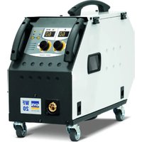
BMW C7502654 - Welding machine GYS - Free user manual and instructions
Find the device manual for free BMW C7502654 GYS in PDF.


User questions about BMW C7502654 GYS
0 question about this device. Answer the ones you know or ask your own.
Ask a new question about this device
Download the instructions for your Welding machine in PDF format for free! Find your manual BMW C7502654 - GYS and take your electronic device back in hand. On this page are published all the documents necessary for the use of your device. BMW C7502654 by GYS.
USER MANUAL BMW C7502654 GYS
natural_image
Technical line drawing of a mechanical device with articulated arms and wheels (no text or symbols)FR 2-17 / 18-38 / 99-108
EN 2-17 / 39-57 / 99-108
DE 2-17 / 58-77 / 99-108
ES 2-17 / 78-98 / 99-108
BMW C7502654 - GYSPOT PTI GENIUS
400 V
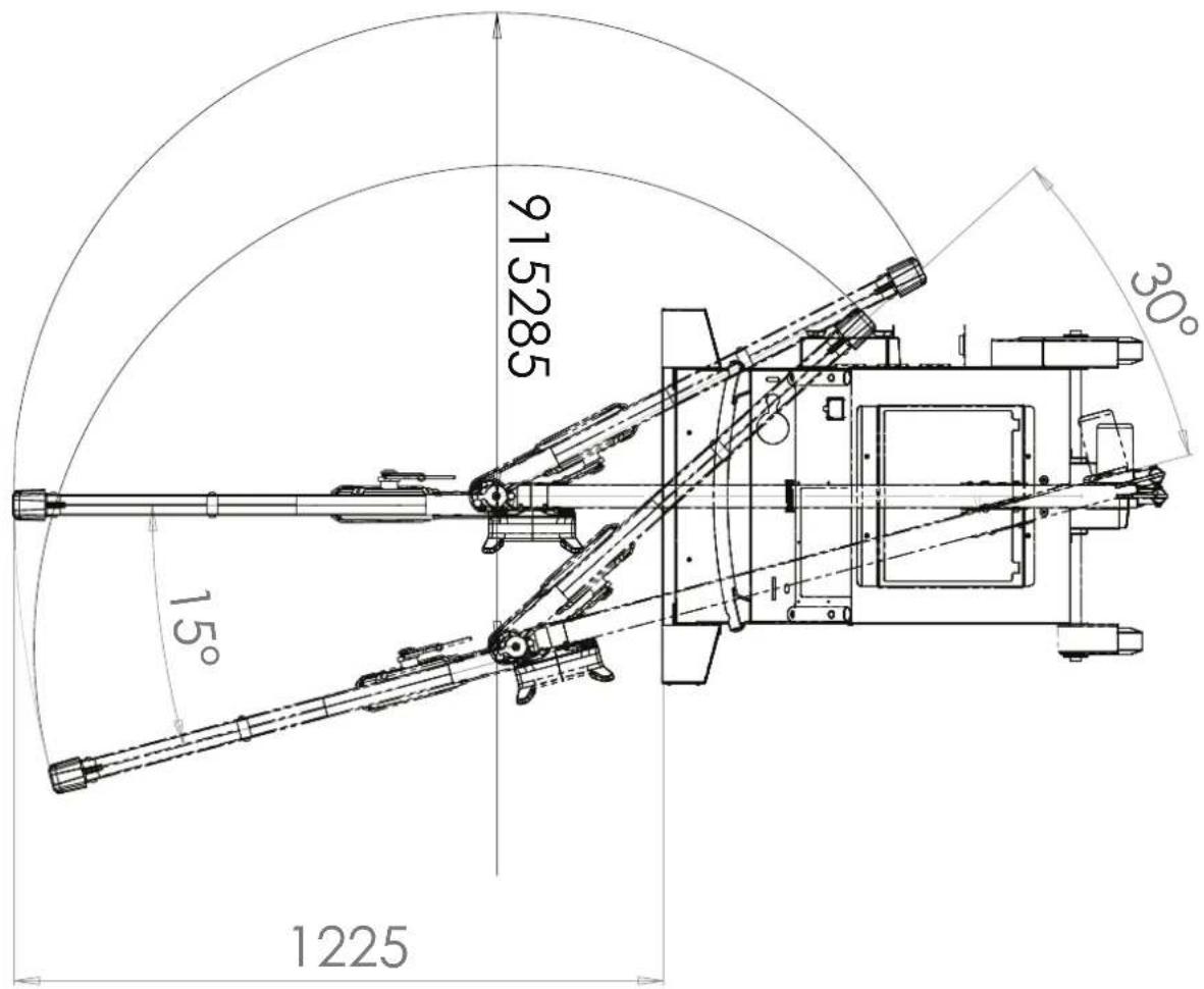
DIMENSIONS / ABMESSUNGEN / DIMENSIONES
text_image
915285 15° 1225 30°MONTAGE / ASSEMBLY / MONTAJE
text_image
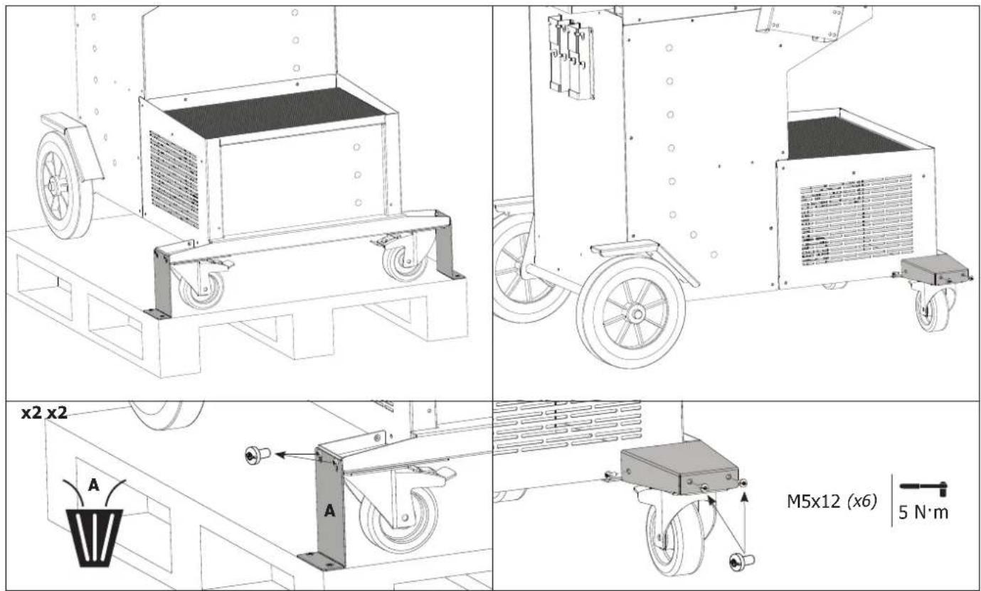
x2 x2 A A M5x12 (x6) 5 N·mMONTAGE SUPPORT PINCE EN G / ASSEMBLY OF G CLAMP SUPPORT / MONTAGE HALTERUNG «G» C-ZANGE / MONTAJE DEL SOPORTE DE PINZA EN G
text_image
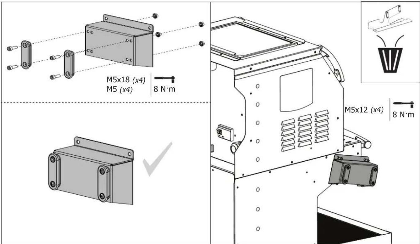
M5x18 (x4) M5 (x4) | 8 N·m M5x12 (x4) | 8 N·mMONTAGE SUPPORT BRAS G9 (OPTION) / G9 ARM SUPPORT MOUNTING (OPTIONAL) / G9 ARMSTÜTZMONTAGE (OPTIONAL) / G9 MONTAJE DEL SOPORTE DEL BRAZO (OPCIONAL)
MONTAGE SUPPORT BRAS / ARM SUPPORT MOUNTING / ARMSTÜTZMONTAGE / MONTAJE DEL SOPORTE DEL BRAZO
text_image
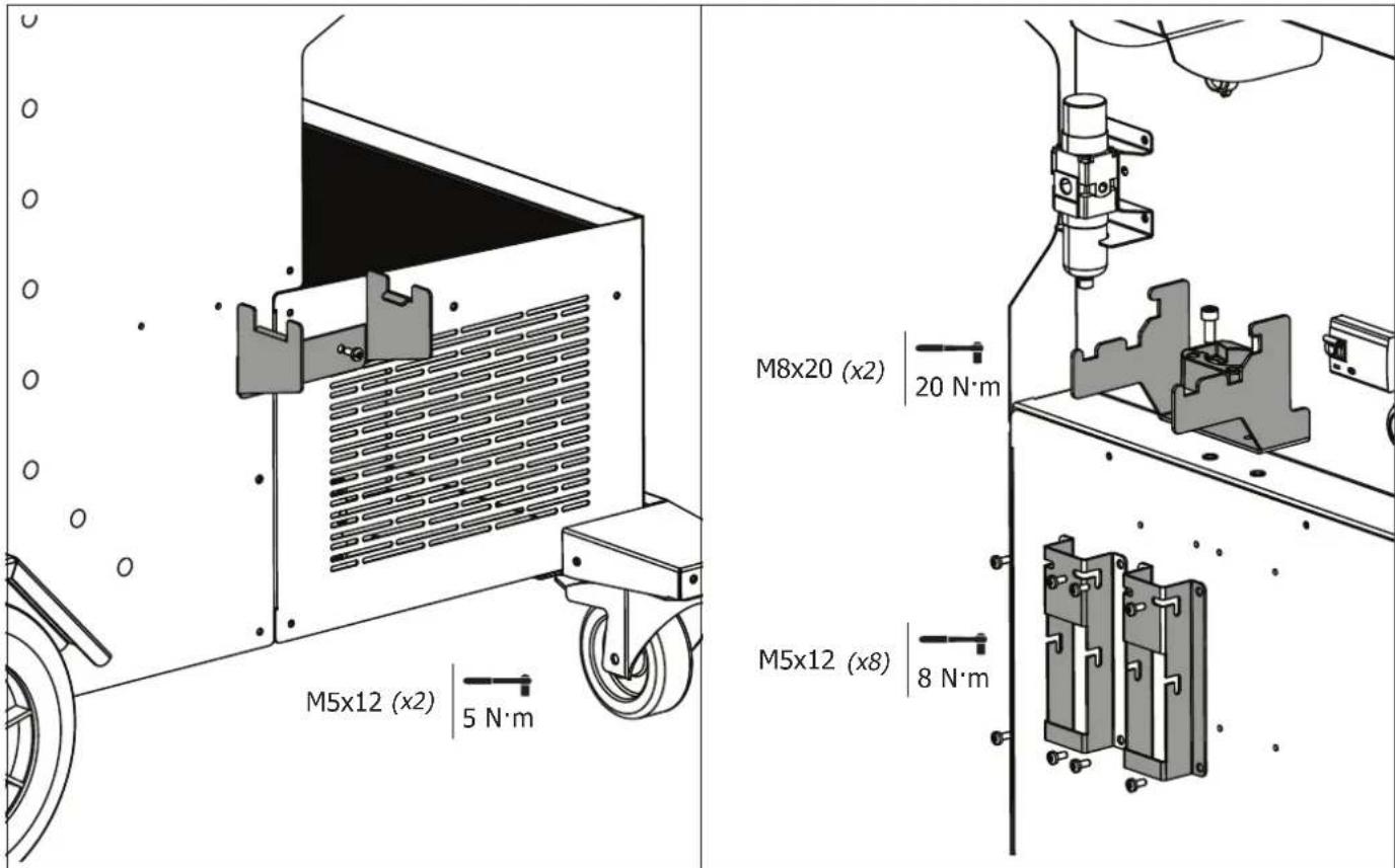
M5x12 (x2) | 5 N·m M8x20 (x2) | 20 N·m M5x12 (x8) | 8 N·mMONTAGE POTENCE / ASSEMBLY OF OVERHANGING ARM / MONTAGE AUSLEGER / ENSAMBLAJE DEL SOPORTE

The use of the bracket is strictly reserved to relieve the weight of the welding tongs. It must never be used for lifting or any other application, otherwise the jib crane trolley assembly may overturn.
text_image
M5x12 (x4) | 4 N·m2
text_image
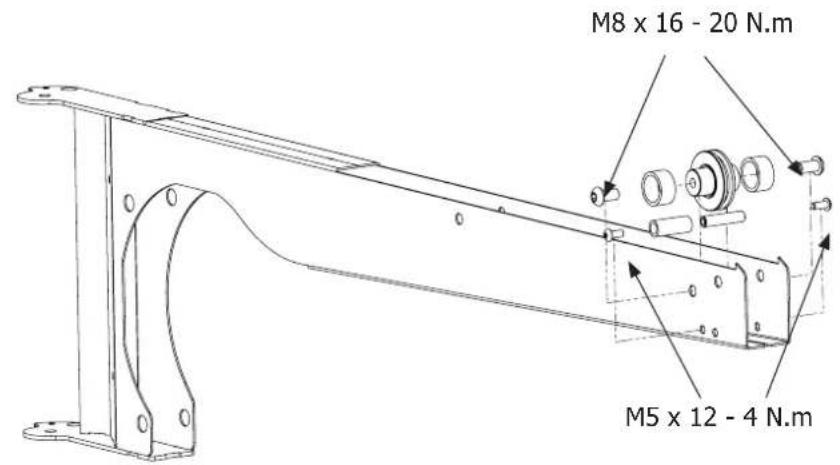
M8 x 16 - 20 N.m M5 x 12 - 4 N.mM8x16 (x2)
M5x12 (x2)

20 N.m
4 N.m
3
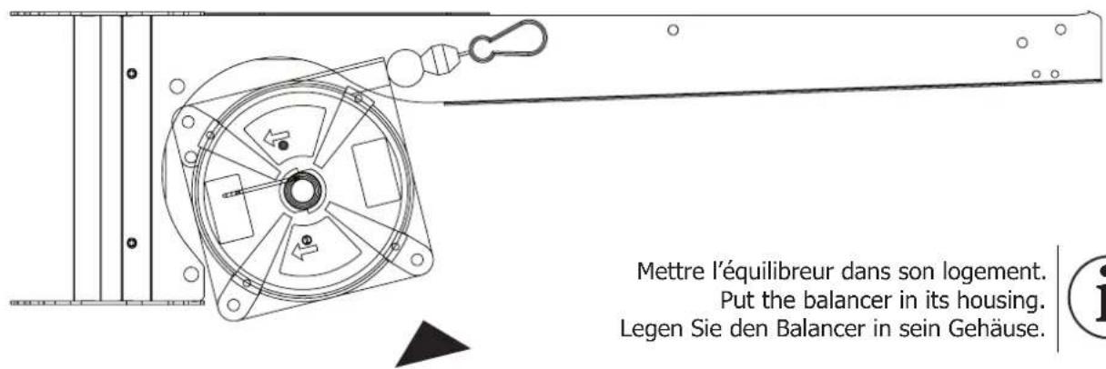
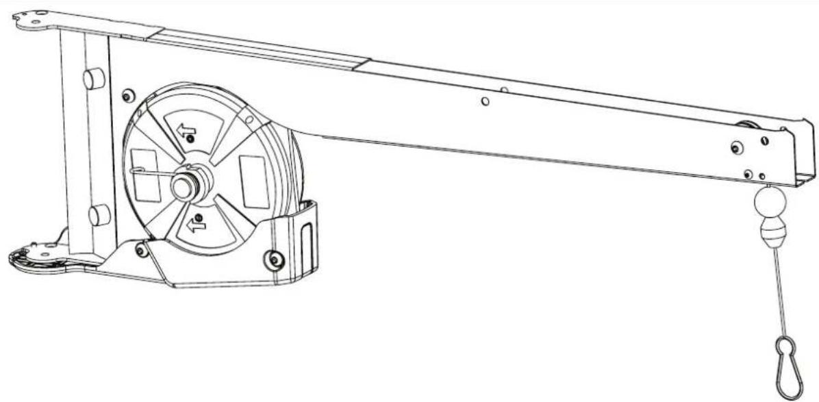
Pull the balancer cable through the pulley and the notch.
natural_image
Technical line drawing of a mechanical lever system with pulley and rotating components (no text or symbols)7
natural_image
Technical line drawing of a mechanical lifting device with levers and gears (no text or symbols)8
M8x16 (x4)

M5x12 (x2)
20 N·m
4 N.m
text_image
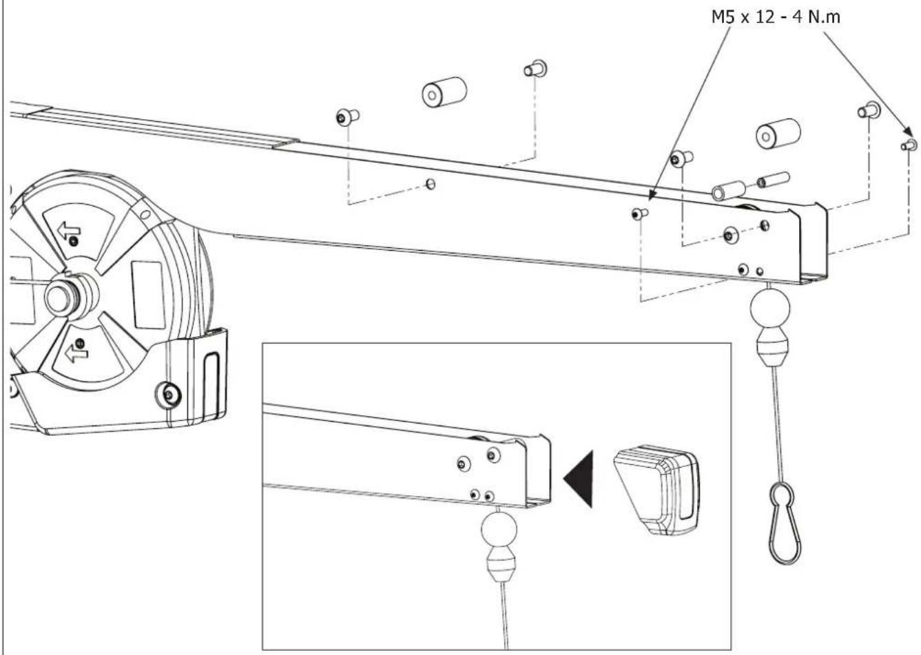
M5 x 12 - 4 N.m9
natural_image
Technical line drawing of an industrial control box with internal components and mounting features (no text or symbols)10
natural_image
Line drawing of a mechanical cart with wheels and a closed lid, no text or symbols present11
natural_image
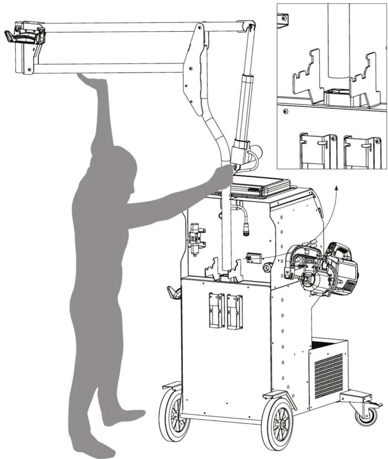
Technical line drawing of a robotic industrial machine with a human silhouette and inset detail view (no text or symbols)

Do not underestimate the weight of the overhanging arm (17.4 kg)!
In order to assemble or disassemble the overhanging arm smoothly and easily, 2 people are required.
natural_image
Technical line drawing of a mobile industrial machine with attached boom, showing internal components and assembly (no text or symbols)13
Swivel the bracket until the screw fits into the recess.
natural_image
Technical line drawing of a mechanical assembly with pipes and components, no visible text or symbols14
Lock the gallows by fixing the bracket.
natural_image
Technical line drawing of a mechanical assembly with pipes and components (no text or symbols)15
Connect the cylinder connector to the carriage.
Press the button to put the stem in the down position.
natural_image
Technical line drawing of a mechanical device with attached crane and motor assembly, showing front and side views (no text or symbols)Adjust the hardness of the moving part by tightening the nut with the key provided.
natural_image
Technical line drawing of a mechanical assembly with a rotating component (no text or symbols)BMW C7502654 - GYSPOT PTI GENIUS
17
To adjust the tension of the balancer cable, the user must load the clamp on the cable.
- It is possible to position a blocking device on the balancer cable, by shifting the part below along the cable. Unscrew the 2 screws, move the part and screw it back to the desired height.
- by positioning this locking system 50-60 cm from the clamp, the clamp can be unhooked without having to position it on the machine's clamp holder.
natural_image
Technical line drawing of a mechanical device with no visible text or symbolsFIG-1
text_image
Rangement électrodes Electrode storage Elektrodenaufbewahrung ① ② ③ ④ ⑤ ⑥ ⑦ ⑧ ⑨FIG-2
text_image
Technical diagram of a mechanical device with numbered parts for identification and assembly reference.AVERTISSEMENTS - RÈGLES DE SÉCURITÉ
CONSIGNE GÉNÉRALE

text_image
A F A F A Anatural_image
Two-panel image showing a black fabric sleeve being held, with checkmark and cross symbols indicating correct and incorrect states (no text or symbols on the fabric itself)INSTALLATION - FONCTIONNEMENT PRODUIT
 G1 (550 daN) - ref. 022768 INCLUS G1 (550 daN) - ref. 022768 INCLUS | 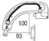 G2 (300 daN) - ref. 022775 G2 (300 daN) - ref. 022775 | 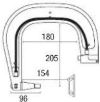 G3 (550 daN) - ref. 022782 G3 (550 daN) - ref. 022782 | 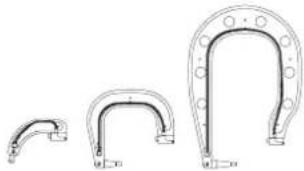 G2 + G3 + G4 - ref. 022898 G2 + G3 + G4 - ref. 022898 | |
 G4 (550 daN) - ref. 022799 G4 (550 daN) - ref. 022799 | 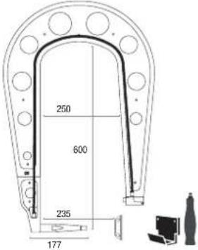 G5 (550 daN) (6.25 kg) - ref. 022805G10 (400 daN) (5 kg) - ref. 067165 G5 (550 daN) (6.25 kg) - ref. 022805G10 (400 daN) (5 kg) - ref. 067165 | 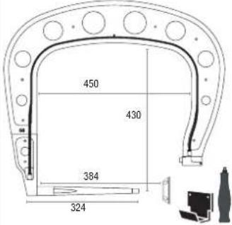 G8 (550 daN) - ref. 022836 G8 (550 daN) - ref. 022836 | 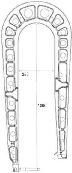 | |
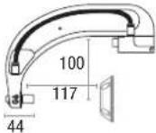 G6 (550 daN) - ref. 022812 G6 (550 daN) - ref. 022812 | 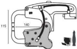 G9 + X1 (550 daN) - ref. 022881 - X1 (550 daN) - ref. 050501 G9 + X1 (550 daN) - ref. 022881 - X1 (550 daN) - ref. 050501 | G12 (550 daN) - ref. 075238 | ||
ALIMENTATION
INTERFACE HOMME MACHINE
text_image
MODE NORMAL 10/02/08 - 14h30 ① → ESC : PRESS 2s 1.0 mm THLE C5 200mm ⑤ ⑥ ⑦ REPORTING MOSK MEMORY① Touche
text_image
MODE MANUEL 04-04-10 2015 I 6.6 kA T 310 m F 195 delt G1 100mm Pressure 6.75artext_image
NODE ENERGY ETALONNAGE A VIDE I --- kA E --- kWs ΔZ 0 Ω G1 100mm Passive 4.35artext_image
04/04/12-03:16 Surchauffetext_image
ERROR 128 15/01/2021 09:27 STOP Pump priming defecttext_image
Immaterculation OKtext_image
CATALOGUE JOB1 JOB 2 JOB 3 JOB 4 JOB 5 JOB 6text_image
Technical diagram showing mechanical assembly with numbered components, likely for assembly or maintenance instructions.SUR-OUVERTURE MÉCANIQUE DU BRAS
text_image
Technical diagram showing mechanical assembly with numbered components and labeled partsVERROUILLAGE/DÉVERROUILLAGE DU GYROSCOPE
ANOMALIES, CAUSES, REMEDES
Read and understand the following safety instructions before use. Any modification or updates that are not specified in the instructions manual should not be undertaken. Please store this manual safely.
The manufacturer is not liable for any injury or damage due to a non-compliance with the instructions featured in this manual.
In the event of problems or uncertainties, please consult a qualified person to handle the installation properly. The instructions cover the material in the condition it was delivered. It is the responsibility of the user to analyse the risks taken when not following the instructions published by GYS.
ENVIRONMENT
This equipment must only be used for welding operations in accordance with the limits indicated on the descriptive panel and/or in the user manual. Safety instructions must be followed. In case of improper or unsafe use, the manufacturer cannot be held liable.
This equipment must be used and stored in a room free from dust, acid, flammable gas or any other corrosive agent. Operate the machine in an open, or well-ventilated area.
Operating temperature:
Use between +5°C at +40°C (+41°F at +104°F).
Storage between -25°C at +55°C (-13°F at 131°F).
Air humidity:
Lower or equal to 50% at 40°C (104°F).
Lower or equal to 90% at 20°C (68°F).
Altitude : Up to 1000 m above sea level (3280 feet).
INDIVIDUAL PROTECTION & OTHERS
Resistance welding can be dangerous and cause serious injuries or even death. It needs to be used by a qualified technician with training relevant to the machine.
Welding exposes the user to dangerous heat, arc rays, electromagnetic fields, risk of electric shock, noise and gas fumes. People wearing pacemakers are advised to consult a doctor before using the welding machine.
To protect oneself as well as others, ensure the following safety precautions are taken:

In order to protect you from burns and radiations, wear clothing without turn-up or cuffs. These clothes must be insulating, dry, fireproof, in good condition and cover the whole body.

Wear protective gloves which guarantee electrical and thermal insulation.

Use sufficient welding protective gear for the whole body: hood, gloves, jacket, trousers... (varies depending on the application/operation). Protect the eyes during cleaning operations. Contact lenses are prohibited during use.
It may be necessary to install fireproof welding curtains to protect others against arc rays, weld spatters and sparks.
Ask people around the working area to look away from at the arc or the molten metal, and to wear protective clothing.

Ensure ear protection is worn by the operator if the work exceeds the authorised noise limit (the same applies to any person in the welding area).
Keep mobile parts at a distance (fan, electrodes...) from hands, hair and clothing.
Never remove the safety covers from the cooling unit when the machine is plugged in. The manufacturer is not liable for any injury or damage caused due to non-compliance with the safety precautions.

Parts that have just been welded will be hot and may cause burns when touched. During maintenance work on the torch or the electrode holder, you should make sure it's cold enough and wait at least 10 minutes before any intervention. When using a water-cooled torch, make sure that the cooling unit is switched on to avoid any burns caused by the liquid.
It is important to secure the working area before leaving it to ensure protection of the goods and the safety of people.
WELDING FUMES AND GASES

Fumes, gas and dust produced during welding are hazardous to health. It is mandatory to ensure adequate ventilation and/or extraction to keep fumes and gas away from the work area. Using an air fed welding helmet is recommended in case of insufficient ventilation in the workplace.
Check that the air supply is effective by referring to the recommended safety regulations.
Precautions must be taken when welding in small areas, and the operator will need supervision from a safe distance. Welding certain pieces of metal containing lead, cadmium, zinc, mercury or beryllium can be extremely toxic. The user will also need to degrease the workpiece before welding. Gas cylinders must be stored in an open or ventilated area. They must be stored vertically and held by a support or trolley to limit the risk of fall. Do not weld in areas where grease or paint are stored.
FIRE AND EXPLOSION RISKS

Protect the entire welding area. Flammable materials must be moved to a minimum safe distance of 11 meters. A fire extinguisher must be readily available near the welding operations.
Be careful of weld spatter and sparks, even through cracks. If not careful then this could potentially lead to a fire or an explosion. Keep people, flammable materials/objects and containers that are under pressure at a safe distance.
Welding in closed containers or pipes should be avoided and, if they are opened, they must be emptied of any flammable or explosive material (oil, fuel, gas ...).
Grinding operations should not be carried out close to the power supply or any flammable materials.
ELECTRICAL SAFETY

The electrical mains used must have an earth terminal. An electric shock could cause serious injuries or potentially even deadly accidents.
Never make contact with live parts inside or outside the current source (cables, electrodes, arms, guns...) as they are connected to the welding circuit. Before opening the device, it is imperative to disconnect it from the mains and wait 2 minutes, so that all the capacitors are discharged.
Damaged cables and torches must be changed by a qualified and skilled professional. Make sure that the cable cross section is adequate with the usage (extensions and welding cables). Always wear dry clothes which are in good condition in order to be isolated from the welding circuit. Wear insulating shoes, regardless of the workplace/environment in which you work in.

Warning! Very hot surface. Risk of burns.
- The parts and pieces that have just been heated are hot and may cause burns when manipulated.
- Do not touch any hot parts with your hands.
- Wait for the parts and pieces to cool down before handling them.
- In case of burn, rinse thoroughly with water and consult a doctor as soon as possible.
EMC MATERIAL CLASSIFICATION

This Class A machine is not intended to be used on a residential site where the electric current is supplied by the domestic low-voltage power grid. There may be issues in ensuring electromagnetic compatibility on these sort of sites, due to conducted interferences as well as radiation.

This equipment does not comply with IEC 61000-3-12 and is intended to be connected to private low-voltage systems interfacing with the public power grid only at the medium- or high-voltage level. If connected to a public low-voltage power grid, the installer or user of the machine has to ensure, by checking with the network operator, that the device can be connected.
ELECTROMAGNETIC INTERFERENCES
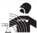
The electric current flowing through any conductor causes electrical and magnetic fields (EMF). The welding current generates an EMF around the welding circuit and the welding equipment.
The EMF electromagnetic fields can interfere with certain medical implants, such as pacemakers. Protective measures must be taken for people having medical implants. For example, by restricting access to passers-by or conducting an individual risk evaluation for the welders.
All welders should take the following precautions in order to minimise exposure to the electromagnetic fields (EMF) generated by the welding circuit:
- position the welding cables together – if possible, attach them;
- keep your head and upper body as far as possible from the welding circuit;
- never wrap the cables around your body;
- never position your body between the welding cables. Hold both welding cables on the same side of your body;
- connect the earth clamp as close as possible to the welding area;
- do not work too close to, do not lean and do not sit on the welding machine
- do not weld when transporting the welding machine or its wire feeder.

People wearing pacemakers are advised to consult their doctor before using this device.
Exposure to electromagnetic fields while welding may have other health effects which are not yet identified.
RECOMMENDATIONS FOR WELDING AREA ASSESSMENT AND WELDING
Miscellaneous
The user is responsible for the correct installation and usage of the welding material based on the instructions supplied by the manufacturer. If electromagnetic disturbances are detected, it is the user's responsibility to resolve the situation with the manufacturer's technical assistance. In some cases, this corrective action may be as simple as earthing the welding circuit. In other cases, it may be necessary to construct an electromagnetic shield around the welding power source and around the entire piece by fitting input filters. In all cases, electromagnetic interferences must be reduced until they are no longer inconvenient.
Welding area assessment
Before installing the machine, the user must evaluate the possible electromagnetic problems that may arise in the area where the installation is planned. The following must be taken into account:
a) the presence (above, below and next to the arc welding machine) of other power cables, remote cables and telephone cables;
b) television transmitters and receivers;
c) computers and other hardware;
d) critical safety equipment such as industrial machine protections;
e) the health and safety of people in the area especially if they are using pacemakers or hearing aids;
f) calibration and measuring equipment;
g) the isolation of other pieces of equipment which are in the same area.
The operator has to ensure that the devices and equipment used in the same area are compatible with each other. This may require extra precautions;
h) the time of day during the welding or other activities have to be performed.
The dimension of the cutting area that has to be considered depends on the size and shape of the building and the type of work undertaken. The area taken into consideration might go beyond the limits of the installations.
Review of the welding installation
Reviewing the welding installations can be useful to determine and resolve any case of electrical disturbances. The assessment of emissions must include in situ measurements as specified in Article 10 of CISPR 11: 2009. In situ measurements can also be used to confirm the effectiveness of mitigation measures.
RECOMMENDAED METHODS TO REDUCE ELECTROMAGNETIC EMISSIONS
a. National power grid: The arc welding machine must be connected to the national power grid in accordance with the manufacturer's recommendation. In case of interferences, it may be necessary to take additional precautions such as the filtering of the power supply network. Consideration should be given to shielding the power supply cable in a metal conduit or equivalent of permanently installed arc welding equipment. It is necessary to ensure the electrical continuity of the frame along its entire length. The shielding should be connected to the welding current source to ensure a good electrical contact between the conduit and the casing of the welding current source.
b. Maintenance of the resistance welding equipment: The resistance welding machine should be subject to a routine maintenance check in line with the recommendations of the manufacturer. All accesses, service doors and covers should be closed and properly locked when the arc welding equipment is on. The arc welding equipment must not be modified in any way, except for the changes and settings covered in the instructions.
c. Welding cables: Cables must be as short as possible, close to each other and close to the ground, if not on the ground.
d. Equipotential bonding: consideration should be given to bond all metal objects in the surrounding area. However, metal objects connected to the workpiece increase the risk of electric shock if the operator touches both these metal elements and the electrode. It is necessary to insulate the operator from such metal objects.
e. Earthing of the welded part: When the part is not earthed - due to electrical safety reasons or because of its size or location (which is the case with ship hulls or metallic building structures), the earthing of the part can, in some cases but not systematically, reduce emissions It is preferable to avoid the earthing of parts that could increase the risk of injury to the users or damage other electrical equipment. If necessary, it is appropriate that the earthing of the part is done directly, but the safety rules in some countries may not allow such a direct connection and it is appropriate that the connection is made using a capacitor selected according to national regulations.
f. Protection and shielding: The selective protection and shielding of other cables and devices in the area can reduce perturbation issues. The protection of the entire welding area can be considered for specific situations.
TRANSPORT AND TRANSIT OF THE WELDING MACHINE

The top of the machine is equipped with handles for movement by hand. Be careful not to underestimate the weight of the machine. The handles cannot be used to lift the product.
Do not use the cables or torch to move the machine. Do not place/carry the unit over people or objects.
EQUIPMENT INSTALLATION
- Put the machine on the floor (maximum incline of 10^ ).
- The machine must be placed in a sheltered area away from rain or direct sunlight.
• The machine protection level is IP20, which means : - Protection against access to dangerous parts from solid bodies of a diameter ≥12.5mm and,
- Protection against water projections.
Power cables, extension leads and welding cables must be fully uncoiled to prevent overheating.

The manufacturer does not accept any liability in relation to damages caused to objects or harm caused to persons as the result of incorrect and/or dangerous use of the machine.
MAINTENANCE / RECOMMENDATIONS
- The operators must have received suitable training in order to use the machine at its maximum potential and weld correctly.
- Check which welding process is authorised by the manufacturer before attempting any vehicle repair.

The maintenance and repair of the machine can only be undertaken by the manufacturer. Any work undertaken by a third party on the machine will invalidate the warranty. The manufacturer will not accept liability in the event of an incident that would occur after this work was undertaken.
Ensure the machine is unplugged from the mains, and then wait 2 minutes before carrying out maintenance work. Inside the machine, voltage and current levels are high and dangerous.
- Prior to any work on the machine, turn the air supply off and depressurise the circuit of the machine.
- Make sure to purge the filter of the dehumidifier located at the back of the machine regularly.
- The device is fitted with a balance system designed for easier handling. However, it is not recommended to leave the clamp hanging at the end of the cable of the balancing system for prolonged periods of time as it might increase wear. Do not drop the clamp repetitively or it might damage the balancing system.
- It is possible to adjust the tension of the balancing system spring using the spanner provided.
- The level of the cooling liquid is important for the machine to work correctly. It must always be between the «minimum» and «maximum» marks on the machine. Regularly check the level and top-up when needed.
- It is recommended to renew the cooling liquid every 2 years.
-
All the welding tools will wear off with use. Ensure that these tools are clean to get the best results.
-
Prior to using the pneumatic clamp, check the condition of the electrodes/caps (regardless if they are round or flat). If that is not the case, clean them using sand paper (thin grain) or replace them (see explanation on the machine).
- To ensure an efficient welding spot, it is necessary to replace the caps every 200 spots.
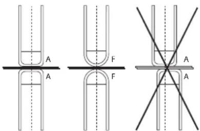
Warning : the caps must be perfectly aligned. If this is not the case, check the alignment of the electrodes (cf. chapter «Assembly and replacement of the arms» P. 48)
text_image
A F A F A A- Prior to using the gun, check the condition of the different tools (star, single sided electrode, carbon electrode...) and clean or replace if required.
- Remove regularly the casing and any excess of dust. Take this opportunity to have the electrical connections checked by a qualified person, with an insulated tool.
- Regularly review the condition of the power cable and welding connection cables. In case of visible signs of damage, organise for them to be replaced by the manufacturer or a qualified technician.

After each use make sure that the harness is not left twisted. A constantly twisted harness leads to its premature deterioration and can present an electrical hazard to the user.
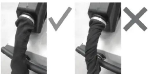
natural_image
Two black-and-white photos showing a belt buckle being held, with checkmark and cross symbols indicating correct and incorrect states (no text or symbols present)- Ensure the vents of the device are not blocked to allow adequate air circulation.
USE OF THE GALLOWS
- The operator must properly fill the coolant canister with coolant before use.
- The use of the bracket is strictly reserved to support the clamp during welding operations.
- Under no circumstances must the jib crane be used as a lifting or other means, as there is a risk of tipping the jib crane trolley assembly.
INSTALLATION – PRODUCT OPERATION
Only qualified personnel authorised by the manufacturer should perform the installation of the welding equipment. During the installation, the operator must ensure that the machine is disconnected from the mains. Connecting generators in serial or in parallel is forbidden.
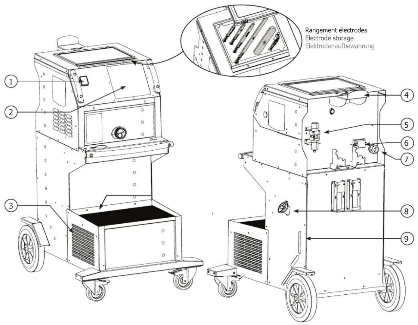
EQUIPMENT DESCRIPTION (FIG-1)
This machine is designed to carry out the car body repair operations described below :
- spot welding on sheets using a pneumatic clamp,
- welding of sheets using a gun,
- welding of nails, rivets, washers, studs, mouldings,
- repair of bumps and impacts (hail impacts with the pliers option).
1- SD card reader 6- Power-on circuit breaker
2- Interface (MMI) 7- Power cord
3- Cooling unit 8- Filling cap
4- Overhanging arm locking support 9- Cooling liquid gauge
5- Regulator
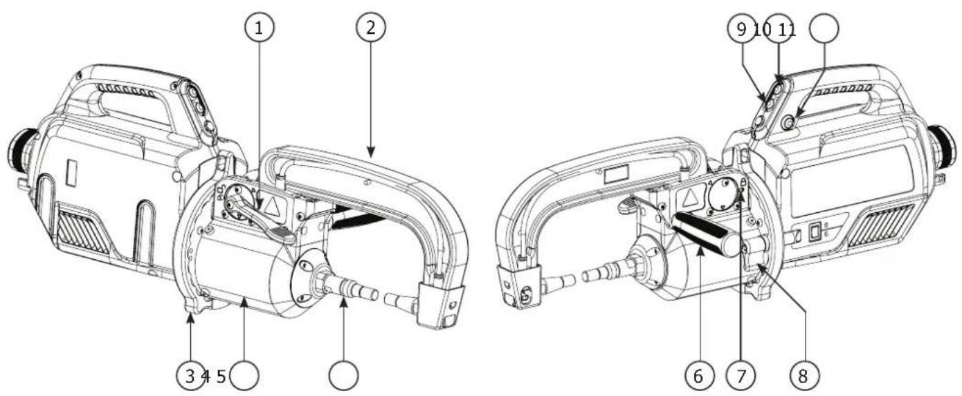
DESCRIPTION OF THE G CLAMP (FIG-2)
1- Arm locking/unlocking lever 7- Locking latch
2- Interchangeable arm 8- Gyro lock/unlock mechanism
3- Gyroscope 9- Over-opening button
4- Pneumatic body 10- Spot welding button
5- Over-opening electrode 11- Remote settings button
6- Side handle 12- Stem height control lever
Clamp opening : push the button (FIG 2 - 10), the opening of the clamp can be released. The electrode retracts in the clamp leaving a space of 80 mm to access the welding area instead of 20 mm when not in use.
ACCESSORIES AND OPTIONS
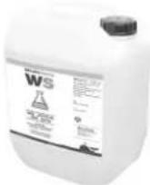 | 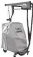 | 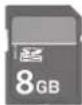 | 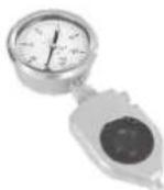 |
| Coolant Protective cover5 l: 06251110 l: 052246 | 077126 | SD card including automatic programs INCLUDED050914 | Pressure sensor052314 |
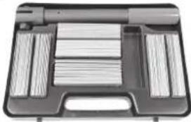 | 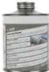 |  |   |
| Welding test case050433 | ANTI-CORROSION WELDING PRIMER 500ml076822 | Kit remove wifi070691 | BMW - 6 CAPS TYPE A-32 - ∅ 16mm085664 |
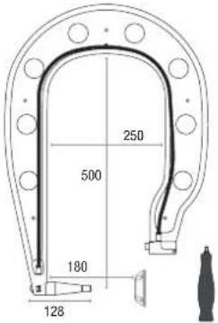
These optional arms are supplied with 13mm caps.
For the BMW / MINI repair, the caps must be replaced by the type A-32 - ∅16mm caps - Ref. 085664.
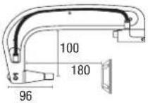
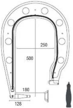
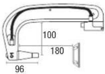 G1 (550 daN) - ref. 022768 INCLUS G1 (550 daN) - ref. 022768 INCLUS | 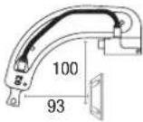 G2 (300 daN) - ref. 022775 G2 (300 daN) - ref. 022775 | 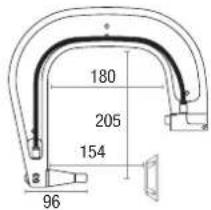 G3 (550 daN) - ref. 022782 G3 (550 daN) - ref. 022782 | 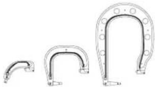 G2 + G3 + G4 - ref. 022898 G2 + G3 + G4 - ref. 022898 | |
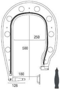 G4 (550 daN) - ref. 022799 G4 (550 daN) - ref. 022799 | 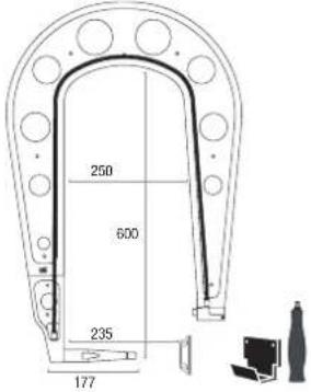 G5 (550 daN) (6.25 kg) - ref. 022805G10 (400 daN) (5 kg) - ref. 067165 G5 (550 daN) (6.25 kg) - ref. 022805G10 (400 daN) (5 kg) - ref. 067165 | 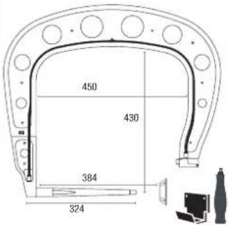 G8 (550 daN) - ref. 022836 G8 (550 daN) - ref. 022836 | 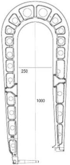 | |
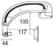 G6 (550 daN) - ref. 022812 G6 (550 daN) - ref. 022812 | 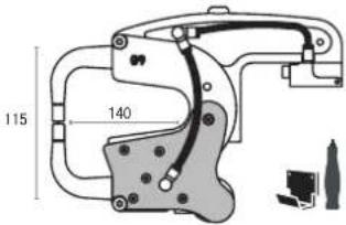 G9 + X1 (550 daN) - ref. 022881 - X1 (550 daN) - ref. 050501 G9 + X1 (550 daN) - ref. 022881 - X1 (550 daN) - ref. 050501 | G12 (550 daN) - ref. 075238 | ||
G6 (550 daN) - ref. 022812
G9 + X1 (550 daN) - ref. 022881 - X1 (550 daN) - ref. 050501
G12 (550 daN) - ref. 075238
POWER SUPPLY
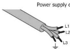
- This material is designed to be powered by a 3-phase 400V power supply only (50-60 Hz) with four wires with a neutral one connected to the earth and fitted with a ≥ 25 A D-rated circuit breaker (or aM type fuse).
The permanent current absorbed (I1p or ILp) displayed in the section «technical specifications» of this manual relates to use at maximum power. Check that the power supply and its protection (fuse and/or circuit breaker) are compatible with the current needed by the machine. In some countries, it may be necessary to change the plug to allow the use at maximum settings.
• Power supply recommendations :
In order to limit the voltage drop in the power supply line and to avoid any risk of disconnection of the protection, it is imperative to connect the equipment to a «dedicated» socket. This plug must be connected to the electrical panel and only power this equipment.
Check the cross-section of the cable reaching the connection socket: 4 × 6 mm^2 . If the power line from the switchboard is longer than 10 m, use a conductor cross-section of 10 mm^2 . If you are using an extension cable, use a conductor cross-section of 6 mm^2 ( 10 mm^2 if the length of the line + extension > 10m).
text_image
Power supply c L1 L2 L3Plug 400 V / 3 phases + earth
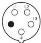
● Neutral (not used)
- The device turns into protection mode if the power supply tension is below or above the 15% or in the case of no phase. To indicate this default, the screen displays an error code.
- In order to ensure optimal functioning of the equipment, check that the compressed air circuit can supply 8 bar (116 Psi) and then connect the air supply to the back of the machine. The machine must not be used on an air network with a pressure under 4 bar (58 Psi) or over 10 bar (145 Psi).
CONNECTION TO A GENERATOR
The equipment is not protected against the regular overvoltage waves emitted by the power generator. It is therefore not recommended to connect them on this type of power supply.
REFILL OF THE COOLING LIQUID TANK

The cooling liquid recommended by GYS must be used: 5 l: ref. 062511 • 10 l : ref. 052246
The use of other cooling liquids, especially standard automotive liquid, can lead, through electrolysis, to the accumulation of solid deposits in the cooling system, reducing the cooling, and may even lead to system block. Any damage to the machine caused by the use of another coolant is excluded from the warranty.
Using purely the recommended coolant provide antifreeze protection down to -20^ ( -4^ ). It can be diluted, but only by using de-ionised water; do not use tap water to mix with the coolant! In all cases, at least one 10-litre bottle must be used to provide minimum protection for the cooling system.
30 litres of liquid protection antifreeze down to -20°C (-4°F)
20 litres of liquid + 10 litres of deionised water protection antifreeze down to -13° (9°F)
10 litres of liquid + 20 litres of deionised water protection antifreeze down to -5° (23°F)
Any damage resulting from frost will not be covered by the warranty.
To refill the cooling liquid tank, proceed as follows :
- Put the pneumatic clamp on its support.
- Use the spout provided for filling.
- Pour 30 litres of liquid to reach half of the level indicated.

Safety data concerning the liquid:
- in case of contact with eyes, remove contact lenses if worn and rinse thoroughly using clear water for several minutes. Seek medical advice.
- in case of contact with the skin, clean thoroughly using soap and remove any contaminated clothing immediately. Seek medical advice if the skin gets irritated.
- in case of the liquid being swallowed, rinse the mouth abundantly using clear water. Drink plenty of water. Seek medical advice.
Maintenance : See chapter «PRECAUTIONS AND MAINTENANCE».
STARTING THE MACHINE
- Start the machine by switching the switch on ON (Fig 1 - 7), and stop it by switching to OFF. Warning! Never disconnect the power supply when the welding electrical distribution is in operation. The PCB inside the machine starts a test cycle and initiate the settings which takes around 10 seconds. At the end of that cycle, the machine is ready to be used.
- As soon as the machine is powered, the liquid starts circulating in the cables. check for potential leaks.
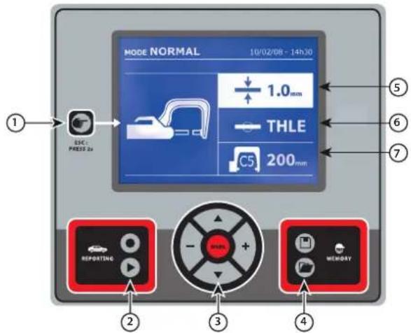
MAN TO MACHINE INTERFACE
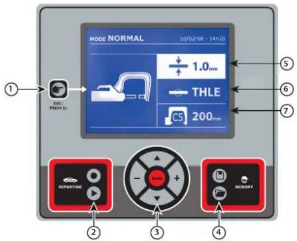
text_image
MODE NORMAL 10/02/08 - 14h30 ① EVE PRESS 2s 1.0 mm THLE C5 200 mm ② REPORTING ③ MEMORY
Button

- Push briefly the button to choose between the modes clamp, gun or «clamp settings».
- Push the button for 2 seconds to return to the «normal» mode from all the other modes.
- Push the button for 2 seconds to reset the spot count when it is on display.
- Push the button for 2 seconds to return to the «Settings» menu.
- Push briefly twice to erase the log displayed in the log view mode.
- Push briefly the button, in the programs saving mode, erase the program selected.

Saving a report
This function is detailed in the corresponding chapter.
Button activates or deactivates the creation of a report. Button is used to view the points completed.

Using the different modes
Button is used to move through the different welding modes. A prolonged push on the mode button activates the settings mode used to select the language, set the date and activate the warning sound for «current too low» or «pressure too low». Buttons (▲r) are used to navigate through and select the value that needs to be adjusted, and then buttons + and - are used to increase or decrease that value.

Saving the settings
- Button is used to save a machine setting (these are the settings that have been adjusted through the manual mode: current, duration and tightening).
- Button is used to re-establish a setting saved previously under the same name. The machine starts automatically in manual mode using the welding settings (current, duration and tightening) and the tool (clamp or gun saved).

Setting the thickness of the plate
The value to be entered is in relation to the thickness of the sheets being welded on. The selection of the thickness is done using the + and - buttons, the different thicknesses available are 0.6, 0.8, 1.0, 1.2, 1.5, 1.8, 2.0, 2.5 and 3.0 mm.

Setting the type of plate
This setting is used to specify the type of metal plate being welded on, the different choices are : coated steel, HLE/THLE steel, UHLE steel and bore/USIBOR steel. This setting can also be adjusted using the + and - buttons.

Setting up the arm
SETTING UP THE G CLAMP

Lock the G arm in place using the lever (FIG 2 - 1).
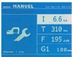
text_image
MODE MANUEL 64/04/15 00:13 I 6.6 kA T 310 ms F 195 dN G1 100mm Position 7.0 StarUse the button in order to select the clamp setting function. The «clamp setting» function is used to close the clamp and to apply the pressure pre-selected at the electrodes without power going through. The clamp remains closed while the trigger is pressed. This function is designed to verify the centering of the end bits.
Push the button 📋 for 2 seconds to return to the AUTO mode.
For the GYSPOT PTI GENIUS, always ensure to be in that mode to stop the pump when changing the arms. The electrode retracts into the clamp. The red indicator on the button (FIG 2 - 12) lights up when the pump stops.
THE DIFFERENT WELDING MODES
For all the models :
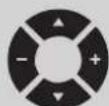
The buttons (▲ or ▼) are used to select the settings that need to be adjusted. Each adjustment is done by pressing the side keys + and -.
The button (FIG 2 -12) on the clamp is used to remotely adjust the welding settings (thickness, type of steel):
- Long push : change of setting (to go from one setting to another)
- Short push : modification of the value
This button does not allow to change the arm on the screen. To change the arm (G1 to G2 for instance), the user must use the machine keypad.
Insufficient network pressure :
If the input pressure is insufficient to provide the correct pressure, the machine shows an error message before the weld «Insufficient network pressure». Pressing the trigger a second time is used to «force» the spot weld using the available pressure.
Low current :
If the current obtained during the spot weld is below the expected value (<6 %), the machine displays «low current» after the weld which means that the weld must be checked.
In any case, a message is displayed at the end of the weld indicating the current and pressure measured. This message remains on display on the screen until the user pushes a button on the keypad or carries on welding (FIG 2 - 11).

The welding conditions must be reviewed at the start of each new job. «Test» weld spots must be carried out on metal panels or sheets similar to the new job being undertaken. Carry our two spot weld with appropriate space in between, in line with the requirement of the job. Test the strength of the second weld. The test is successful if, when pulling the spot out, the panel breaks and the centre is extracted. The centre must have a minimum diameter in line with the specifications of the make of the vehicle.
AUTO mode
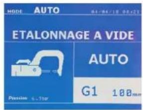
text_image
MODE AUTO 01/04/12 05/12 ETALONNAGE A VIDE AUTO G1 100mm Pascension 4.375pThis mode is displayed by default when the machine starts.
This mode is used to weld sheets/panels without having to specify any settings on the screen. The machine sets the appropriate settings automatically.

text_image
HODE AUTO 04/06/18 06:21 AUTO G1 100mm Pressure 4.30rIn order to use this mode, do a blank spot weld (without any sheet/panel between the electrodes), as prompted on the display. Push the button (FIG 2-11). The message «Do a spot without a load» is displayed on the screen. Push the button again to calibrate. Once the calibration is done, the machine shows all the settings to zero, and is ready to weld. Close the clamp on the area to weld and weld automatically, without entering any parameters in the machine. Every 30 spots, a new calibration will be required.
This mode can be used when using all arms except the G7.
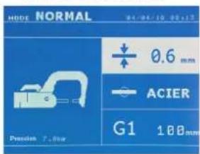
NORMAL mode
text_image
HUBE NORMAL 04-04-10 05-15 0.6 mm ACIER G1 100mm Precision 7.00mmThis mode determines the welding settings based on the thickness of the sheets/panels and the type of steel.
The settings that need to be set when using this mode are:
- Thickness of the sheets/panels, with a range between 0.60 mm and 3.00 mm.
When 2 sheets/panels are being welded together, enter the thickness of the thinnest sheet.
When 3 sheets/panels are welded together, use the total cumulated thickness and divide by 2.
- Type of steel (coated steel, HLE/THLE steel, UHLE steel, bore steel (BORON)).
When welding a mix of different types of steel, select the strongest one.
- Reference of the arm used.
Push the button 2 seconds to return to the AUTO mode.
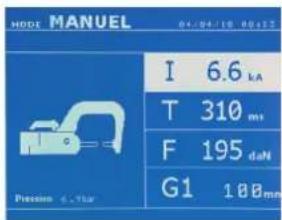
MANUAL mode
text_image
MODE MANUEL 04/04/10 00:12 I 6.6 kA T 310 m/s F 195 dN G1 1.00mm Pleasen 6.75arThis mode is used to select the parameters of the spots by following the instructions of a repair book.
The parameters to set in this mode are:
- Current
- Duration
- Pressure
- Reference of the arm used.
Push the button 2 seconds to return to the AUTO mode.
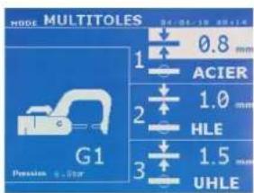
MULTI mode
text_image
MODE MULTITOLES G1 Pressure 6.50mm 0.8 mm ACIER 1.0 mm HLE 1.5 mm UHLEThis mode is used to set precisely the thickness and type of steel for each sheet/panel.
The first element (thickness of sheet 1) is selected. The keys up and down are used to select the setting that needs to be adjusted, where the keys right and left are used to increase or decrease the value. Highlight the setting that needs to be adjusted.
The settings that need to be set when using this mode are:
- Thickness of the sheets/panels, with a range between 0.60 mm and 2.50 mm.
- Type of steel (coated steel, HLE/THLE steel, UHLE steel, bore steel (BORON)).
When welding a mix of different types of steel, select the strongest one. - To activate the sheet/panel 3, press the scroll keys (▲) to highlight sheet/panel 3. Then use they keys + and - to select the thickness of the sheets/panels.
- Reference of the arm used.
Push the button 2 seconds to return to the AUTO mode.
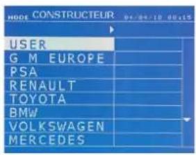
MANUFACTURER mode
text_image
NODE CONSTRUCTEUR G M EUROPE PSA RENAULT TOYOTA BMW VOLKSWAGEN MERCEDESThe MANUFACTURER mode is optional; it can be modified using the « Settings » menu.
This mode is used to name a pre-registered spot based on the repair book issued by the manufacturer.
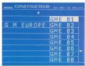
text_image
MODE CONSTRUCTEUR G M EUROPE GME 01 GME 02 GME 03 GME 04 GME 05 GME 06 GME 07 GME 08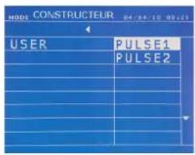
text_image
MODE CONSTRUCTEUR 04/04/10 09:25 USER PULSE1 PULSE2Spot welds programmed by the user can be recalled by selecting USER in the manufacturers list. Welding spots can be programmed using the GYSPOT software and the welding spots settings module.
Push the button

for 2 seconds to return to the AUTO mode.
ENERGY mode
text_image
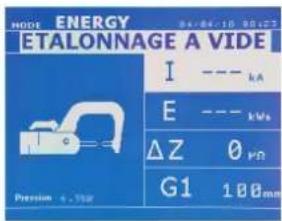
MODE ENERGY ETALONNAGE A VIDE I --- kA E --- kWs ΔZ 0 ΦΩ G1 100mm Precision 4.15arThe ENERGY mode is optional and can be set using the «Settings» menu.
This mode is used to control the energy transmitted during the weld. This mode is not designed to be used during repairs but for the benefit of manufacturers and quality control organisations conducting tests.

To enable this mode, first perform a weld without a load. Push the button (FIG 2 -11). The message «Do a spot without a load» is displayed on the screen. Push the button again to calibrate. Once the calibration has been done, the machine displays the last values used in this mode for current and energy. The use can then modify the welding current, energy and resistance. The duration of the weld will vary based on the time required for the machine to reach the energy level required. If it is taking too long, the machine will display the error message «maximum duration reached».
Push the button

for 2 seconds to return to the AUTO mode.
SETTINGS MENU
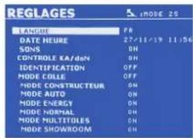
text_image
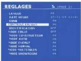
REGLAGES L'ANGUE DATE HEURE SONS CONTROLE KA/daN IDENTIFICATION MODE COLLE MODE CONSTRUCTEUR MODE AUTO MODE ENERGY MODE NORMAL MODE MULTITILES MODE SHOWROOM 27/11/19 11:56 ON OFF ON ON ON ON ON ON ON ON ON ON ON ON ON ON ON ON ON ON ON ON ON ON ON ON ON ON ON ON ON ON ON ON ON ON ON ON ON ON ON ON ON ON ON ON ON ON ON ON ON ON OKThis menu is accessible by pressing and holding the button for 2 seconds.
The language used in the menu can amended on line 1.
The date and the time can be programmed on line 2.
The modes GYSTEEL, MANUFACTURER, AUTO, ENERGY, NORMAL et MULTISHEETS can be activated or deactivated using this menu.
text_image
REGLAGES LANGUE DATE GUIDE SONS CONTROLATION IDENTIFICATION MODE COLLE MODE CONSTRUCTURE MODE AUTO MODE ENERGY MODE NORMAL MODE MULTITIBLES MODE SHOWROOM xMODE 21daN control :
This setting is used to activate or control the clamping force of the clamp during welding.
GLUE mode:
On the SETTINGS screen below, the user can specify the presence glue between the panels/sheets. When this mode is in use, a pre-spot is performed before the weld. The duration of this pre-spot is set in milliseconds, from 0 to 400 ms, with 50 ms thresholds. When the glue mode is selected, la word « GLUE » is displayed in the menus of the NORMAL, MANUAL, MULTI or GYSTEEL welding modes.
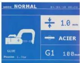
text_image
MODE NORMAL 04-09-10 08:25 + - 1.0 mm ACIER G1 100mm GLUE Precision 6.75ar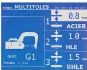
text_image
MODE MULTITOLES 0.4/04-13 0.8 mm ACIER 1.0 mm HLE 1.5 mm UHLE GLUE G1 Pressure 6.15p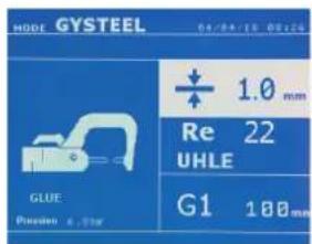
text_image
HODE GYSTEEL 04/04/15 09/26 + 1.0 mm Re 22 UHLE G1 180 mm GLUE Position 4, StarERROR MANAGEMENT
text_image
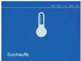
0.4 / 0.4 / 2.5 0.5 + 2.5 SurchauffeVarious elements may produce errors. They can be split into 4 categories :
1/ Warning messages designed to warn the operator of overheating, lack of pressure or power, etc.
These messages are displayed on the screen and remain visible until a button is pressed.
2/ The faults that occur in relation to insufficient air pressure or power supply.
3/ The serious faults that block the machine. In this case, contact the service department
4/ The thermal protection is linked by a thermistance on the diode bridge and when it activates the machine is locked and the message «overheating» is displayed.
Low battery

text_image
04/04/18 08:28 Batterie faibleThe message «Battery low» is displayed when the machine is switched on and it indicates that the battery on the command board is low. This battery is used to record the date and time when the machine is switched off.
Invalid tool

text_image
04/04/25 09:28 Outil non valideThe message «Invalid tool» is displayed when the machine is switched on and indicates that a button is pushed in, the trigger is pushed in or a permanent short-circuit. Check the trigger or the buttons on the clamps to remove the message.
Invalid arm

text_image
Bras non valideThe arm used is not compatible with the welding mode selected.
Current too low

text_image
Courant trop failure1/ Check the weld
If the current obtained during a spot weld is lower than the expected value (6%), the machine displays the warning message «Low current, check the weld».
2/ Check the sheets
If the machine cannot deliver the current required, the error message «Low current, check the sheets» is displayed. The weld does not happen and the fault must be skipped for the weld to happen.
Insufficient air pressure

Pressing the trigger a second time is used to «force» the spot weld using the available pressure. If the tightening recorded is insufficient, the machine displays «Low pressure».
«p low» is also recorded in the active report.
Pump priming
text_image
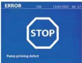
ERROR 128 15/01/2021 09:27 STOP Pump priming defectThe «Pump priming fault» message appears when the cooling system pump is defused. Check the coolant level in the tank.
Self-diagnostic
text_image
CHECK CONFIG 1 PTL 400 AN 2105102470000001 CONTROL: NPY V1.86.83 ALM-RADD: 400V ALM-SOFT: V8.81 RETROGATE CHANNELS: ONION ND 11.01.29-12.2020 U12 = 404V U23 = 403V U35 = 403V U=RT - SETV UPMAPK = 266V UPRPGSET4 = 281V UPRPGSET4 = 281V IGERT = 365V IGERT = 365V IGERT = 66V IGERT = 66V IGERT = 66V PASS PASS PASS PASS PASS PASS PASS PASS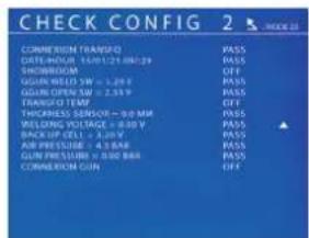
text_image
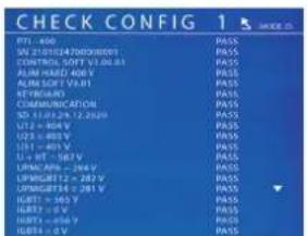
CHECK CONFIG 2 COMMERCEUM TRANSFD OFF/ENGLISH 1540 1278 ON/OFF SHORTROOM GREEN WHEELS 3W = 1.20 V GREEN OPEN S/W = 2.93 P TOLERED TEMP THICKNESS SENSOR = 0.00 MM WEATHER VOLTAGE = 0.00 V BACK-UP CILL = 4.00 V AIR PRESSURE = 4.5 BAR CORN PRESSURE = 0.00 BAR COMMERCEUM CUN PASS PASS OFF PASS PASS PASS PASS OFFWhen the power is turned on, the machine performs self-diagnostics and displays the results on the screen.
If no blocking error is present, this page is displayed for 3s and then disappears. During this period, a short press of the MODE buttons, ▲ or ▼, leaves the CHECK pages displayed (results summarized on two pages). A long press on MODE will exit the CHECK mode.
It is not possible to exit the CHECK pages if a blocking fault is detected, except for a phase failure (see list below).
| Line no. | Comment Display left column | Display right column | Type of defect In the event of a blocking fault | ||
| Page CHECK n°1 | |||||
| 1 Name of the product PTI-400 PASS No blocking | |||||
| 2 Product serial number SN xx.xx.xxxxxx.xxxxxx PASS or FAIL No blocking | |||||
| 3 Secondary soft version | CONTROL SOFT Vxx.xx.xx | PASS No blocking | |||
| 4 Hard primary version ALIM HARD | 400V PASS or FAIL Blocking | Wrong power supply card, contact your dealer. | |||
| 5 Primary soft version | ALIM SOFT Vx.xx | PASS, FAIL | Blocking | Wrong software version, contact your reseller. | |
| 6 Keyboard test | KEYBOARD | PASS or FAIL | No blocking | Make sure that no key on the keypad or trigger is pressed, if the fault persists contact your dealer. | |
| 7 Communication test μ COMMUNICATION PASS or FAIL Blocking | Communication problem between the cards, contact your retailer. | ||||
| 8 SD card | SD xx.xx.xx.xx.xxxx | PASS or FAIL | No blocking | SD card not present. | |
| 9 Voltage phase 1 | U12 = xxx V | PASS or FAIL | Blocking | If there is no phase, pressing MODE for 5s accesses the Setup menu and allows the machine to operate in Showroom mode. | |
| 10 Voltage phase 2 | U23 = xxx V | PASS or FAIL | Blocking | ||
| 11 Voltage phase 3 | U31 = xxx V | PASS or FAIL | Blocking | ||
| 12 CAPA voltage | U+HT = xxx V | PASS or FAIL | Blocking | Problem controlling the power electronics, contact your dealer. | |
| 13 Voltage PM IGBT 1 and 2 | UPMIGBT12 = xxx V | PASS or FAIL | Blocking | ||
| 14 Voltage PM IGBT 3 and 4 | UPMIGBT34 = xxx V | PASS or FAIL | Blocking | ||
| 15 IGBT test result 1 | IGBT1 = xxx V PASS or FAIL Blocking | ||||
| 16 IGBT test result 2 | IGBT2 = xxx V PASS or FAIL Blocking | ||||
| 17 IGBT test result 3 | IGBT3 = xxx V PASS or FAIL Blocking | ||||
| 18 IGBT test result 4 | IGBT4 = xxx V PASS or FAIL Blocking | ||||
| Page CHECK n°2 | |||||
| 1 Name of the product CONNEXION TRANSFO PASS or FAIL Blocking | Check the connection of the power cable from the gripper to the generator. | ||||
| 2 Test result primary detection transfo | DATE/TIME | PASS or FAIL No blocking | |||
| 3 Date and time | SHOW-ROOM | ON or OFF | No blocking | ||
| 4 SHOW-ROOM mode | GGUN WELD SW = x.xx V | PASS No blocking | |||
| 5 Welding trigger, gun trigger and gun temperature test | GGUN OPEN SW = x.xx V | PASS or FAIL | Blocking | Check the connection of the power diode temperature sensor. | |
| 6 Trigger test on diode opening and temperature | TRANSFO TEMP = x.xx V | ON or OFF | Blocking | Overheating of the power transformer. Allow the machine to cool down before starting up again. | |
| 7 Transformer primary temperature | THICKNESS SENSOR = xx.x mm | PASS No blocking | |||
| 8 Position sensor | WELDING VOLTAGE = x.xx V | PASS No blocking | |||
| 9 Welding voltage | BACKUP CELL = x.xx V | PASS or FAIL | No blocking | ||
| 10 Backup battery voltage | AIR PRESSURE = xx.x bar si PASS | PASS or FAIL | Blocking | Air pressure sensor from the HS network, contact your dealer. | |
| Network pressure | |||||
| 11 Clamp pressure | GUN PRESSURE = xx.x bar si PASS | PASS or FAIL | Blocking | Air pressure sensor of the HS gripper, contact your dealer. | |
| Gun presence detection | |||||
| 12 Detection présence pistolet | CONNEXION GUN | ON or OFF | No blocking | ||
SPOT COUNT
text_image
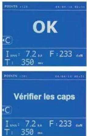
POINTS : 120 04:04:18 00:51 OK C I RNS : 7.2 kA F : 233 daN T : 350 ms POINTS : 120 04:04:18 00:51 Vérifier les caps C I RNS : 7.2 kA F : 233 daN T : 350 msA spot count tool keeps count of the different spot weld done using the same cap. If there is no problem during the welding, the following message is displayed.
The count is displayed at the top left corner of the screen. Press the button 📄 for 2 seconds to reset the count after changing the caps.
The machine counts the number of points achieved with each arm independently. A warning message appears on the screen when the limit of the points made by the headings is reached. The message remains displayed after each point until the counter is reset.

If the caps are not changed after the warning message is displayed and the count is simply reset, they can deteriorate and have a negative impact on the quality of the weld.
RECORDING FEATURES
The Identification mode is optional and can be activated using the «settings» menu.
The log allows to store the parameters of the spots made using the clamp. It is available in all the modes by pressing the 2 buttons and .
The user program is available in all modes by pressing the ☐ and Buttons.
Report (log)
text_image
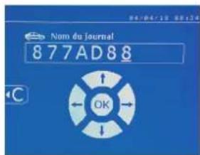
Nom du Journal 877AD88 OKSaving a report allows you to retrieve the data of a series of spot made with using the clamp, and to save them on the memory card so that they can be retrieved from a PC for example. GYS provides a software called GYSPOT to read the SD card and edit the logs on a PC. This GYSPOT software is stored on the SD card as well as the user manual.
By default, this feature is disabled when the machine is switched on. Pressing the recording button (on/off) and the «mode» button starts recording the report in the selected log. Pressing the record button again (on/off) stops the current recording.
The log created contains: an ID entered by the user, as well as for each spot performed, the tool and arm used, the machine settings (power and pressure). It also contains the following possible error messages that may have occurred during its recording: I LOW, P LOW, PB CAPS.
The ID is entered using the 4 keys +, - ▲ or ▼. When entering an identifier already in use, the machine will record the new points in succession, without deleting the previous ones.
The button is used to retrieve a previously saved report and read it back on the screen.
The current recording must be stopped by pressing the ● button before it can be displayed on the screen. The m button is used to exit the report view mode.
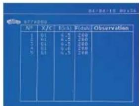
To delete the contents of a report, you must display it on the screen using the button ▶.
Then press the button. The following message appears on the screen.
text_image
47/19/05 AB X/C Cash Flow Observation 1 0.1 4.3 260 2 0.1 4.2 260 3 0.1 4.2 260 4 0.2 4.6 260 5 0.1 4.3 260
text_image
CATALOGUE ©When the triangle is displayed, a second press on the button erases the content of the report displayed.
The triangle disappears from the screen automatically after 3 seconds.
Identification mode
text_image
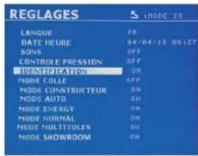
REGLAGES LANGUE DATE HEURE SONS CONTROL EPRESSION TURSDINATION MODE COLLE MODE CONSTRUCTEUR MODE AUTO MODE ENERGY MODE NORMAL MODE MULTITOLER MODE SHOWROOM x MODE 25If the identification mode is set to «ON», all mandatory fields in the repair order must be entered to allow the weld to go ahead or the machine will display «identification fault».
To activate and deactivate the identification mode, an SD identification card must be inserted in the BP card reader instead of the SD card containing the programs.
The settings screen is activated by pressing and holding down the MODE button for 2 seconds.
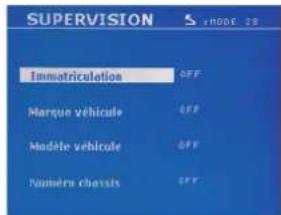
When the SD card «identification» is inserted and «identification ON» is selected, the supervision screen is displayed.
This screen is used to make the fields «registration, vehicle make, vehicle model, vehicle model, chassis number» mandatory fields when entering the repair order.
To exit the screen, press the MODE button for 2 seconds. Then, it is necessary to put the SD card containing the programs back into the machine card reader.
List of screens used to enter a repair order :
If a repair order has already been created, it cannot be changed or deleted on the machine. To delete it, use the Gyspot software on the PC. The user can create a maximum of 100 repair orders.
Repair order User identification Registration (optional)
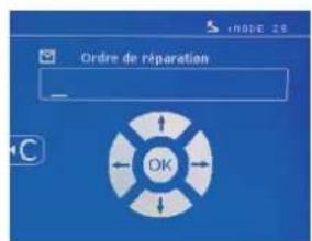
text_image
Immaterculation OKVehicle make Vehicle model Chassis number (optional)
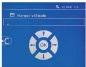
The arrow keys (▲ or ▼) are used to change the letters or numbers. The keys - and + are used to move the cursor inside the field. Press the button briefly to clear the field. The button allows you to scroll through the fields for editing or reading.
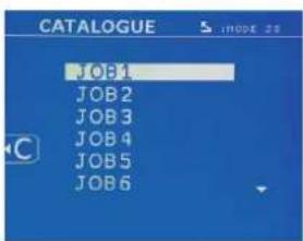
Catalogue
text_image
CATALOGUE : :MODE 25 JOB1 JOB2 JOB3 JOB4 JOB5 JOB6The button is used to consult the repair orders. The page number is displayed (max. 13)
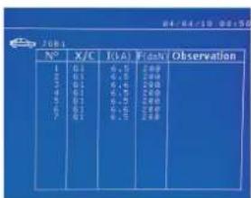
The keys - and + are used to change pages. The keys ▲t an▼used to select previous or next job. The MODE button displays the selected repair order. The button key is used to exit the report view mode.
- The SD card management library allows you to manage your SD cards over 2 GB..
- For each repair order, a log file xxx.dat is associated (with xxx=identifier from 001 to 100). In each log, a maximum of 500 welding points can be
recorded. On consultation, the names of the repair order and the user are displayed.
• The page number is indicated at the top left..
- All repair orders are stored in the file called catalog.GYS.
- This file contains the total number of repair orders, the name of each repair order and the name of each user. There is a maximum of 100 repair orders.
User programs
Saving the settings allows you to define a user program in order to easily find its settings for future use. 20 memory slots are available. Each of them contains the following settings: tool, arm, welding power, welding time and pressure.
A program can be associated to the clamp or gun.
The button is used to save the current settings of the manual mode (power, time and pressure). The 20 memory slots are then indicated by their identifier (for those used) or by a symbol» ---» for free slots..
The ID is entered using the 4 keys stored. When entering an ID that has already been used, the machine will delete the settings that were previously stored.
The button is used to access the settings previously saved. Choosing an empty location has no effect.
Briefly pressing key € deletes the selected program from the list of saved programs.
The key MODE exits the program selection mode, switches the machine to manual mode with the parameters and tool saved in the program.
To deactivate a program, simply change the value of a parameter in one of the three modes manual, normal or multiplate or change the tool (clamp, gun) using the button.
The key allows you to view a previously saved report and read it back on the screen.
SD memory card (ref. 050914)
This card allows the user to link the machine to a PC in order to:
- Retrieve logs (reports), keep a record of the work done, and eventually send it to an insurance company.
- Update welding parameters, add new languages.
- The GYSPOT software for editing parameters on a PC is stored on the SD memory card.
- The instructions are is stored on the SD memory card.
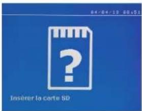
text_image
04-04-13 09:51 Insérer la carte SDThe memory space is sufficient to ensure an autonomy of more than 65,000 points.
The machine can operate without a memory card in «manual» mode only.
If the memory card is not inserted in the card reader, the following message appears. The machine must be stopped and restarted after inserting the SD card.
Important : It is necessary to turn off the power to the machine before removing the SD card from its reader and restart the machine only after inserting the SD card into its reader, otherwise the data saved on the SD card may be lost.
ASSEMBLY AND REPLACEMENT OF THE ARMS ON THE G CLAMP

The warranty does not cover anomalies and damages due to improper assembly of the G-clamp arms.
IMPORTANT :
- do not use copper grease on the arms.
- keep the arm base and arm support on the clamp clean to ensure a good flow of current between the parts in contact.
- If not used for a long time, always store the machine with an arm mounted on the clamp to avoid dust on the arm support.
Procedure for changing the arms :
During the replacement of the arms on the clamp, the cooling circuit pump must be switched off. To do this, place yourself in the «Clamp Setting» mode on the machine; the red light on the clamp button (FIG 2-12) indicates that the pump is off. The electrode retracts into the clamp to allow the arm to be removed.
1 The latch sticks out on the lock side
2 The lever must be in the rear position stop ( 120°)
3 The arrows must be aligned
4 Tilt the arm about 15° and remove it from its housing (the pins must slide into the groove)
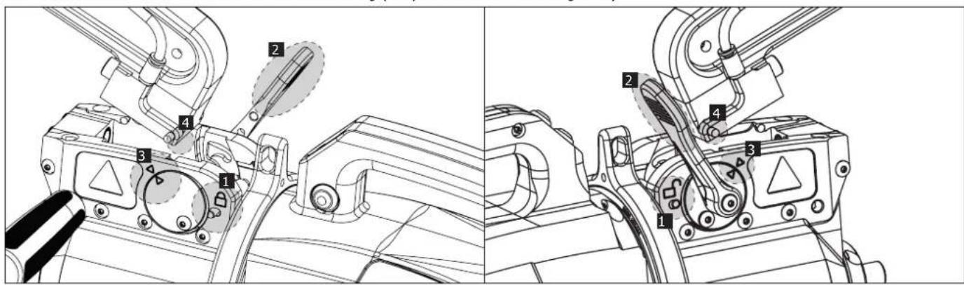
text_image
Technical diagram showing mechanical assembly with numbered components, likely for assembly or maintenance instructions.MECHANICAL OVER-OPENING OF THE ARM
To open the arm and gain easier access to the bodywork, activate the over-opening by pressing the clamp button (FIG 2 -10).
1 Press the button (FIG 2 -10)
2 The latch sticks out on the open lock side
3 The lever must be open ( 90^ ) at the stop on the latch.
4 The arrows must not be aligned
Incline the arm.
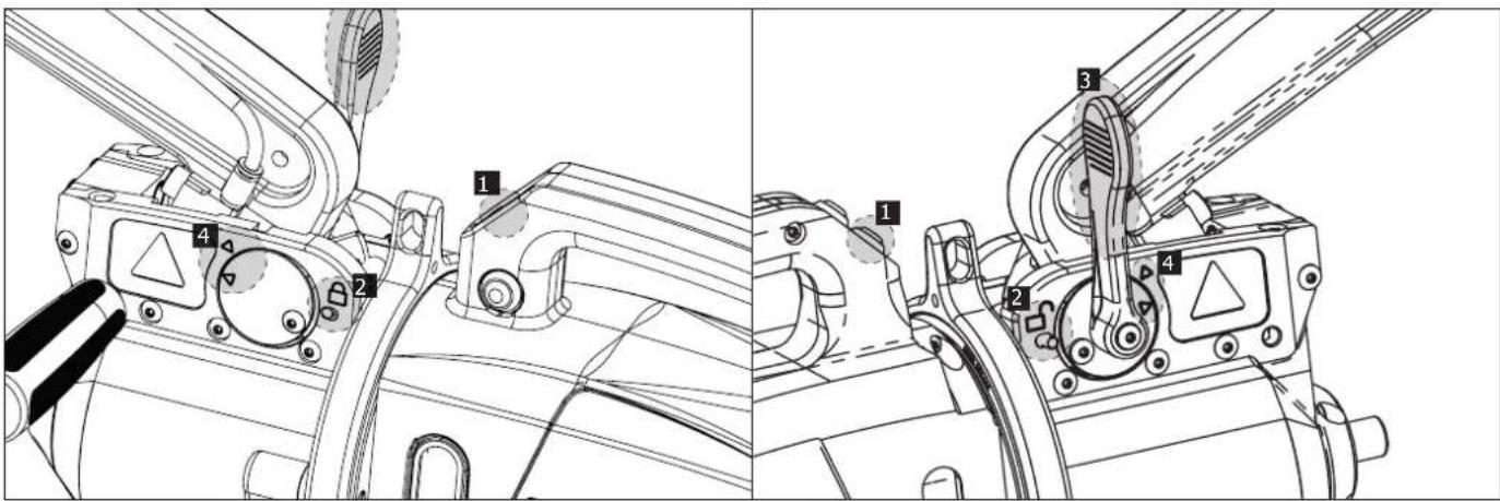
text_image
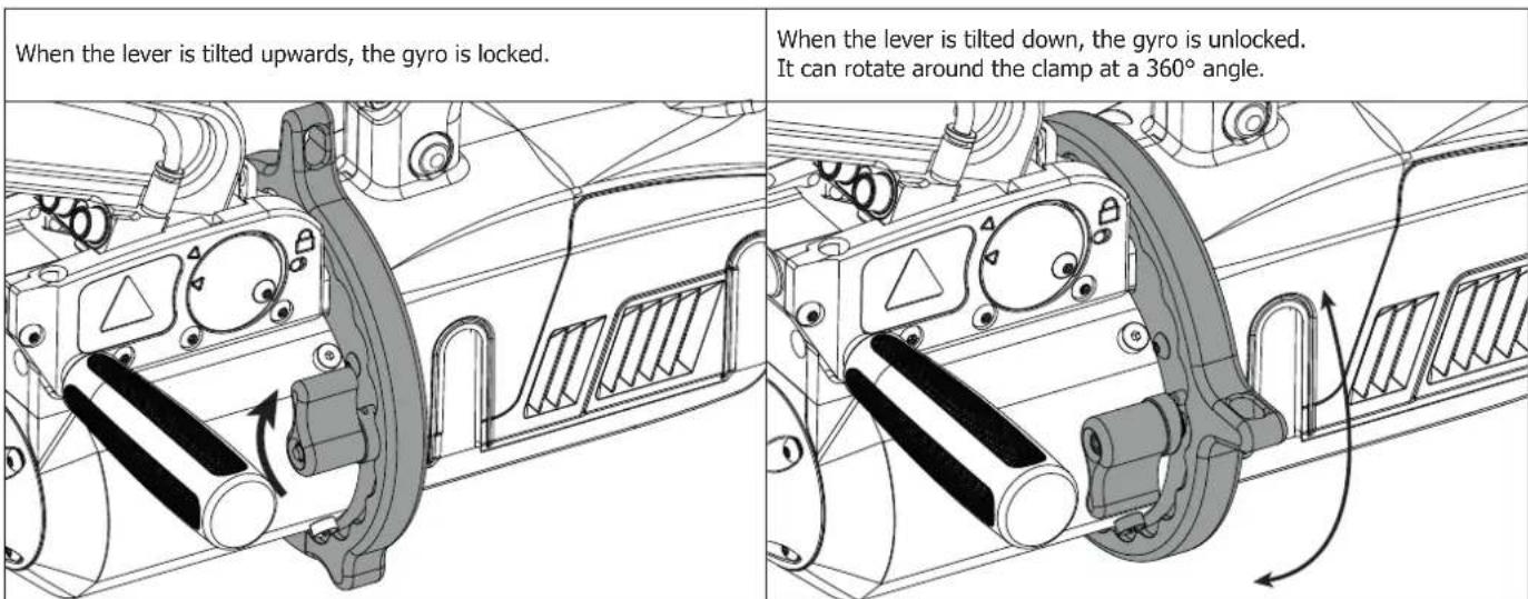
Technical diagram showing mechanical assembly with numbered components and directional arrows indicating movement or force.LOCKING / UNLOCKING OF THE GYROSCOPE
text_image
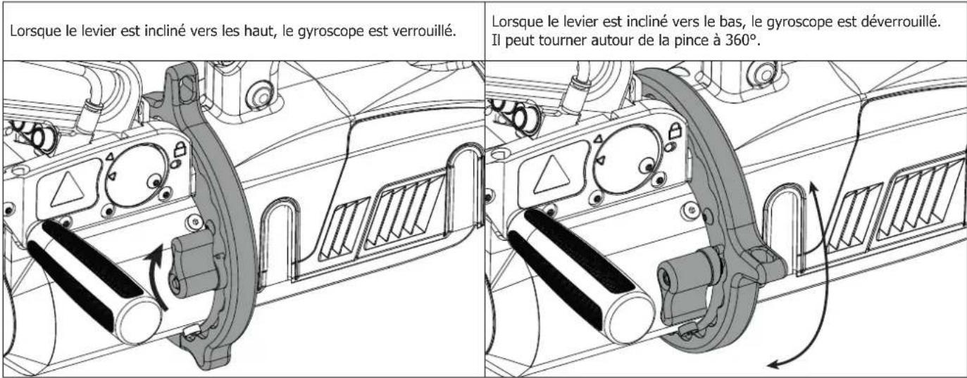
When the lever is tilted upwards, the gyro is locked. When the lever is tilted down, the gyro is unlocked. It can rotate around the clamp at a 360° angle.GYSPOT SOFTWARE ON PC
The purpose of this software is to edit and save the spot weld reports made using a GYSPOT equipped with an SD card reader. To use this software, the PC must be equipped with an SD card reader.
The GYSPOT software can be installed from files on the SD card. In the directory \GYSPOT V X.XX, double click on the file INSTALL.EXE, and follow the instructions to install the software on your PC. A GYSPOT icon is automatically installed on your PC desktop.
1 - Language selection
The software supports several languages. Currently, the available languages are:
French, English, German, Spanish, Dutch, Danish, Finnish, Italian, Swedish, Russian, Turkish.
To select a language, from the menu, click on Options and then on Languages.
Note that once the language has been selected, it is necessary to close and open the GYSPOT software again so that the language can be taken into account.
2 - User identity
In order to personalise the editions with your personal information, some information is required. To give the required information, in the menu, click on Options then on Identity. A new window appears with the following information:
Company name
Address / Post code / City
Telephone / Fax / Email / Website
Logo
The information will then be displayed on the editions.
3 - Traceability
By default, the GYSPOT software opens in «Traceability» mode. In «Point Setting» mode, click on Traceability in the Options menu.
3.1 - Importing point reports from an SD card :
To import the point reports made with a GYSPOT into your PC, insert the SD card into the card reader on your PC and start the GYSPOT software. Then select the reader into which your SD card is inserted and click on the button . When the import is performed, the weld spots performed are grouped by the maintenance order identifier. This identifier corresponds to the name of the report specified in the welding machine. This identifier is displayed in the Current tab.
Once the reports have been imported, it is possible to search, edit or archive each report. To visualise the spot completed in a report, select a report. The spots completed are displayed in the table.
To perform a search, fill in the search field and click on the button

To edit a report, select a report and click on the button

To archive a report, select a report and click on the button 📋. Warning, please note that imported reports cannot be deleted until they have been archived.
3.2 - Consult the archived spot reports:
To view the archived reports, click on the Archives tab. The reports are grouped by year and month.
To view the spots completed, select a report. The spots completed are displayed in the table.
For archived reports, it is possible to search, edit or delete a report.
Be careful, a report archived and then deleted will be imported again when importing data from an SD that has not been cleared.
To perform a search, fill in the search field and click on the button

To edit a report, select a report and click on the button

To delete a report, select a report and click on the button

3.3 - Clearing an SD card:
Clearing the card will erase all completed spot reports recorded on the SD card.
To clear an SD card, insert the SD card into the PC card reader and then, in the menu, click on Options and purge the SD card.
Be careful, when clearing, the spot reports completed that have not yet been imported will be automatically imported.
3.4 - To complete the information in a report:
Each report can be filled in with the following information:
Operator,
Type of vehicle,
Repair order,
Registration,
Date of first registration,
Intervention,
Comments.
To enter this data, select a report and enter the information in the report header.
3.5 - Printing a report :
To print a report, select a report and click on the button

A preview of the edition is displayed. Click on the button

3.6 - Exporting the edition in PDF format:
To export an edition in PDF format, select a folder, then click on the button. A preview of the edition is displayed. Click on the button An example of saving the parameters printed using the GYSPOT software is given below.
4 - Spot parameters
To switch to «Spot Parameter» mode, click on Spot Parameter in the Options menu.
The «Spot parameter» mode allows to use the operator to use spots set by the manufacturers. This mode also allows the user to choose his own welding parameters.
- Insert the SD card supplied with the GYSPOT spot welder into the reader of your PC and select the correct disk in the drop-down menu.
- GYSPOT spot welders support up to 16 files that can contain up to 48 spot settings.
- The first file called «USER» cannot be deleted. It allows the user to add, modify or delete a spot parameter.
- The other files are reserved for the spot set by the manufacturers. It is possible to import manufacturer files downloaded from our website (http://www.gys-welding.com). It is not possible to add, modify or delete a spot parameter taken from a manufacturer file.
4.1 - Import a manufacturer spot parameter file :
| USER | user | |
| GM EUROPE | ||
| PSA | ||
| RENAULT | ||
| TOYOTA |
Double-click in the first column and enter a manufacturer name.
| USER | user | |
| GM EUROPE | ctrl | |
| PSA | ||
| RENAULT | ||
| TOYOTA |
Then double-click in the second column to select a manufacturer file previously downloaded from our website.
| GME 01 |
| GME 02 |
| GME 03 |
| GME 04 |
| GME 05 |
The list of spots set by the manufacturer is displayed in the second list. Select a configured point to view the chronogram and configured parameters.
4.2 - Add a configured spot in the USER file :
| USR001 |
To add a spot to the USER file, select the USER file from the file list and click on the button + to the right of the list of configured spots. Enter the name of the spot and press the TAB key or click outside the list of configured spots to configure the welding parameters.
For a spot to be configured, it is possible to configure:
The pre-tightening stage
The pre-heating stage
The different pulses (4 pulses maximum)
And the hot and cold forging stage.
To change the settings, click on the buttons
When the operator changes a parameter, the spot chronogram is updated.
To validate the spot configuration, click on the button
To cancel the spot configuration, click on the button

4.3 - Modify a spot configured in the USER file:
To change the settings of a spot, select a spot from the list and then change the welding settings.
To validate the changes, click on the button √.
To cancel the changes, click on the button ↻.
4.4 - Delete a configured point in the USER file:
Select a spot parameter from the list and click on the button ✗ to the right of the list.
| YOUR logo | Raisonsociale: | JBDC | Téléphone: | 0243510101 |
| Adresse: | Zl.134BddesLoges | Télécopie: | 0243510102 | |
| Email:contact@companyname.com | ||||
| Codepostal: | 53941 | www.companyname.comSiteWeb: | ||
| Ville: | Saint-Berthevin | |||
| Intervenant: | OPERATEUR | Marque: | PEUGEOT |
| Ordrederéparation: | 977AC92 | Modèle: | 308SW |
| Datedujournal: | 05/04/2018 | N°châssis: | 12355849 |
| Intervention: | AILEARRIERE | Immatriculation: | 1450UT53 |
| Commentaires: | Commentaires | Miseencirculation: | 01/01/2017 |
GYSPOTBP.LG(1712009013)
People operating this machine must receive suitable training in order to get the most out of the machine capabilities and carry out good quality repairs (examples: car body work training).
Preparation of the parts to be assembled
It is essential to clean and accost the area to be welded.
In the case of a protective application, make sure that it is conductive by first testing a sample.
Monopoint electrode welding
When repairing a vehicle, check that the manufacturer allows this type of welding process.
Using the underwing arm
The maximum pressure is 100 daN.
O-rings for the locking nuts of G arm.
Inside the 2 arm locking nuts, there are 2 O-rings that must be replaced in case of a leak or every 6 months. These 2 seals are necessary to avoid any risk of leakage.
These seals are O-rings d=25, group of 4. When replacing these seals, grease must be applied to them. (ref. 050440 : contact grease)
Quantity and quality of the coolant
The coolant level is important for the correct operation of the machine. It must always be between the minimum and maximum level indicated on the trolley. Top up with demineralized water if necessary.
Replace the coolant every 2 years :
| 1 | Switch off the power supply using the switch located at the rear of the machine (OFF position) and disconnect the unit from the mains. | ||
| 2 | Place a bucket (min. 30 l capacity) under the machine drain hole. | ||
| 3 | 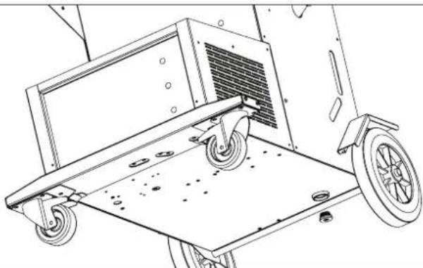 | Unscrew the drain plug located under the machine using a 10 mm torx spanner.(Ref. S6262) | |
| 4 | Rinse the inside of the tank with running water to remove deposits. | ||
| 5 | Replace the drain plug. ( [IMAGE] : 4 N.m) | ||
| 6 | Fill the tank with coolant (5l : 062511 / 10l : 052246) | ||
| 7 | Turn the power back on (ON position) and check for leaks. | ||
TROUBLESHOOTING
| TROUBLESHOOTING CAUSES SOLUTIONS | |||
| Clamp welding | The spot made does not hold or does not enough | The caps are worn out. Change the caps. | |
| The sheets are not clean enough. Check the preparation work. | |||
| The arm selected does not match the one mounted. | Check the arm selected in the software. | ||
| The machine makes a hole in the sheet. | The caps are worn out. Change the caps. | ||
| Insufficient air pressure. Check the air pressure (min. 8 bar) | |||
| The surface is not properly prepared. Prepare/clean the surface to be worked on | |||
| Lack of power | Power supply problem. Check the stability of the mains voltage | ||
| Caps blackened or damaged. Change the caps. | |||
| Incorrect arm locking. | Refer to the chapter "Assembly and changing the arms". | ||
| - Fast overheating of the machine.- Power cable inflation. | No or poor circulation of the coolant. | Open the cart tank cap and observe the movement of the coolant and correct return. | |
| - Pump stopping- Polluted coolant- Circuit blocked. | Obstruction in the cooling circuit (pinched pipe) | Check the sheathing between the trolley.Check that the pump is working properly.Check the condition of the coolant. | |
| Gun | Abnormal heating of the gun | Incorrect tightening of the chuck. | Check the tightness of the chuck, the star holder chuck, and the condition of the sheathing. |
| Gun sheathing loose. | Replace the sheathing in order for the air cooling to reach the inside of the gun | ||
| Incorrect positioning of the earth pad. | Check that the ground pad is in contact with the right sheet metal. | ||
| Lack of power in the gun | Poor contact of the earth pad. Check the earth contact | ||
| Incorrect tightening of the chuck or accessories. | Check the tightness of the chuck and accessories, and the condition of the sheathing | ||
| Damaged consumables. Replace the consumables | |||
WARRANTY
The warranty covers faulty workmanship for 2 years from the date of purchase (parts and labour).
The warranty does not cover:
- Transit damage.
- Normal wear of parts (eg. : cables, clamps, etc..).
- Damages due to misuse (power supply error, dropping of equipment, disassembling).
- Environment related failures (pollution, rust, dust).
In case of failure, return the unit to your distributor together with:
- The proof of purchase (receipt etc ...)
- A description of the fault reported
text_image
A F A F A Anatural_image
Two black fabric clips with a checkmark and an 'X' mark, shown side by side (no text or symbols on the clips themselves)natural_image
Three types of U-shaped metal brackets with mounting holes, shown from different angles (no text or symbols)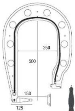
text_image
250 500 180 128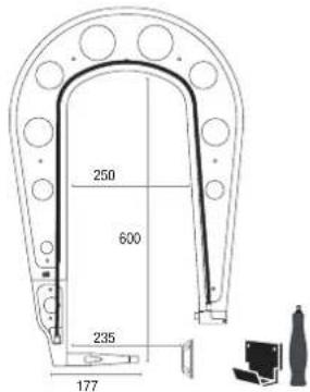
text_image
250 600 235 177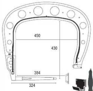
text_image
450 430 384 324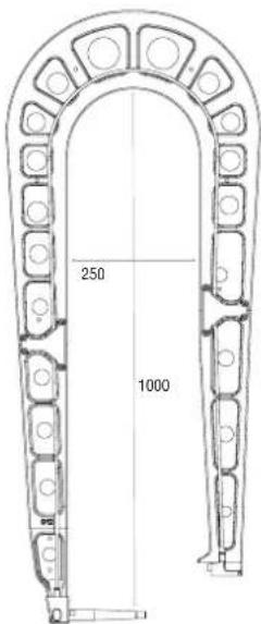
text_image
250 1000
text_image
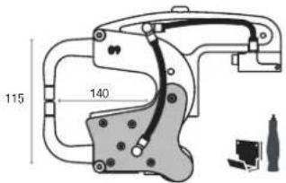
115 140G6 (550 daN) - ref. 022812
G9 + X1 (550 daN) - ref. 022881 - X1 (550 daN) - ref. 050501
G12 (550 daN) - ref. 075238
VERSORGUNG
natural_image
Cross-sectional diagram of a cable showing three labeled wires (L1, L2, L3) without any text or symbols beyond labelsL1 : Phase 1
L2 : Phase 2
L3 : Phase 3
text_image
MODE MANUEL 04/04/10 00:13 I 6.6 kA T 310 ms F 195 dwt G1 100mm Precision 4.5 Startext_image
MODE ENERGY ETALONNAGE A VIDE I --- kA E --- kW ΔZ 0 μΩ G1 100mm Pressure : 5.154text_image
04-04-16 05:28 Surchauffetext_image
ERROR 128 15/01/2021 09:27 STOP Pump priming defecttext_image
Modele vehicle OK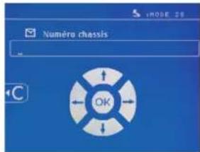
text_image
CATALOGUE JOB1 JOB2 JOB3 JOB4 JOB5 JOB6text_image
Technical diagram showing mechanical assembly with numbered components, likely for assembly or maintenance instructions.ARMBÜGEL-ÖFFNUNG
text_image
Technical diagram showing mechanical assembly with numbered components, likely for assembly or maintenance instructions.text_image
A F A F A Anatural_image
Two black-and-white photos showing a cable buckle being held, with checkmark and cross symbols indicating correct and incorrect states (no text or symbols present)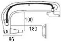 G1 (550 daN) - ref. 022768 INCLUS G1 (550 daN) - ref. 022768 INCLUS | 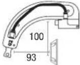 G2 (300 daN) - ref. 022775 G2 (300 daN) - ref. 022775 | 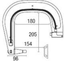 G3 (550 daN) - ref. 022782 G3 (550 daN) - ref. 022782 | 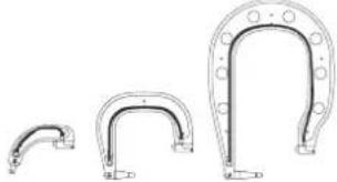 G2 + G3 + G4 - ref. 022898 G2 + G3 + G4 - ref. 022898 | |
 G4 (550 daN) - ref. 022799 G4 (550 daN) - ref. 022799 | 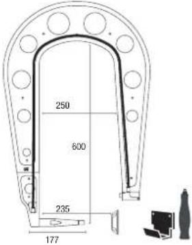 G5 (550 daN) (6.25 kg) - ref. 022805G10 (400 daN) (5 kg) - ref. 067165 G5 (550 daN) (6.25 kg) - ref. 022805G10 (400 daN) (5 kg) - ref. 067165 | 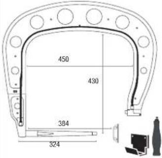 G8 (550 daN) - ref. 022836 G8 (550 daN) - ref. 022836 | 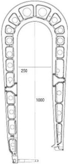 | |
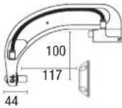 G6 (550 daN) - ref. 022812 G6 (550 daN) - ref. 022812 | 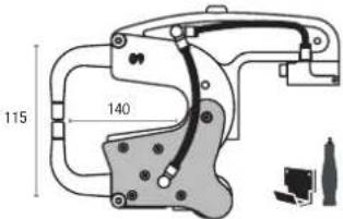 G9 + X1 (550 daN) - ref. 022881 - X1 (550 daN) - ref. 050501 G9 + X1 (550 daN) - ref. 022881 - X1 (550 daN) - ref. 050501 | G12 (550 daN) - ref. 075238 | ||
text_image
NODE ENERGY 04/08-10 90+2 ETALONNAGE A VIDE I --- kA E --- kW ΔZ 0 PΩ G1 100mm Precision 6.75artext_image
04/04/12 05:28 Surchauffetext_image
ERROR 128 15/01/2021 09:27 STOP Pump priming defecttext_image
CHECK CONFIG 1 PTI: 400 PASS SW 2101024700000001 PASS CONTROL: SOUT V1.06.01 PASS ALIM: MARD 400 PASS ALIM: SOUT V3.01 PASS KEYLAND PASS CHINAIRIFICATION PASS SD 51.01.29.12.2020 U12 = 404 V PASS U13 = 403 V PASS U14 = 401 V PASS U = HT = 567 V PASS LPMNCRP = 284 V PASS LPMNGBT12 = 281 V PASS LPMNGBT34 = 281 V PASS IGBT1 = 365 V PASS IGBT2 = 0 V PASS IGBT3 = 656 V PASS IGBT4 = 0 V PASS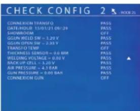
text_image
CHECK CONFIG 2 MODE 25 CORNERION TRANSFQ PRESS DATE: INTEL: 07/01/29 SHOWROOM OFF GREEN WELD SW = 3.20 V PRESS GREEN OPEN SW = 2.33 V PRESS TRANSF TO TEM OFF THICKNESS SENSOR = 0.0 MM PRESS REELDING VOLTAGE = 0.30 V PRESS BACK UP CELLS = 4.0 V PRESS AIR PRESSURE = 4.1 BAR PRESS GUN PRESSURE = 0.00 BAR PRESS CORNERION GUN OFFtext_image
Immatriotulation OKtext_image
Madele vehicle OK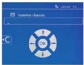
text_image
CATALOGUE JOB1 JOB2 JOB3 JOB4 JOB5 JOB6text_image
Technical diagram showing mechanical assembly with numbered components and labeled partsSOBREAPERTURA MECÁNICA DEL BRAZO
text_image
Technical diagram showing mechanical assembly with numbered components and labeled partsPROGRAMA GYSPOT SOBRE PC
From the After-Sales Service product page : 063419 - G Arm
By clicking on the link : G arms spare parts
By scanning the QR-Code :

text_image
QR code image containing encoded data, no visible human-readable text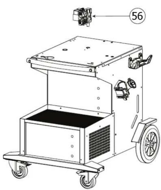
natural_image
Technical line drawing of a mechanical cart with wheels and a numbered component (no text or symbols)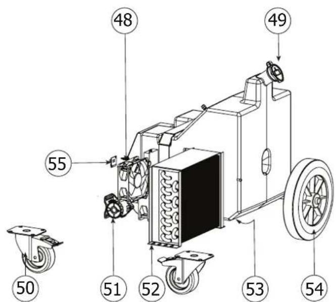
text_image
Technical diagram of a mechanical device with numbered components and labeled parts, including wheels and adjustment knobs.| PTI | ||
| 48 Ventilateur 24 V / Fan 24 V / 24 V Lüfter / Ventilador de 24 V 51021 x 2 | ||
| 49 Bouchon de remplissage ∅40 / Filling plug ∅40 / Einfüllstopfen ∅40 / Tapón de llenado ∅40 71299 | ||
| 50 Roue pivotante / Rotating wheel / Lenkrolle / Rueda giratoria 71362 x 2 | ||
| 51 | Pompe Centrifuge Brushless 10Lit/mn - 24VDC - 80W / Brushless Centrifugal Pump 10Lit/mn - 24VDC - 80W / Bürsten-lose Zentrifugalpumpe 10Lit/mn - 24VDC - 80W / Bomba centrífuga sin escobillas 10Lit/mn - 24VDC - 80W | 71876 |
| 52 | Radiateur à eau 240x225x60 - 1.2Kw/h / Water radiator 240x225x60 - 1.2Kw/h / Wasserheizkörper 240x225x60 - 1,2Kw/h / Radiador de agua 240x225x60 - 1,2Kw/h | 71750 |
| 53 Bouchon de vidange / Drain plug / Ablassschraube / Tapón de drenaje 56262 | ||
| 54 Roue ∅ 250 / Wheel ∅ 250 / Rad ∅ 250 / Rueda ∅ 250 71376 x 2 | ||
| 55 | Circuit Connexion ventilateurs / Circuit Fans connection / Stromkreis Ventilatoranschluss / Circuito Conexión de los venti-ladores | E0058C |
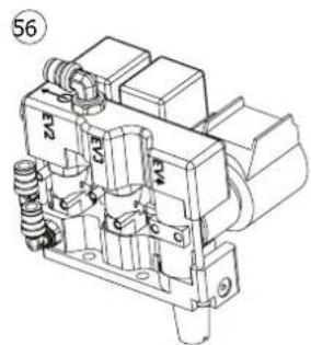
| 56 | Bloc électrovanne / Solenoid valve assembly / Magnetventil-Block / Bloque electroválvula | S81118 | ||
| Electrovannes / Solenoid valves / Magnetventile / Elec-troválvulas : | A | EV2 71797 | ||
| B | EV3 71824 | |||
| C | EV4 71741 | |||
natural_image
Technical line drawing of a mechanical component with no visible text or symbols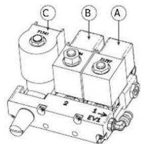
text_image
C B A 2 1→ EV1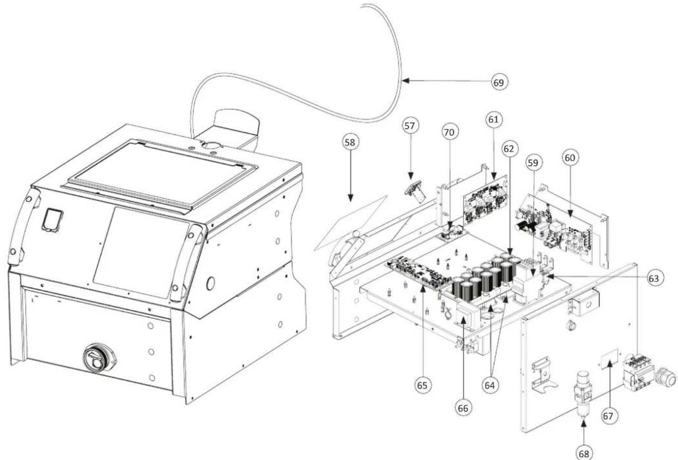
text_image
Technical diagram of an electronic device with numbered components, likely a control panel or industrial machine.| PTI | ||
| 57 | Circuit carte SD / SD card circuit / SD-Karten-Schaltung / Circuito de la tarjeta SD 97028C | |
| Nappe 10pts 40cm / Tablecloth 10pts 40cm / Tischtuch 10pts 40cm / Mantel 10pts 40cm 53095 | ||
| 58 | Clavier / Keyboard / Tastatur / Teclado 51968 | |
| Afficheur LCD / LCD display / LCD-Anzeige / Pantalla LCD 51905 | ||
| 59 | Contacteur de puissance / Power contactor / Leistungsschütz / Contactor de potencia 51131 | |
| 60 | Circuit d'alimentation PTI-G 400 / Power supply circuit PTI-G 400 / Stromversorgungsschaltung PTI-G 400 / Circuito de alimentación PTI-G 400 | E0007C |
| Fusible temporisé 2A / Time-delay fuse 2A / Zeitträge Sicherung 2A / Fusible temporizado 2A 51367 x 3 | ||
| Nappe 10pts 25cm / Tablecloth 10pts 25cm / Tischtuch 10pts 25cm / Mantel 10pts 25cm 53100 | ||
| 61 | Circuit driver PTI-G / PTI-G driver circuit / PTI-G-Treiberschaltung / Circuito conductor PTI-G E0005C | |
| Nappe 10pts 20cm / Tablecloth 10pts 20cm / Tischtuch 10pts 20cm / Mantel 10pts 20cm 53092 | ||
| 62 | Circuit condensateur PTI-G 400 / Capacitor circuit PTI-G 400 / Kondensatorschaltung PTI-G 400 / Circuito de condensa-dores PTI-G 400 | E0003C |
| Fusible 1,6A / Fuse 1.6A / Sicherung 1,6A / Fusible 1,6A 51368 | ||
| 63 | Pont de diode triphasé / Three-phase diode bridge / Dreiphasige Diodenbrücke / Puente de diodos trifásico 52194 | |
| 64 | Module IGBT / IGBT module / IGBT-Modul / Módulo IGBT 52200 x 2 | |
| 65 | Circuit commande PTI-G 400 / Control circuit PTI-G 400 / Steuerkreis PTI-G 400 / Circuito de control PTI-G 400 E0276C | |
| 66 | Transformateur de courant / Current transformer / Stromwandler / Transformador de corriente 96019 | |
| 67 | Interrupteur différentiel 25A 30mA / Differential switch 25A 30mA / Differenzialschalter 25A 30mA / Interruptor diferen-cial 25A 30mA | 52344 |
| 68 | Filtre régulateur air / Air regulator filter / Luftregulierungsfilter / Filtro regulador de aire | 71729 |
| 69 | Cordon d'alimentation / Power supply cable / Netzleitung / Cable de alimentación / Кабель массы / Voedingskabel / Cavo d'alimentazione | F0080SE |
| 70 | Circuit commande à distance potence / Remote stem control circuit / Fernsteuerungsschaltung des Vorbaus / Circuito de control remoto para el vástago / Схема дистанционного управления штоком / Afstandsbedieningscircuit voor de stuurpen / Circuito di controllo remoto per lo stelo | E0119C |
SCHÉMAS ÉLECTRIQUE / CIRCUIT DIAGRAM / SCHALTPLÄNE / ESQUEMAS ELÉCTRICOS
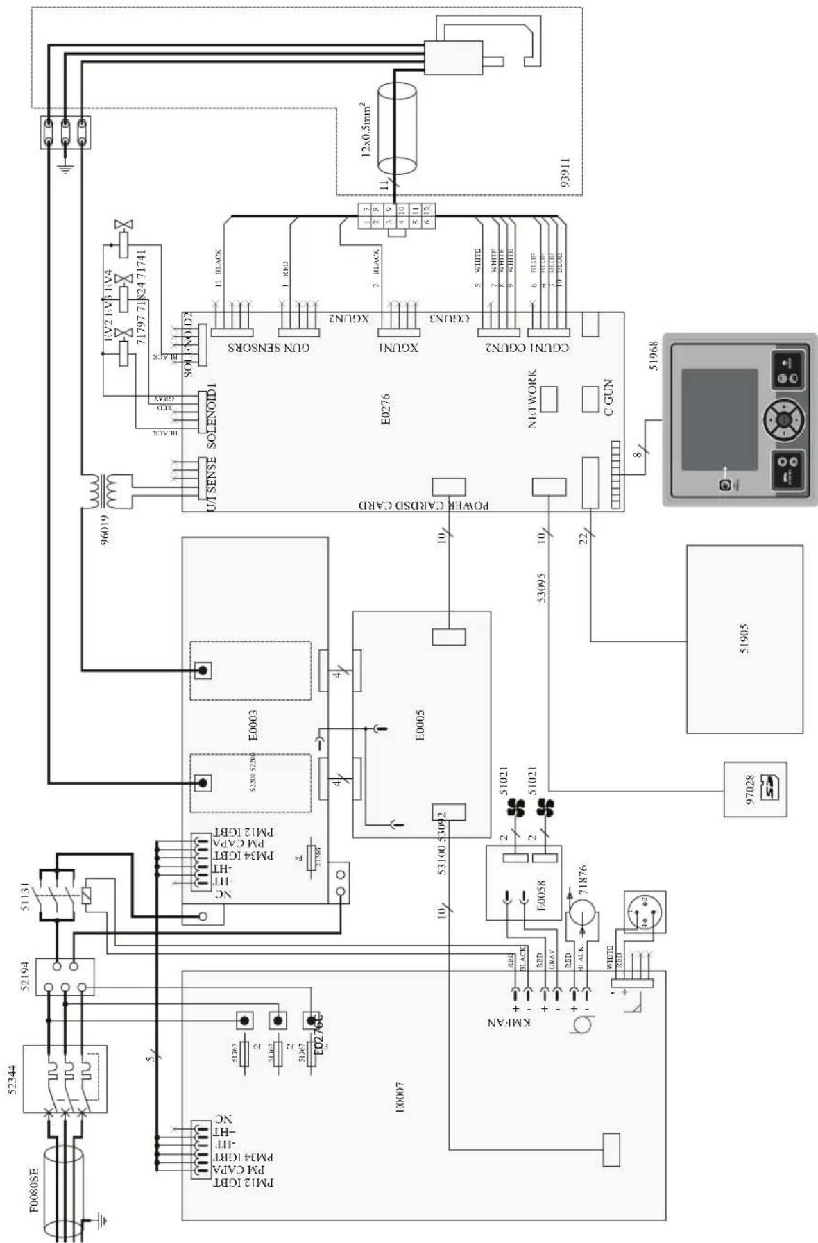
text_image
Electrical schematic diagram of an electrical circuit with labeled components and wiring connectionsSCHÉMA FAISCEAUX / CABLE ASSEMBLY SCHEMATICS / SCHLAUCHPAKET SCHALTPLAN / ESQUEMA CABLEADO
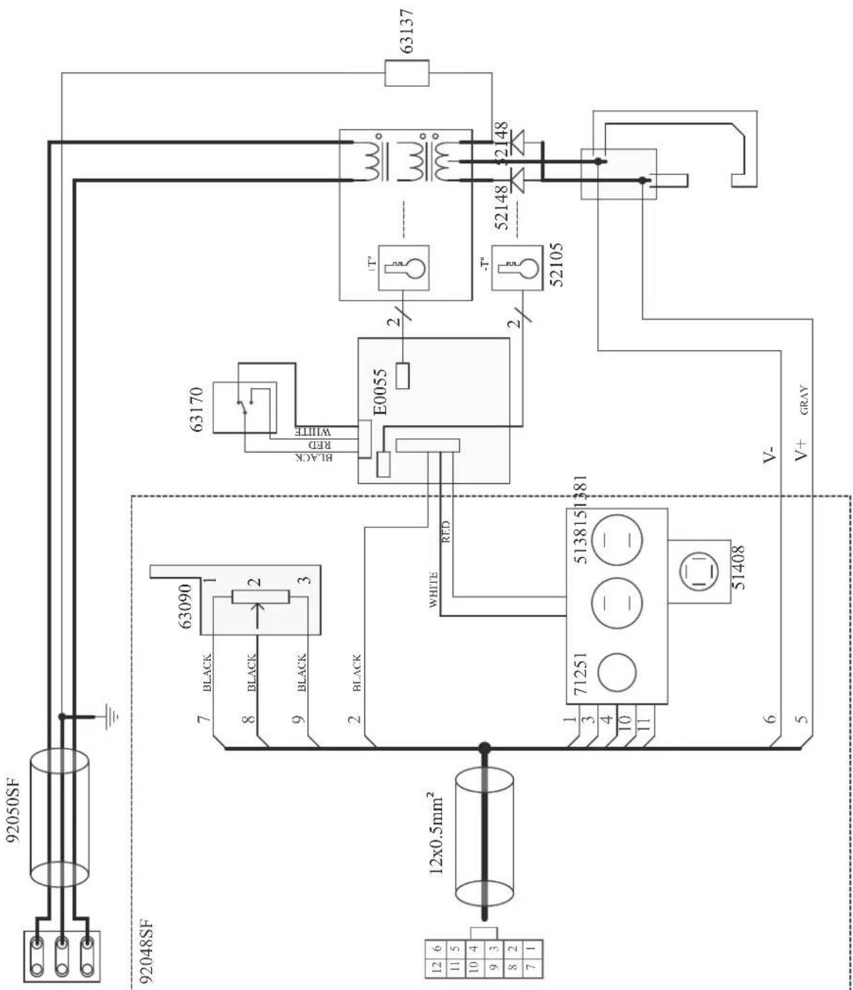
text_image
92050SF 92048SF 12x0.5mm² 12 6 11 5 10 4 9 3 8 2 7 1 63090 7 BLACK 8 BLACK 9 BLACK 2 BLACK 63170 BLACK RED WHITE E0055 WHITE RED 1 3 4 10 11 71251 5138151381 51408 6 V- V+ GRAY 63137 -T° 52148 52148 52105SCHÉMA PNEUMATIQUE / PNEUMATIC SCHEMATICS / PNEUMATISCHER SCHALTPLAN / ESQUEMA NEUMÁTICO
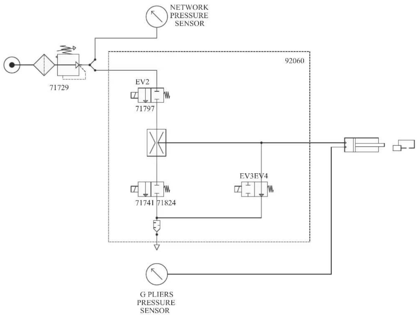
flowchart
graph TD
    A["Network Pressure Sensor"] --> B["71729"]
    B --> C["71797"]
    C --> D["71741 71824"]
    D --> E["EV3 EV4"]
    E --> F["Network Pressure Sensor"]
    G["G PLIERS PRESSURE SENSOR"] --> H["92060"]
    style A fill:#f9f,stroke:#333
    style B fill:#ccf,stroke:#333
    style C fill:#cfc,stroke:#333
    style D fill:#fcc,stroke:#333
    style E fill:#cff,stroke:#333
    style F fill:#ffc,stroke:#333
    style G fill:#fcc,stroke:#333
SCHÉMA HYDRAULIQUE / HYDRAULIC SCHEMATICS / HYDRAULISCHER SCHALTPLAN / ESQUEMA HIDRÁULICO
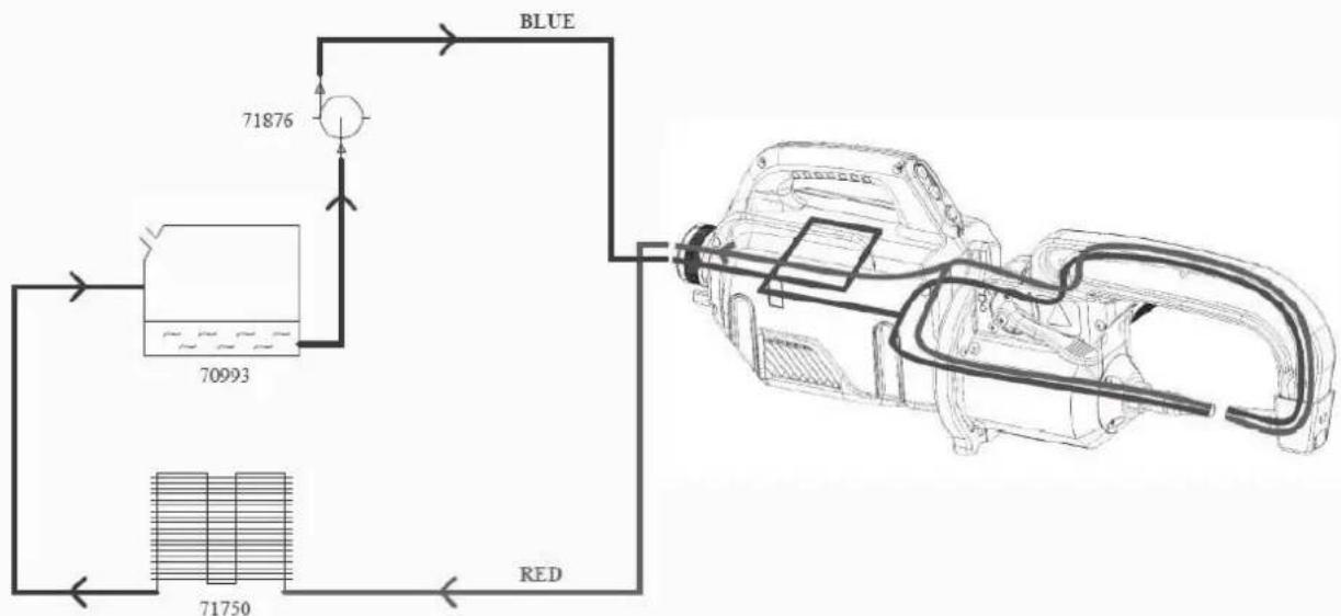
flowchart
graph TD
    A["Device 70993"] --> B["Blue Signal"]
    A --> C["Red Signal"]
    B --> D["Output"]
    C --> E["Output"]