
GearMe - Pump DANFOSS - Free user manual and instructions
Find the device manual for free GearMe DANFOSS in PDF.

| Product type | Hydraulic gear pump |
| Brand | Danfoss |
| Model | GearMe (Aluminum Group 2 Flex Pump) |
| Displacement | 3.9 to 25.2 cm³/rev (depending on variant) |
| Nominal pressure | Up to 250 bar (depending on displacement) |
| Peak pressure | Up to 280 bar |
| Minimum speed | 500 to 1400 rpm (depending on pressure) |
| Maximum speed | 3000 to 4000 rpm |
| Weight | 2.3 to 3.3 kg (depending on displacement) |
| Moment of inertia | 21.3×10⁻⁶ to 74.1×10⁻⁶ kg·m² |
| Body material | Aluminum |
| Mounting type | Flanges E10, B10, B20, B22, SA1, SA2, SB1 |
| Shaft type | Several options (T50, T80, PS1, PS3, S09, S11, S13, SD1, SD2, N11) |
| Inlet/outlet ports | Threaded or flanged (multiple dimensions) |
| Shaft seal | VITON (option) |
| Sealing | NBR (standard) |
| Fluid temperature | -20°C to 100°C (estimate depending on seal) |
| Recommended viscosity | 20 to 100 cSt (estimate) |
| Main functions | Hydraulic power supply for mobile and industrial systems |
| Maintenance | Check seals, clean surfaces, periodic oil change |
| Safety | Respect nominal pressures, do not exceed max speed, use compatible fluids |
| Spare parts | Adaptation kit (code 11268956) for multiple pumps, seals, shafts, flanges |
| Dimensions | Vary according to displacement and flange (e.g., length A: 50.5 to 86 mm) |
Frequently Asked Questions - GearMe DANFOSS
User questions about GearMe DANFOSS
0 question about this device. Answer the ones you know or ask your own.
Ask a new question about this device
Download the instructions for your Pump in PDF format for free! Find your manual GearMe - DANFOSS and take your electronic device back in hand. On this page are published all the documents necessary for the use of your device. GearMe by DANFOSS.
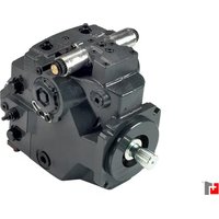
USER MANUAL GearMe DANFOSS
Aluminum Group 2 Flex Pump
Revision history Table of revisions
| Date Changed Rev | |
| June 2023 Added marking position model code option 0207 | |
| February 2023 Fixed typo 0206 | |
| January 2023 Renamed product 0205 | |
| July 2022 QR code on page 5 corrected 0204 | |
| June 2022 Updated pump model code information (special features) 0203 | |
| March 2022 Small updates 0202 | |
| January 2022 Changed cover image, Edited flanges specs and product code information 0201 | |
| April 2021 Corrected PS1 Schematic 0102 | |
| March 2021 First edition 0101 |
Contents
General Information
Overview 4
Pump displacements. 4
Training videos. 5
Technical Information
Technical data. 6
Product Code
Pump model code - Modules. 7
A Family 7
B Displacement 7
C Rotation. 7
D Mounting flange. 7
E Drive Shaft. 8
F Inlet size; G Outlet size. 8
I Rear cover. 8
L Shaft seal. 9
M Sealing. 9
N Screws. 9
O Valve settings. 9
P Marking type 9
Q marking position 9
R Special features. 9
Mounting flange options
Flanges 10
E10. 10
B10. 11
B20. 11
B22. 12
SA1. 12
SA2 13
SB1 13
Shaft options
Shafts. 14
Adapter kit
Dimensions
General Information
Overview
The Flex Program is a flexible solution which gives distributors the possibility to assemble different modules and components according to end-customer specific requirements.
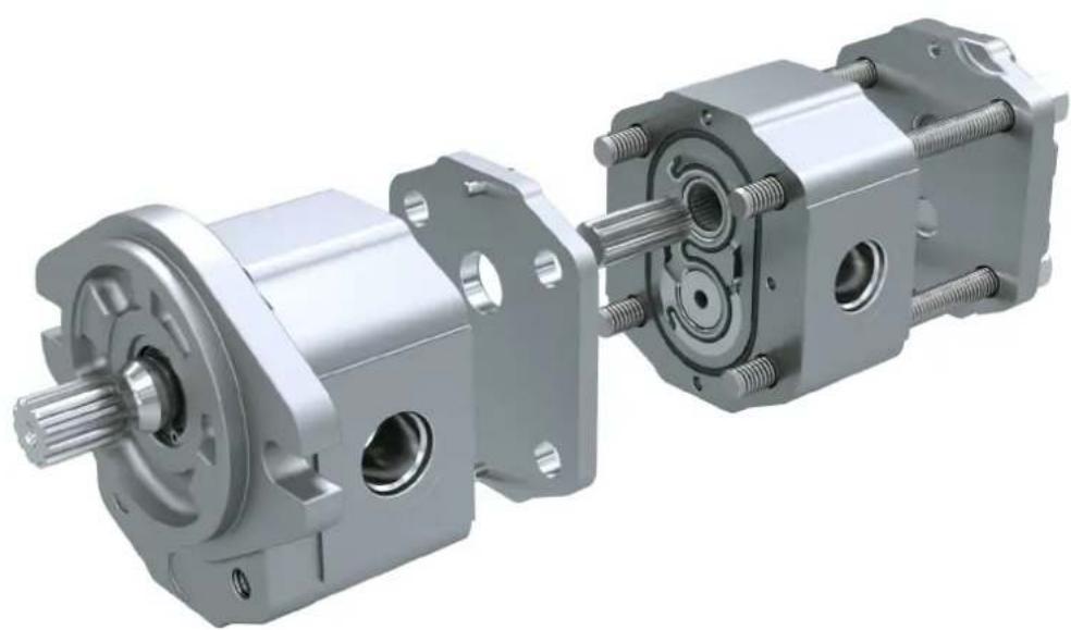
Single pump
Multiple pump
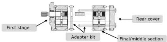
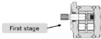
The basic layout is designed to have:
Pre-assembled first sections from factory (submitted to cut-in and tested) then equipped with special shaft with rear spline.
Mid "sections" provided without flange and cover (submitted to cut-in and tested)
- Components (intermediate flanges with coupling, rear covers, assembly screws) supplied individually
Pump displacements
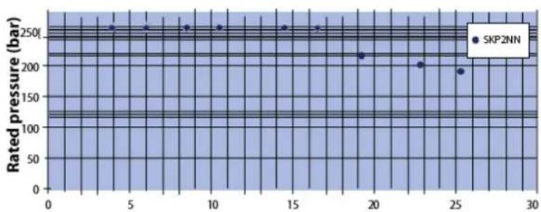
Quick reference chart for pump displacements vs rated pressure
General Information
Training videos
Training videos are accessible at this link: Gear Pumps and Motors - YouTube

Technical Information
Technical data
| Frame size 4.0 6.0 8.0 011 01 | 4 017 019 | 022 025 | |||||||||
| Displacement | cm3/rev[in3/ rev] | 3.9[0.24] | 6.0[0.37] | 8.4[0.51] | 10.8[0.66] | 14.4[0.88] | 16.8[1.02] | 19.2[1.17] | 22.8[1.39] | 25.2[1.54] | |
| SKP2 | |||||||||||
| Peak pressure | bar [psi] 2 | 80[4060] | 280[4060] | 280[4060] | 280[4060] | 280[4060] | 280[4060] | 260[3770] | 230[3335] | 200[2900] | |
| Rated pressure | 250[3625] | 250[3625] | 250[3625] | 250[3625] | 250[3625] | 250[3625] | 240[3480] | 210[3045] | 190[2755] | ||
| Minimum speedat 0-100 bar | min-1(rpm) | 600 600 | 600 500 500 | 500 500 500 | 500 500 | ||||||
| Minimum speedat 100-180 bar | 1200 1200 | 1000 800 | 750 750 | 700 700 | 700 | ||||||
| Min. speed at180 bar to ratedpressure | 1400 1400 | 1400 1200 | 1000 1000 | 1000 1000 | 800 800 | ||||||
| Maximum speed | 4000 4000 | 4000 4000 | 3000 3500 | 3000 3000 | 3000 3000 | ||||||
| Both | |||||||||||
| Weight | kg [lb] 2.3 | [5.1] 2.4 | [5.3] 2.5 | [5.5] 2.7 | [5.8] | [6.3] 3.0 | [6.5] 3.1 | [6.7] 3.2 | [7.0] 3.3 | [7.3] | |
| Moment of inertia ofrotatingcomponents | x 10-6kg·m2[x10-6lb·ft2] | 21.3[505] | 26.5[629] | 32.4[769] | 38.4[911] | 47.3[1122] | 53.3[1265] | 59.2[1405] | 68.1[1616] | 74.1[1758] | |
| Theoretical flowat maximumspeed | l/min[US gal/min] | 15.6[4.1] | 24.0[6.3] | 33.6[8.9] | 43.2[11.4] | 50.4[13.3] | 50.4[13.3] | 57.6[15.2] | 68.4[18.0] | 75.6[20.0] | |
[ 1\mathrm{kg} \cdot \mathrm{m}^2 = 23.68\mathrm{lb} \cdot \mathrm{ft}^2 ]
Caution
The rated and peak pressure mentioned are for pumps with flanged ports only. When threaded ports are required a de-rated performance has to be considered. To verify the compliance of a high pressure application with a threaded ports pump apply to a Danfoss representative.
Product Code
Pump model code - Modules
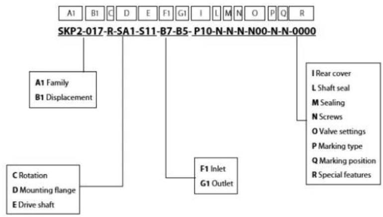
A Family
| SKP2 | High Torque Group 2 Pump |
B Displacement
| 4.0 | \( {3.9}{\mathrm{\;{cm}}}^{3}/\mathrm{{rev}}\left\lbrack {{0.240}{\mathrm{{in}}}^{3}/\mathrm{{rev}}}\right\rbrack \) |
| 6.0 | \( {6.0}{\mathrm{\;{cm}}}^{3}/\mathrm{{rev}}\left\lbrack {{0.360}{\mathrm{{in}}}^{3}/\mathrm{{rev}}}\right\rbrack \) |
| 8.0 | \( {8.4}{\mathrm{\;{cm}}}^{3}/\mathrm{{rev}}\left\lbrack {{0.513}{\mathrm{{in}}}^{3}/\mathrm{{rev}}}\right\rbrack \) |
| 011 | \( {10.8}{\mathrm{\;{cm}}}^{3}/\mathrm{{rev}}\left\lbrack {{0.659}{\mathrm{{in}}}^{3}/\mathrm{{rev}}}\right\rbrack \) |
| 014 | \( {14.4}{\mathrm{\;{cm}}}^{3}/\mathrm{{rev}}\left\lbrack {{0.879}{\mathrm{{in}}}^{3}/\mathrm{{rev}}}\right\rbrack \) |
| 017 | \( {16.8}{\mathrm{\;{cm}}}^{3}/\mathrm{{rev}}\left\lbrack {{1.025}{\mathrm{{in}}}^{3}/\mathrm{{rev}}}\right\rbrack \) |
| 019 | \( {19.2}{\mathrm{\;{cm}}}^{3}/\mathrm{{rev}}\left\lbrack {{1.171}{\mathrm{{in}}}^{3}/\mathrm{{rev}}}\right\rbrack \) |
| 022 | \( {22.8}{\mathrm{\;{cm}}}^{3}/\mathrm{{rev}}\left\lbrack {{1.391}{\mathrm{{in}}}^{3}/\mathrm{{rev}}}\right\rbrack \) |
| 025 | \( {25.2}{\mathrm{\;{cm}}}^{3}/\mathrm{{rev}}\left\lbrack {{1.538}{\mathrm{{in}}}^{3}/\mathrm{{rev}}}\right\rbrack \) |
Other frame sizes and displacements are available upon request.
C Rotation
| R | Right (Clockwise) |
| L | Left (Counterclockwise) |
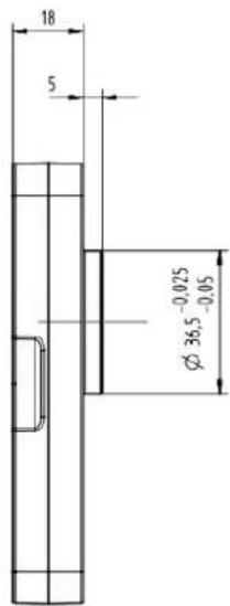
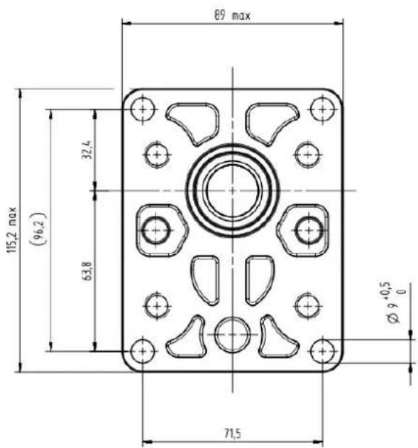
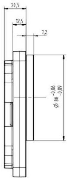
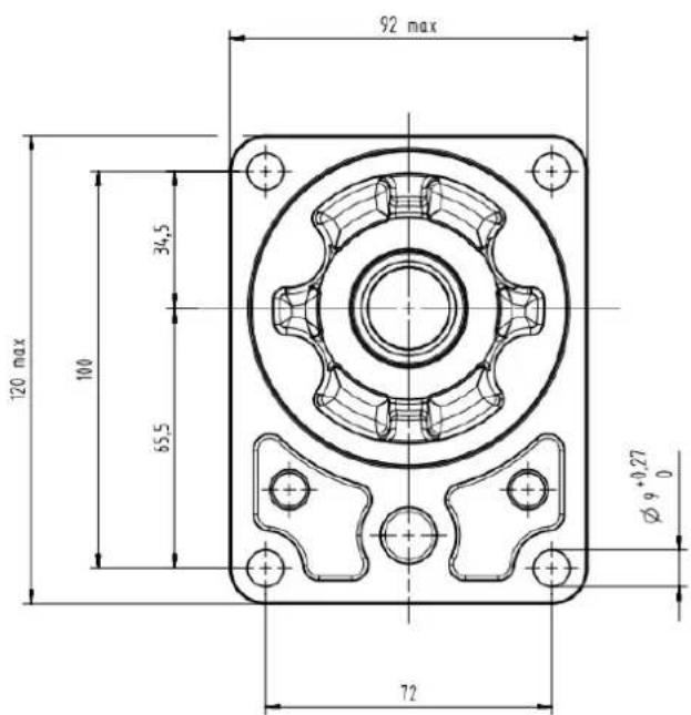
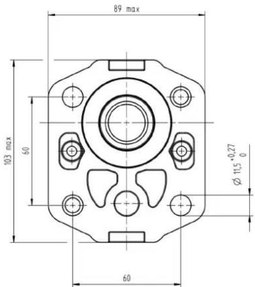
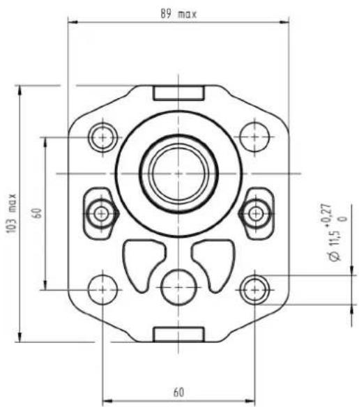
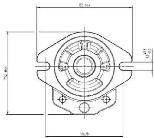
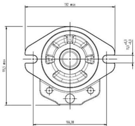
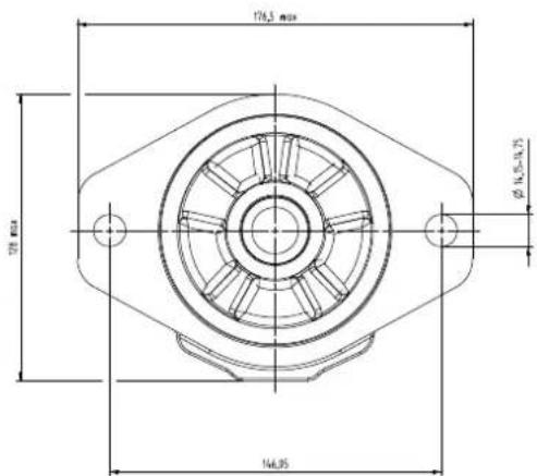
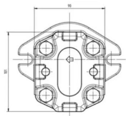
D Mounting flange
| NNN | Without flange |
| E10 | European flange pilot Ø36,5+4 holes |
| B10 | German 4 bolts pilot Ø80 |
| B20 | German 2-bolt ( \ pattern through body) pilot Ø50 |
Product Code
| B22 | German 2-bolt (/ pattern through body) pilot Ø50 |
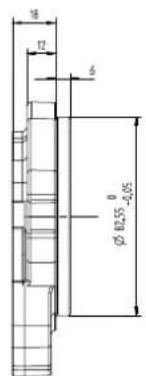
| SA1 | SAE A pilot Ø82,55+2 holes |
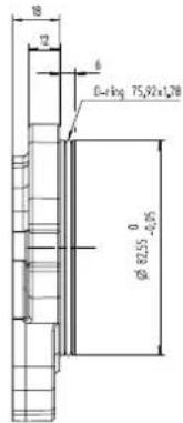
| SA2 | SAE A pilot Ø82,55+2 holes+seal on pilot |
| SB1 | SAE B-pilot Ø101,6+2 holes (available only with drive shaft S13) |
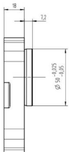
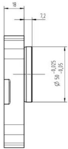
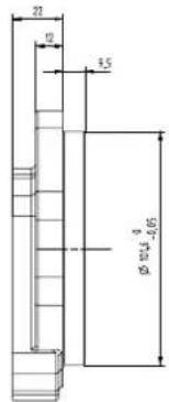
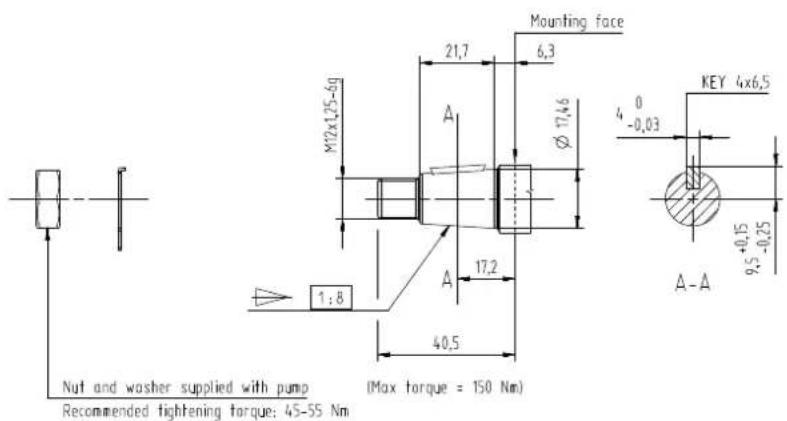
E Drive Shaft
| T50 | Taper 1:5-M12x1,25-Key 3 |
| T80 | Taper 1:8-M12x1,25-Key 4 |
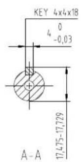
| PS1 | Parallel SAE Ø15,875 (Ø5/8") - L23,8 - Key 4x18 |
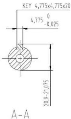
| PS3 | Parallel SAE Ø19,05 (Ø3/4") - L23,8 - Key 4,775x20 |
| S09 | Spline SAE J498-9T-16/32 |
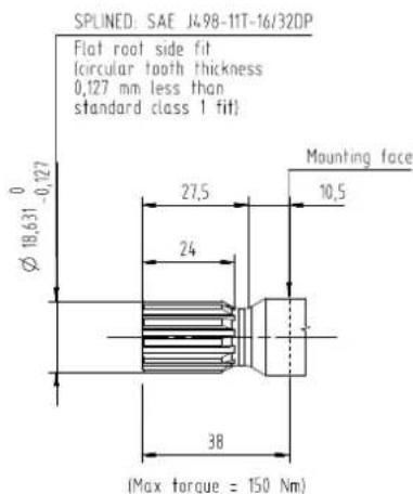
| S11 | Spline SAE J498-11T-16/32 |
| S13 | Splined SAE J498-13T-16/32 (available only with mounting flange SB1) |
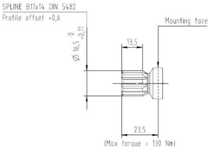
| SD1 | Spline DIN 5482 B17x14 - L10 |
| SD2 | Spline DIN 5482 B17x14 - L14 |
| N11 | No shaft end - internal spline two sides |
F Inlet size; G Outlet size
| B5 | 15x35xM6 | |
| B6 | 15x40xM6 | |
| B7 | 20x40xM6 | |
| C3 | 13,5x30xM6 | |
| C5 | 13,5x40xM8 | |
| C7 | 20x40xM8 | |
| D5 | M18x1,5 | |
| D7 | M22x1,5 | |
| E4 | 3/4-16UNF | |
| E5 | 7/8-14UNF | |
| E6 | 1-1/16-12UN | |
| F3 | 3/8 GAS | |
| F4 | 1/2 GAS | |
| F5 | 3/4 GAS | |
| NN | Without port on body |
For ports combination refer to aluminum gear pumps group 2 catalog, document #BC315962412551
I Rear cover
| NNN | Without cover |
| P10 | Standard pump cover |
| I10 | Cover with relief valve |
Product Code
L Shaft seal
| V | VITON |
M Sealing
| N | NBR |
N Screws
| B | Anti-corrosion screws |
| N | Burnished screws |
| 0 | Without screws |
O Valve settings
| N00 | No valve |
| V** | Integral relief valve |
For valve settings refer to aluminum gear pumps group 2 catalog.
P Marking type
| N | Standard Danfoss Marking |
| A | Standard Danfoss Marking+Customer Code |
| Z | Without Marking |
Q marking position
| $ | Sticker on the body |
R Special features
| 0000 | No special features |
| IS00 | Drive shaft with internal spline at the end, which can also be used as a first stage of a multiple pump |
| BPC0 | Body for ports on cover |
| BSIO | Body for single inlet |
| B017 | Short bearings |
| X001 | IS00+BSIO |
| X002 | IS00+B017 |
| X003 | X001+B017 |
Special features are available upon request. Refer to "Training videos" chapter for more information about special features.
Mounting flange options
Flanges
E10
Mounting flange options
B10
B20
Mounting flange options
B22
SA1
Mounting flange options
SA2
SB1
Shaft options

Shafts
T50
T80
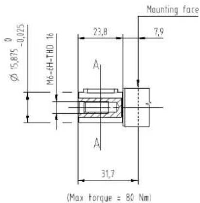
PS1
Shaft options
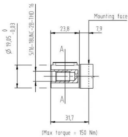
PS3
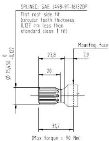
S09
S11
Shaft options
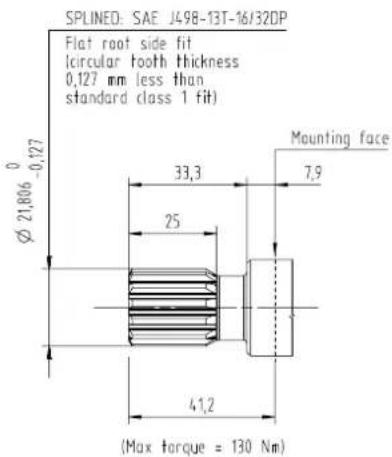
S13
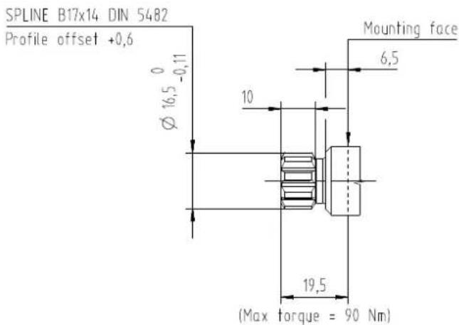
SD1
SD2
Adapter kit
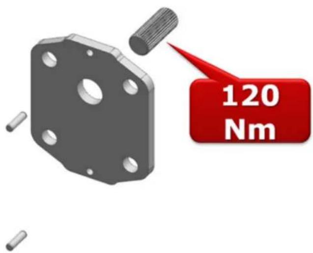
The adapter kit is required to combine two single pumps in one multiple pump. With the special coupling it is possible to sustain up to 120Nm torque transmission, with the following advantages:
High simultaneous working pressure by stages available
High displacements by stages
The intermediate plate has also passed 200 hours salt spray test.
The adapter kit, code 11268956, is composed by:
- Intermediate plate
Dowel
Coupling
Dimensions
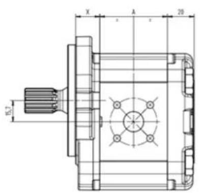
| Frame size 4.0 6.0 8.0 01 | 1014017 | 019022 | 025 | |||||
| Dimension A 50.5 54 58 62 | 687276 | 8286 |
| Mounting flange E10 B10 B20 (B22) SA1 (SA2) SB1 | |||||
| Dimension X 18 20.5 18 18 22 |
Products we offer:
- Cartridge valves
DCV directional control valves
Electric converters
Electric machines
Electric motors
Gearmotors
Gear pumps
Hydraulic integrated circuits (HICs)
Hydrostatic motors - Hydrostatic pumps
Orbital motors
PLUS+1 controllers
PLUS+1* displays
PLUS+1 joysticks and pedals
PLUS+1* operator interfaces
PLUS+1* sensors
PLUS+1* software
PLUS+1 software services, support and training
Position controls and sensors - PVC proportional valves
- Steering components and systems
Telematics
Hydro-Gear
www.hydro-gear.com
Daikin-Sauer-Danfoss
www.daikin-sauer-danfoss.com
Danfoss Power Solutions is a global manufacturer and supplier of high-quality hydraulic and electric components. We specialize in providing state-of-the-art technology and solutions that excel in the harsh operating conditions of the mobile off-highway market as well as the marine sector. Building on our extensive applications expertise, we work closely with you to ensure exceptional performance for a broad range of applications. We help you and other customers around the world speed up system development, reduce costs and bring vehicles and vessels to market faster.
Danfoss Power Solutions – your strongest partner in mobile hydraulics and mobile electrification.
Go to www.danfoss.com for further product information.
We offer you expert worldwide support for ensuring the best possible solutions for outstanding performance. And with an extensive network of Global Service Partners, we also provide you with comprehensive global service for all of our components.
Local address:
Danfoss
Power Solutions (US) Company 2800 East 13th Street
800 East 13th StreetAmes,IA50010,USA
D-24539 Neumunster, Germany
Phone: +49 4321 871 0
Danfoss
Power Solutions ApS
Nordborgvej 81
DK-6430 Nordborg, Denmark
Phone: +45 7488 2222
Danfoss
Power Solutions Trading
(Shanghai) Co., Ltd.
Building #22, No. 1000 Jin Hai Rd
Jin Qiao, Pudong New District
Shanghai, China 201206
Phone: +86 21 2080 6201
Danfoss can opns no responsibility for possible errors in catalogues, brochures and other printed material. Danfoss reserves the right to alter its products without notice. This also applies to products
All trademarks in this material are property of the respective companies. Danfoss and the Danfoss Iogotype are trademarks of Danfoss A/S. All rights reserved.

- Aluminum Group 2 Flex Pump
- Contents
- General Information
- Technical Information
- Product Code
- Mounting flange options
- Shaft options
- Adapter kit
- Dimensions
- Overview
- Pump displacements
- Caution
- Pump model code - Modules
- A Family
- B Displacement
- C Rotation
- D Mounting flange
- E Drive Shaft
- F Inlet size; G Outlet size
- I Rear cover
- L Shaft seal
- M Sealing
- N Screws
- O Valve settings
- P Marking type
- Q marking position
- R Special features
- Products we offer:
- Hydro-Gear
- Daikin-Sauer-Danfoss
- Go to www.danfoss.com for further product information.
- Danfoss
Brand : DANFOSS
Model : GearMe
Category : Pump